

Page 1

EPSON
Programming Guide
For
6 Color
EPSON Stylus Ink Jet Printer
Stylus Photo 870
(Level I)
EPSON Imaging Technology Center Released: 10/6/00
Revision: 1
Page 2

All Rights Reserved. This publication may only be used for the purposes of research and
development of products and services enhancing, enabling, or facilitating existing and future
products and services bearing the EPSON trademark, and for providing support to those engaging
or intending to engage in such activities. All other uses are unauthorized. No part of this
publication may be reproduced, stored in any retrieval system, or transmitted in any form or by
any means without the prior written permission of Seiko Epson Corporation for any purpose other
than the authorized users. No patent liability is assumed with respect to the use of the
information contained within. While every precaution has been taken in the preparation of this
information, Seiko Epson Corporation and its affiliates assume no responsibility for errors or
omissions. Neither is any liability assumed for damages resulting from the use of the information
presented within.
EPSON and EPSON ESC/P are registered trademarks and EPSON ESC/P 2 is a trademark of SEIKO
EPSON Corporation.
Copyright
2000 by SEIKO EPSON Corporation, Nagano, Japan
EPSON Imaging Technology Center Page: 2
Revision: 1 10/6/00
Page 3

TABLE OF CONTENTS:
CHAPTER 1 : INTRODUCTION................................
1.1 EPSON STYLUS PHOTO 870
...............................................................
CHAPTER 2 PAPER - TYPES, SIZES AND ORIENTATION MODE ................
2.1 EPSON PAPER TYPES AND SIZES FOR THE STYLUS PHOTO 870
2.2 EPSON PAPER TYPES AND ORIENTATION FOR THE STYLUS PHOTO 870
CHAPTER 3 RECOMMENDATIONS ................................
3.1 PRINTING MODE SETTI NGS OF THE EPSON STYLUS COLOR 460
3.2 COLOR INK MODE SETTING RECOMMENDATIONS FOR THE STYLUS COLOR 870
3.3 BLACK INK MODE SETTING RECOMMENDATIONS FOR THE STYLUS COLOR 870
CHAPTER 4 PRINTABLE AREAS ................................
4.1 PRINTABLE AREA - STYLUS PHOTO 870
4.2 PRINTABLE AREAS FOR STANDARD SIZE PAPERS
...............................................
................................................................
..............................
.........................................
................................................................
............................
............................................
................................................................
..................................................
.........................................
............... 7
..............................
................ 9
................................
......................
......... 12
..................
.............
.............
............ 14
........................
11
12
12
13
14
15
7
9
4.3 PRINTABLE AREAS FOR USER DEFINED PAPER SIZES
CHAPTER 5 COMMAND SEQUENCE FLOW................................
5.1 RASTER GRAPHICS MODES
5.2 NON-COMPRESSED MODE & RLL COMPRESSION MODE COMMAND TRANSFER SEQUENCES..17
5.3 TIFF COMPRESSION MODE COMMAND TRANSFER SEQUENCES
5.4 ROLL PAPER MODE COMMAND TRANSFER SEQUENCES
.............................................................
CHAPTER 6 INIDIVIDUAL COMMAND SPECIFICATIONS.....................
6.1 LINE FEED “LF”
6.2 FORM FEED “FF”
6.3 CARRIAGE RETURN “CR”
6.4 CARRIAGE RETURN “ESC EM N”
6.5 SET ABSOLUTE HORIZONTAL PRINT POSITION “ESC $ NL NH”
6.6 SET ABSOLUTE HORIZONTAL PRINT POSITION “ESC ( $ NL NH M1 M2 M3 M4”
........................................................................
.......................................................................
...............................................................
.........................................................
......................................
..................................
................................................................
............................
...................................
..................... 21
..........................................
.............................
...............
.. 16
....
15
16
19
20
21
22
23
24
25
26
6.7 SET PAGE LENGTH IN DEFINED UNIT “ESC (C NL NH ML MH”
..............................
EPSON Imaging Technology Center Page: 3
Revision: 1 10/6/00
27
Page 4

6.8 SET PAGE LENGTH IN DEFINED UNIT(EXTENDED) “ESC (C NL NH M1 M2 M3 M4”
............
28
6.9 SELECT GRAPHICS MODE “ESC (G NL NH M”
6.10 SET UNIT “ESC (U NL NH M”
6.11 SET UNIT(EXTENDED) “ESC (U NL NH P V H ML MH”
6.12 SET ABSOLUTE VERTICAL PRINT POSITION “ESC (V NL NH ML MH”
6.13 SET ABSOLUTE VERTICAL PRINT POSITION(EXTENDED) “ESC (V NL NH M1 M2 M3 M4”
6.14 SET PAGE FORMAT “ESC (C NL NH TL TH BL BH”
6.15 SET PAGE FORMAT(EXT ENDED) “ESC (C NL NH T1 T2 T3 T4 B1 B2 B3 B4”
6.16 SELECT MICROWEAVE PRINT MODE “ESC (I”
6.17 SELECT DOT SIZE “ESC (E NL NH M D”
6.18 SELECT COLOR “ESC (R NL NH M N”
6.19 SET RELATIVE VERTICAL PRINT POSITION “ESC (V NL NH ML MH”
6.20 SET RELATIVE VERTICAL PRINT POSITION “ESC (V NL NH M1 M2 M3 M4”
6.21 PRINT RASTER GRAPHICS “ESC . C V H M NL NH D1...DK (C=0,1)”
...........................................................
....................................................
.............................................
.....................................
.......................
.........................................
...................
............................................
..................................................
........................
..................
..........................
.....
29
30
31
32
33
34
35
37
38
39
40
41
42
6.22 ENTER TIFF COMPRESSED MODE “ESC . 2 V H 1 0 0”
6.23 SET PAPER DIMENSION “ESC (S NL NH W1 W2 W3 W4 L1 L2 L3 L4”
6.24 SET RESOLUTION OF RASTER IMAGE “ESC (D NL NH RL RH V H”
6.25 TRANSFER RASTER IMAGE “ESC I R C B NL NH ML MH D1......DK”
6.26 INITIALIZE PRINTER “ESC @”
6.27 TURN UNIDIRECTIONAL MODE ON/OFF “ESC U N”
6.28 SET RELATIVE HORIZONTAL PRINT POSITION “ESC \ NL NH”
6.29 SET RELATIVE HORIZONTAL PRINT POSITION “ESC (/ NL NH N1 N2 M1 M2”
6.30 SELECT PRINTING COLOR “ESC R N”
6.31 EXTENDED RASTER GRAPHICS SPECIFIC COMMANDS-BINARAY MODE COMMANDS FOR“ESC
.......................................................................................
.2”
6.32 SELECT PRINTING COLOR “<COLR>”
6.33 CARRIAGE RETU RN TO LEFT-MOST P RINT POSIT ION “<CR >”
..........................................................
....................................................
...................................................
......................................
........................
........................
.........................
.......................................
..............................
.................
.............................
45
47
48
50
51
52
53
54
55
56
58
59
6.34 EXIT TIFF COMPRESSED MODE “<EXIT>”
6.35 SET RELATIVE HORIZONTAL POSITION “<MOVX >”
...............................................
......................................
EPSON Imaging Technology Center Page: 4
Revision: 1 10/6/00
60
61
Page 5

6.36 SET <MOVX> UNIT TO 8 DOTS <MOVXB YTE >”
..........................................
62
6.37 SET <MOVX> UNIT TO 1 DOT <MOVXDOT>”
6.38 SET RELATIVE VERTICAL POSITION < MOVY >”
6.39 TRANSFER RASTER GRAPHICS DATA < XFER >”
6.40 EPSON PACKET MODE EXIT COMMAND (SPECIAL COMMAND)”0 0 0 ESC 1 @EJL 20H 1284.4 0AH
@EJL 20H 20H 20H 20H 20H 0AH”
6.41 ENTER REMOTE MODE ESC "(R" 08H 00H 00H "REMOTE1
6.42 SELECT PAPER FEED SEQUENCE "SN" 03H 00H 00H M1 M2
6.43 SELECT PAPER FEED SEQUENCE "EX" 03H 00H 00H M1 M2
6.43 SET ROLL PAPER MODE “EX" 06H 00H 00H 00H 00H 00H 05H M1
6.44 TERMINATE REMOTE MODE ESC 00H 00H 00H
............................................................
.............................................
..........................................
..........................................
.................................
................................
................................
............................
...........................................
63
64
65
66
67
68
72
73
74
EPSON Imaging Technology Center Page: 5
Revision: 1 10/6/00
Page 6

LIST OF TABLES:
Table 1 EPSON Stylus Photo 870 Printer Feature Summary...............................................................8
Table 2 The EPSON Stylus Photo 870 Paper Types and Sizes...........................................................9
Table 3 Paper Types and Orientation ..................................................................................................11
Table 4 Recommended Print Mode settings.......................................................................................12
Table 5 Color ink printing recommendations.....................................................................................12
Table 6 Black ink printing recommendations.....................................................................................13
Table 7 Printable area diagram.............................................................................................................14
Table 8 Standard Printable area values for A, B, D and E according to the printable area diagram.
15
Table 9 Maximum Printing area values for A, B, D and E for user-defined paper sizes.................15
Table 10
Stylus Photo 870...............................................................................................................................17
Table 11
Table 12
Table 13
command...........................................................................................................................................69
Table 14
command...........................................................................................................................................70
Table 15
command...........................................................................................................................................70
Command Setting Procedure of non-compressed and RLL compression mode for
Command sequences for TIFF Compression Mode.........................................................19
Command sequences for Roll Paper Mode.......................................................................20
Values for 2nd paramter when 1st parameter is 00H (Paper feed mode) in the SN
Values for 2nd parameter when 1st parameter is 01H (Paper gap mode) in the SN
Values for 2nd parameter when 1st parameter is 02H (Feed speed mode) in the SN
EPSON Imaging Technology Center Page: 6
Revision: 1 10/6/00
Page 7

This Programming Guide is intended for use in conjunction with the EPSON Standard
ESC/P Reference Manual (December 1997)
CHAPTER 1 : INTRODUCTION
This section of the Programming Guide will provide a technical overview of EPSON’s Stylus
Photo 870 inkjet printer to facilitate driver development.
1.1 EPSON Stylus Photo 870
The Stylus Photo 870 is a six-color inkjet printer from EPSON. The Stylus Photo 870 is
targeted for home photography uses. Printouts are intended to last as long as traditional color
photo lab prints, using 1440 x 720 dpi. This printer allows continuous edge-to-edge snapshots
with the EPSON Digital PhotoLab Starter Kit. The starter kit includes a roll paper holder,
EPSON Premium Glossy Photo Roll Paper and helpful photo software like EPSON Software
Film Factory and Adobe PhotoDeluxe. The user will be capable of printing snapshots,
personal photo greeting cards and bigger-than-life panoramics.
Excluding the Japanese market, this printer is sold world wide as the Stylus Photo 870.
The Stylus Photo 870 uses the Micro Piezo print head and two-cartridges. It uses one black ink
cartridge and one multicolor cartridge that contains five inks. The five inks in the single
multicolor cartridge are Yellow, Cyan, Light-Cyan, Magenta and Light-Magenta. All of the color
inks have the same ink formulation.
The EPSON Stylus Photo 870 printer incorporates the following features:
Six individual ink colors
•
Built in Automatic Sheet Feeder (ASF)
•
Built-in 8-bit bidirectional parallel interface (IEEE-1284)
•
Print densities up to 1440(H) x 720(V)
•
Wide range of paper types
•
With the Stylus Photo 870’s bi-directional interfaces and EPSON’s Remote Mode bi-directional
printer control language, the host computer can obtain key printer status information.
This document doesn’t contain information for an individual ISV’s specific driver development,
but does contain the new ESC/P 2 commands associated with the Stylus Photo 870’s ability to
reproduce subtle tone variations. For example, commands such as: Select dot Size “ESC ( e”,
Select Ink Color “ESC ( r”, and a few recently enhanced ESC/P 2 commands are included in this
section of the Programming Guide.
EPSON Imaging Technology Center Page: 7
Revision: 1 10/6/00
Page 8
Table 1 EPSON Stylus Photo 870 Printer Feature Summary
EPSON Stylus Photo 870
48 black nozzles Print Head
240 color nozzles, 48 nozzles x 5 (CcMmY).
Interface (s) Parallel, and Serial
Printer Language ESC/P Raster & Re mot e Mode
Max Resolution (dpi) 1440(h) x 720(v)
Selectable dot size Yes
Ink Type ***CcMmYK
Ink Droplet Size 4 picoliters
*** - CcMmYK refers to: Cyan, Light Cyan, Magenta, Light Magenta, Yellow and Black
EPSON Imaging Technology Center Page: 8
Revision: 1 10/6/00
Page 9
CHAPTER 2 PAPER - TYPES, SIZES AND ORIENTATION MODE
2.1 EPSON Paper Types and Sizes for the Stylus Photo 870
EPSON Stylus Photo 870 printer will print on paper in the following sizes:
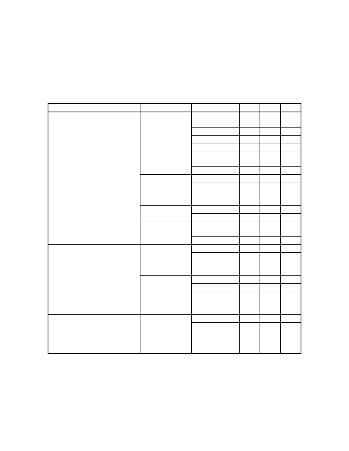
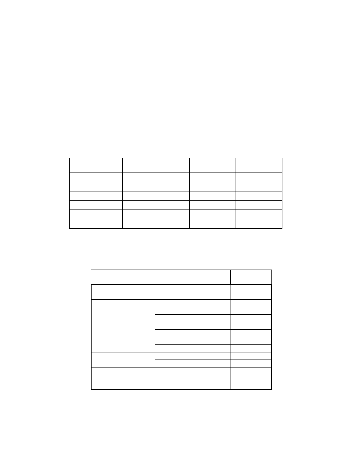
Table 2 The EPSON Stylus Photo 870 Paper Types and Sizes
Paper Type Size US EU JPN
Plain paper Cut sheets Legal Yes Yes Yes
Letter Yes Yes Yes
Executive Yes No No
Half-Letter Yes No No
A4 Yes Yes Yes
A5 No Yes No
B5 No No Yes
User-defined Yes Yes Yes
Envelopes #10 Yes Yes No
C6 Yes Yes No
DL Yes Yes No
132x220 Yes Yes No
Postcards Postcard No No Yes
(card) Return Postcard No No Yes
Index cards A6 No Yes No
(card) 5in. x 8in. Yes Yes No
8in. x 10in. Yes Yes No
Photo Quality Ink Jet Paper Cut sheets Legal Yes No No
Letter Yes No No
A4 No Yes Yes
Postcard (card) Postcard No No Yes
Index card A6 No Yes No
(card) 5in. x 8in. Yes Yes No
8in. x 10in. Yes Yes No
Matte Paper - Heavyweight Cut sheets Letter Yes No No
A4 No Yes No
360 dpi Ink Jet Paper Cut sheets Letter Yes No No
A4 No Yes No
Index card (card) A6 Yes Yes No
Postcard (card) Postcard
(Address Side)
No No No
EPSON Imaging Technology Center Page: 9
Revision: 1 10/6/00
Page 10
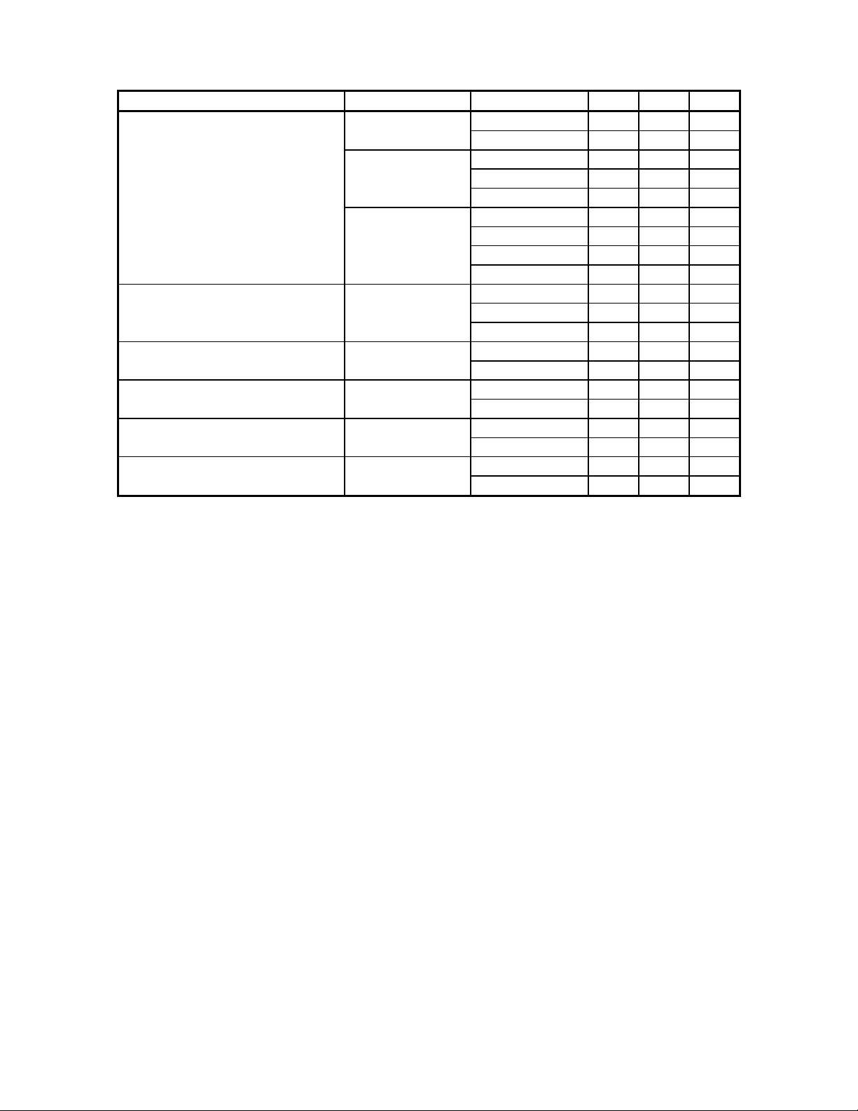
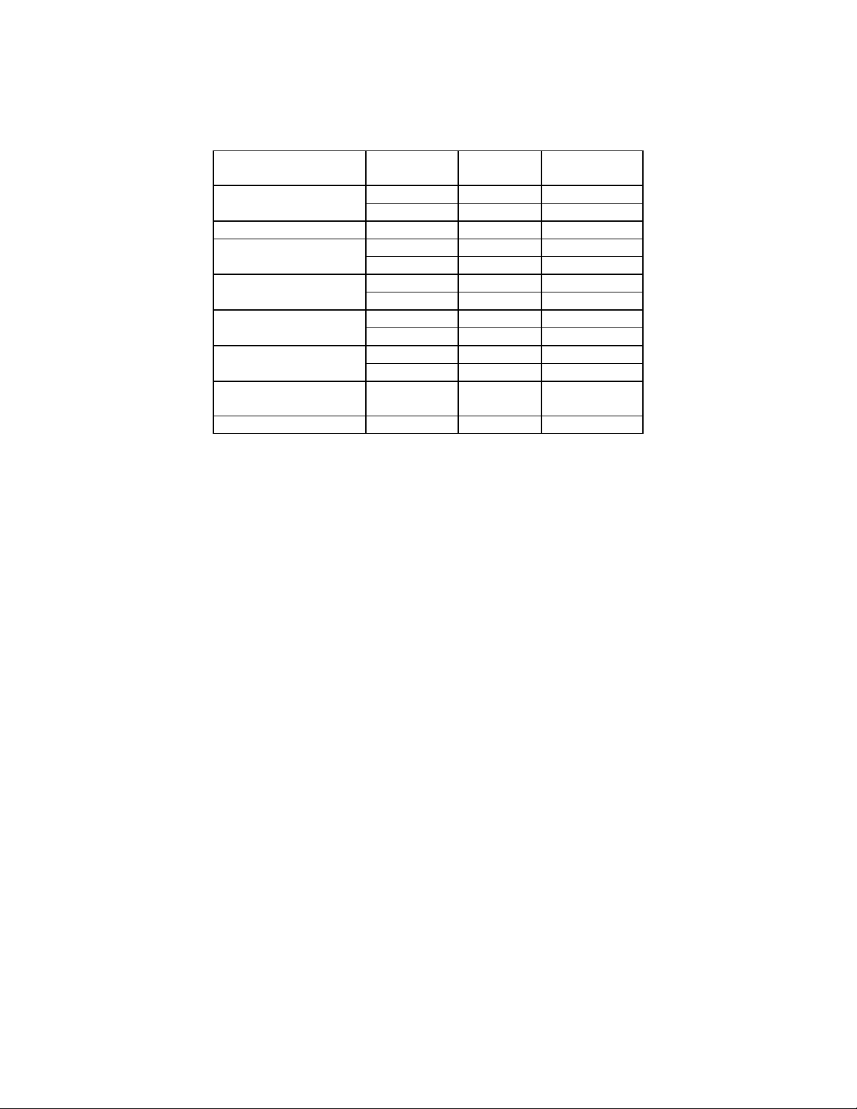
Paper Type Size US EU JPN
Photo Paper Cut sheets Letter Yes No No
A4 No Yes Yes
Photo Paper (card) 113.6x175.4mm Yes Yes Yes
Photo Paper 100x150 mm No Yes No
Photo Paper 200x300 mm No Yes No
Postcard (card) Postcard No No Yes
Roll Paper W A4 Yes Yes Yes
W 100mm Yes Yes Yes
W 89mm Yes Yes Yes
Photo Quality Glossy Film Cut sheets Letter Yes No No
A4 No Yes Yes
A6 Yes Yes Yes
Ink Jet Transparencies Cut sheets Letter Yes No No
A4 No Yes Yes
Photo Quality Adhesive sheet Cut sheets Letter Yes No No
A4 No Yes Yes
Iron-on Cool Peel Transfer Paper Cut sheets Letter Yes No No
A4 No Yes Yes
Photo Stickers 16 cut up A6 Yes Yes No
Hagaki No No Yes
EPSON Imaging Technology Center Page: 10
Revision: 1 10/6/00
Page 11
2.2 EPSON Paper Types and Orientation for the Stylus Photo 870
EPSON Stylus Photo 870 printer will print with portrait or landscape orientation as shown:
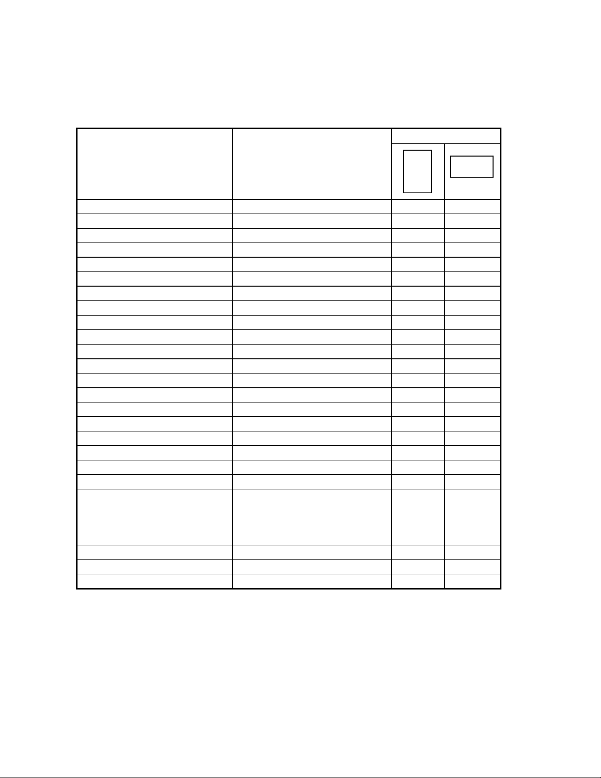
Table 3 Paper Types and Orientation
Orientation
Paper Type Dimensions
W x L
Legal 8.5in. x 14in. Yes No
Letter 8.5in. x 11in. Yes No
A4 210 mm x 297 mm Yes No
A5 148 mm x 210 mm Yes No
A6 105 mm x 148 mm Yes No
Executive 7.25 in. x 10.5 in. Yes No
Half Letter 5.5 in. x 8.5 in. Yes No
B5 182 mm x 257 mm Yes No
Index card 5in. x8in. 5 in. x 8 in. Yes No
Index card 8in. x10in. 8 in. x 10 in. Yes No
Photo Paper 4 in. x 6 in. 113.6 mm x 164.4 mm*1) Yes No
Photo Paper 100x150mm 100 mm x 150 mm Yes No
Photo Paper 200x300mm 216 mm x 338 mm *2) Yes No
Postcard 100 mmx148 mm Yes No
Return postcard 200 mmx148 mm No Yes
#10 Envelope 9.5 in. x 4 .125 in. No Yes
DL Envelope 220 mm x 110 mm No Yes
C6 Envelope 162 mm x 114 mm No Yes
Envelope 132 x 220 220 mm x 132 mm No Yes
Panoramic Photo Paper 210 mm x 594 mm Yes No
User-defined 89 to 241.3 mm
x 89 to 1117.6 mm
(3.5 in. to 9.5 in.
x 3.5 in. to 44 in.)
Roll Paper W A4
Roll Paper W 100 mm
Roll Paper W 89 mm
1) Only “Yes” orientations are allowed for the predetermined paper sizes in the above table.
2) Printing at a rotation of 90° for each of the predeterm ined sizes must be carried out by the
application.
3) *1):Photo Paper 4in.x 6in. :113.6 mm x 164.4 mm is the logical size for the printer driver,
Real paper-size is 113.6 mm x 175.4 mm.
4)
*2):Photo Paper 200 x 300 mm: Top margin non-printable area and Bottom margin
W 210 Yes No
W 100 Yes No
W 89 Yes No
non-printable areas are both 14mm.
↓↓↓↓
Yes No
↓↓↓↓
EPSON Imaging Technology Center Page: 11
Revision: 1 10/6/00
Page 12
CHAPTER 3 RECOMMENDATIONS
The following recommendations are provided for development of printer drivers for the Stylus
Photo 870 printer. The values provided are only starting recommendations. Adjustments to
these values for different halftone modules may improve driver output quality.
3.1 Printing Mode Settings of the EPSON Stylus COLOR 460
The EPSON Stylus Photo 870 supports the following printing modes. More information
regarding commands for these modes of printing can be found in the Individual Command
Specifications portion of this paper.
Table 4 Recommended Print Mode settings
Printing mode
Economy
Normal
Normal
Fine
Photo(720)
Photo(1440)
Print density
(horizontal x vertical)
120(360)dpi x 120dpi
360dpi x 360dpi
360dpi x 360dpi
360dpi x 720dpi
720dpi x 720dpi
1440dpi x 720dpi
Micro Weave 02H value of
SN Command
OFF
OFF
ON
ON
ON
ON
03
02
01
00
00
00
3.2 Color Ink Mode Setting Recommendations for the Stylus COLOR 870
Table 5 Color ink printing recommendations.
Media Print quality Resolution
dpi
Plain paper Normal 360x360 ON
Photo(720) 720x720 ON
360dpi Ink Jet Paper Normal 360x360 OFF
Photo Quality Ink Fine 360x720 ON
Jet Paper Photo(720) 720x720 ON
Matte Paper -
Heavyweight
Photo Paper Fine 360x720 ON
Photo(720) 720x720 ON
RC Paper Fine 360x720 ON
Photo(720) 720x720 ON
Photo Quality Glossy
Film
Ink Jet Transparencies Normal 360x360 OFF
Fine 360x720 ON
Photo(720) 720x720 ON
Photo(720) 720x720 OFF
Bi-directional
printing
EPSON Imaging Technology Center Page: 12
Revision: 1 10/6/00
Page 13
3.3 Black Ink Mode Setting Recommendations for the Stylus COLOR 870
Table 6 Black ink printing recommendations.
Media Print quality Resolution
dpi
Plain paper Normal 360x360 ON
Photo(720) 720x720 ON
360dpi Ink Jet Paper Normal 360x360 OFF
Photo Quality Ink Fine 360x720 ON
Jet Paper Photo(720) 720x720 ON
Matte Paper -
Heavyweight
Photo Paper Fine 360x720 ON
Photo(720) 720x720 ON
RC Paper Fine 360x720 ON
Photo(720) 720x720 ON
Photo Quality Glossy
Film
Ink Jet Transparencies Normal 360x360 OFF
Fine 360x720 ON
Photo(720) 720x720 ON
Photo(1440) 1440x720 OFF
Bi-directional
printing
EPSON Imaging Technology Center Page: 13
Revision: 1 10/6/00
Page 14
D
CHAPTER 4 PRINTABLE AREAS
4.1 Printable Area – Stylus Photo 870
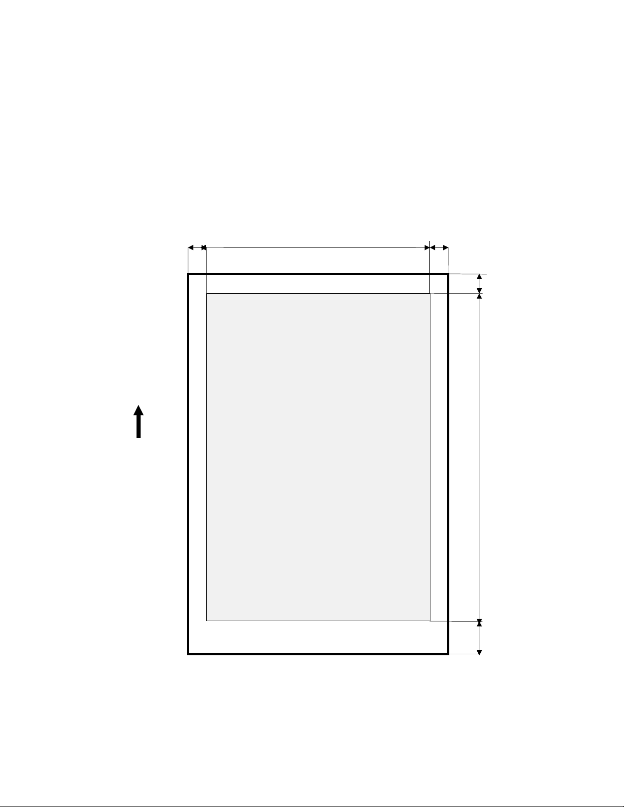
The division of the paper between printing area and non-printing area is controlled by the values
of A, B, C, D, E, G, and H, and by the dot unit (1 dot = 1/360 inch.). When printing near the top
and bottom margins in MicroWeave, printing beyond the regions G and H below which the
nozzles can project is not possibles.
Table 7 Printable area diagram.
Left margin non-printable area
A
Printing area
B
Right margin non-printable area
C
Area nozzle can
project when
processing top
margin
Paper feed direction
P
Top margin non-printable
Printing area
E
area
F
Bottom margin
non-printable area
EPSON Imaging Technology Center Page: 14
Revision: 1 10/6/00
Page 15
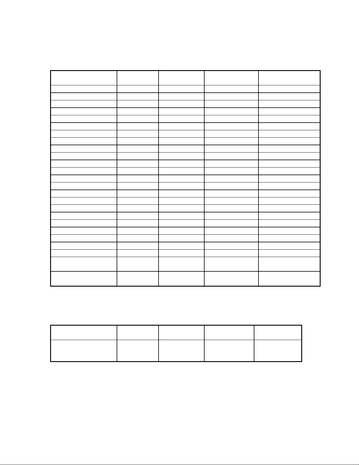
4.2 Printable Areas for Standard Size Papers
Table 8 Standard Printable area values for A, B, D and E according to the printable area diagram.
A/A(Centered) B/B(Centered) D/D(Centered)
/D(Expanded)
Legal 42/42 2976/2976 42/198/42 4800/4644/4956
Letter 42/42 2976/2976 42/198/42 3720/3564/3876
Executive 42/42 2526/2526 42/198/42 3540/3384/3696
Half Letter 42/42 1896/1896 42/198/42 2820/2664/2976
A4 42/42 2892/2892 42/198/42 3969/3813/4125
A5 42/42 2014/2014 42/198/42 2736/2580/2892
A6 42/42 1404/1404 42/198/42 1858/1702/2014
B5 42/42 2496/2496 42/198/42 3403/3247/3559
#10 Envelope 42/(N/A) 2976/(N/A) 42/198/42 1245/1089/1401
DL Envelope 42/(N/A) 2976/(N/A) 42/198/42 1319/1163/1475
C6 Envelope 42/42 2212/2212 42/198/42 1376/1220/1532
Envelope132 x 220 42/42 2976/(NA) 42/198/42 1631/1475/1787
Postcard 42/42 1333/1333 42/198/42 1858/1702/2014
Return postcard 42/42 2751/2751 42/198/42 1858/1702/2014
Index card 5in.x 8in. 42/42 1716/1716 42/198/42 2640/2484/2796
Index card 8in.x 10in. 42/42 2796/2796 42/198/42 3360/3204/3516
Photo Paper 4x6 in. 42/42 1526/1526 42/42/(NA) 2246/2246/(NA)
Panoramic Photo Paper 42/42 2892/2892 42/198/42 8179/8023/8335
Photo Paper 100x150 42/42 1333/1333 42/198/42 1886/1730/2042
Photo Paper 200x300 42/42 2976/2976 42/42/(NA) 4395/4395/(NA)
Roll Paper W A4 42/42 2892/2892 - -
Roll Paper W 100 mm - - - -
Roll Paper W 89 mm - - - -
Roll Paper W 100 mm
No Flame
Roll Paper W 89 mm
No Flame
- - - -
- - - -
E/E(Centered)
E(Expanded)
4.3 Printable Areas for User Defined Paper Sizes
Table 9 Maximum Printing area values for A, B, D and E for user-defined paper sizes.
A/A(Centered) B/B(Centered) D/D(Centered)
/D(expanded)
User-defined
42/42
max. 2976
/ max. 2976
42/198/42
EPSON Imaging Technology Center Page: 15
Revision: 1 10/6/00
E/E(Centered)
E(expanded)
max. 15600
/ max.15444
/ max. 15756
Page 16

CHAPTER 5 COMMAND SEQUENCE FLOW
5.1 Raster Graphics Modes
The following three compression modes are available for raster graphics commands:
1) Non-compressed mode The print data is transferred without compression. This method is
especially effective for printing data with low compression ratio,
such as photographs.
2) RLL compression mode The print data is compressed using RLL (run-length limited) data
compression. This method is especially effective for data with
repeated patterns, such as graphics and illustrations.
3) TIFF compression mode The print data is compressed using TIFF (Tagged Image File
Format) compression. This method is also especially effective for
data with repeated patterns, such as graphs, figures and
illustrations.
In addition, programmers may wish to utilize the roll paper mode.
EPSON Imaging Technology Center Page: 16
Revision: 1 10/6/00
Page 17
5.2 Non-Compressed Mode & RLL Compression Mode Command Transfer Sequences
Command setting procedure for non-compressed mode and RLL compression mode
The basic commands and the sequence in which those commands are to be sent (for noncompressed mode and RLL compression mode) are shown below.
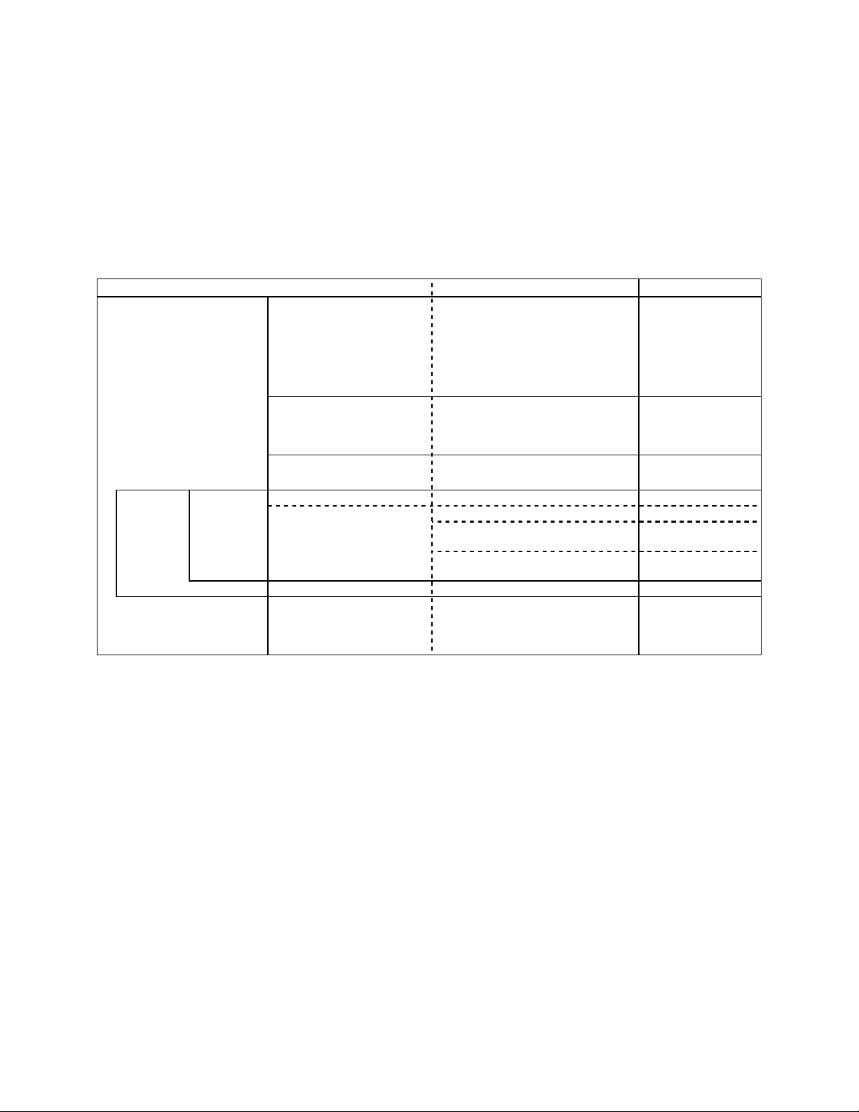
Table 10 Command Setting Procedure of non-co mpressed and RLL compression mode for Stylus
Photo 870
Transfer cycle Details of setting Items set Commands used
By document 1. Initial setting
1.1 Set mechanism sequence
1.2 Initialize printer
1.3 Select graphics mode
1.4 Set unit
ESC (R
SN
ESC 00H 00H 00H
ESC @
ESC ( G
ESC ( U
By page By raster 4. Set vertical position 4.1 Set vertical print position ESC ( V or ESC (v
2. Printing method control 2.1 Turn unidirectional mode on/off
2.2 Select MicroWeave print mode
2.3 Select dot size
3. Set print format
(single sheet)
5. Transfer data 5.1 Select color ESC r or ESC (r
6. Form feed 6.1 Form feed FF
7. Terminate printing 7.1 Initialize printer
3.1 Set page format
3.2 Set paper dimension
5.2 Set horizontal print position ESC \ or ESC(/ or
5.3 Print raster graphics:
repeat above for each color
7.2 Set mechanism sequence
ESC U
ESC ( i
ESC ( e
ESC ( c or ESC( C
ESC (S
ESC $ or ESC ( $
ESC .
ESC @
ESC (R
LD
ESC 00H 00H 00H
EPSON Imaging Technology Center Page: 17
Revision: 1 10/6/00
Page 18

5.3
EPSON Imaging Technology Center Page: 18
Revision: 1 10/6/00
Page 19
TIFF Compression Mode Command Transfer Sequences
The following chart provides basic commands in proper sequence for TIFF compression mode.
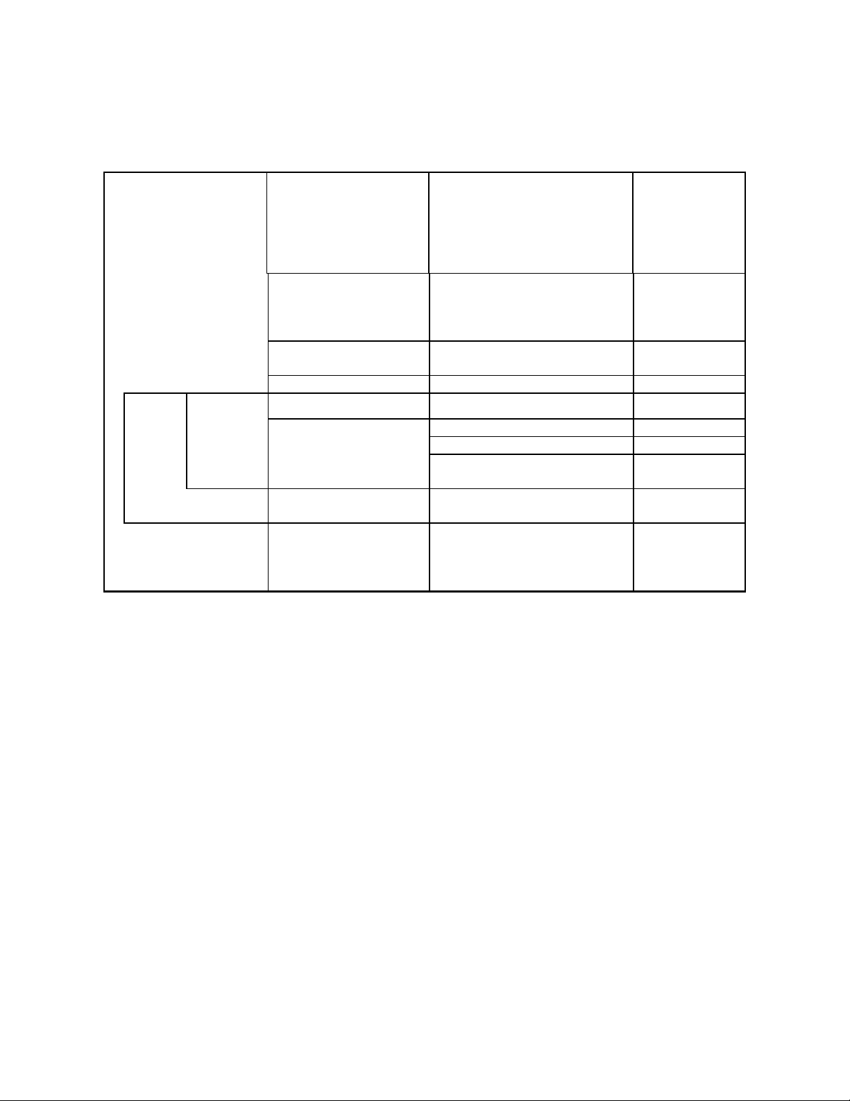
Table 11 Command sequences for TIFF Compression Mode
By document
By page By raster 5. Set vertical position 5.1 Set relative vertical position <MOVY>
1. Initial settings
2. Printing method control 2.1 Turn unidirectional mode on/off
3. Set print format
(single sheet)
4. Enter compression mode 4.1 Enter TIFF compressed mode ESC . 2
1.1 Set mechanism sequence
1.2 Initialize printer
1.3 Select graphics mode
1.4 Set unit
2.2 Select MicroWeave print mode
2.3 Select dot size
3.1 Set page format
3.2 Set Paper dimension
ESC (R
SN
ESC 00H 00H 00H
ESC @
ESC ( G
ESC ( U
ESC U
ESC ( i
ESC ( e
ESC ( c
ESC ( S
6. Transfer data 6.1 Select printing color <COLR>
6.2 Set relative horizontal position <MOVX>
6.3 Transfer raster graphics data
Repeat above for each color
7. Form feed 7.1 Exit TIFF compressed mode
7.2 Form feed
8. Terminate printing
8.1 Initialize printer
8.2 Set mechanism sequence
<XFER>
<EXIT>
FF
ESC @
ESC (R
LD
ESC 00H 00H 00H
EPSON Imaging Technology Center Page: 19
Revision: 1 10/6/00
Page 20
5.4 Roll Paper Mode Command Transfer Sequences
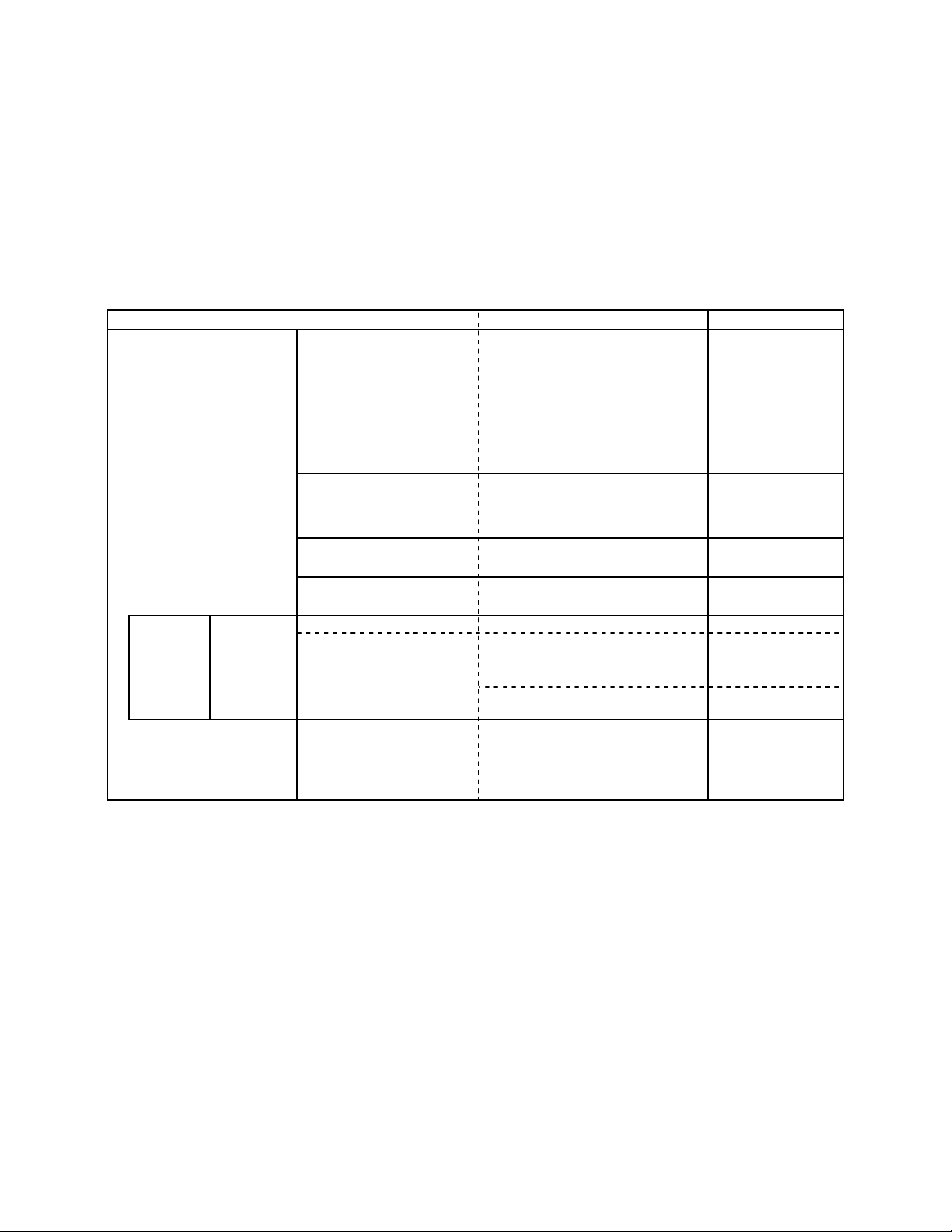
The following chart provides basic commands in proper sequence for the roll paper mode. It
displays the page format setting utilized with the ESC (c command for a top margin 0 setting.
Refer to the explanation of the ESC (c command for further information.
Table 12 Command sequences for Roll Paper Mode
Transfer cycle Details of setting Items set Commands used
By document 1. Initial setting
2. Printing method control 2.1 Turn unidirectional mode on/off
3. Set print format 3.1 Set page format ESC ( C
4. Set top margin 4.1 Set vertical print position ESC ( v
1.1 Set mechanism sequence
Set roll paper mode
1.2 Initialize printer
1.3 Select graphics mode
1.4 Set unit
2.2 Select MicroWeave print mode
2.3 Select dot size
2.4 Set resolution of Raster mode
ESC (R
SN
EX 06H 00H 00H
00H 00H 00H
05H 01H
ESC 00H 00H 00H
ESC @
ESC ( G
ESC ( U
ESC U
ESC ( i
ESC ( e
ESC ( D
ESC ( c
By page By raster 4. Set vertical position 5.1 Set vertical print position ESC (v
7. Terminate printing 7.1 Initialize printer
6.1 Set horizontal print position ESC \ or ESC(/ or
ESC $ or ESC ($
6.2 Print raster graphics:
repeat above for each color
7.2 Set mechanism sequence
7.3 Paper Eject
ESC i
ESC @
ESC (R
LD
ESC 00H 00H 00H
FF
*** Constraint item of the parameter that designates it with ESC(C,ESC(c
ESC (C 02H 00H <n1> <n2>,ESC (c 04H 00H 00H 00H <m1> <m2> : n1=m1,n2=m2
EPSON Imaging Technology Center Page: 20
Revision: 1 10/6/00
Page 21

CHAPTER 6 INIDIVIDUAL COMMAND SPECIFICATIONS
6.1 Line feed “LF”
Format:
ASCII LF
Hex 0A
Decimal 10
Function:
1) Advances the printing position in the Y direction from the current one in the
positive Y direction by an amount equal to the current line separation amount. Sets the printing
position in the X direction to the starting point (the left margin position) on the X axis of the
position management coordinate system.
2) If this commands sets the Y direction printing position into the non-printable
region, then the page is ejected, the position management coordinate system is set to the next
page, and the printing position is set to the origin on this new position management coordinate
system.
Initial State: Related Commands:
Commands related in the direction of applying an effect (Setting)
None
Commands related in the direction of receiving an effect (Setting)
None
Commands related in the direction of applying an effect (Operation)
None
Commands related in the direction of receiving an effect (Operation)
The line advance amount is set by the ESC + commands.
The non-printable region is set by the ESC (c commands.
The line advance amount, the non-printable region, and the left margin position
are reset to their initial states by the ESC @ and ESC (G commands.
EPSON Imaging Technology Center Page: 21
Revision: 1 10/6/00
Page 22

6.2 Form feed “FF”
Format:
ASCII FF
Hex 0C
Decimal 12
Function:
1) The contents of the print buffer are printed, the position management coordinate
system is set to the next page, and the printing position is set to the origin on this new position
management coordinate system.
In addition, if the next page does not exist, the paper is ejected.
2) With single sheet paper, this command is ignored if no paper is input.
Initial State: -
Related Commands:
Commands related in the direction of applying an effect (Setting)
None
Commands related in the direction of receiving an effect (Setting)
None
Commands related in the direction of applying an effect (Operation)
None
Commands related in the direction of receiving an effect (Operation)
The page length is set by the ESC (C commands.
The page length and the left margin position are reset to their initial states by the
ESC @ and ESC (G commands.
EPSON Imaging Technology Center Page: 22
Revision: 1 10/6/00
Page 23

6.3 Carriage return “CR”
Format:
ASCII CR
Hex 0D
Decimal 13
Function:
1) The printing position in the X direction is set to the origin (the left margin) on the
X axis of the position management coordinate system.
Initial State: Related Commands:
Commands related in the direction of applying an effect (Setting)
None
Commands related in the direction of receiving an effect (Setting)
None
Commands related in the direction of applying an effect (Operation)
None
Commands related in the direction of receiving an effect (Operation)
None
EPSON Imaging Technology Center Page: 23
Revision: 1 10/6/00
Page 24

6.4 Carriage return “ESC EM n”
Format:
ASCII ESC EM n
Hex 1B 19 6E
Decimal 27 25 110
Function:
Sets controls for paper loading/ejecting
Range of Values for Parameters:
n=31H, 52H
(="1", "R")
Function:
1) Control of the CSF (cut sheet feeder) is performed as follows, according to the
value of n:
n=31H select bin 1
n=52H eject paper
2) If n has any value other than the above, this command is ignored.
3) ESC EM R is only valid for paper which has been fed from the CSF. For any
other paper, this command is ignored.
4) Bin selection setting is valid from the next time paper is fed.
5) With ESC EM R, the printing position in the X direction is set to the origin on the
X axis.
Initial State: -
Related Commands:
Commands related in the direction of applying an effect (Setting)
None
Commands related in the direction of receiving an effect (Setting)
Returned to initial state by the ESC @ command.
Commands related in the direction of applying an effect (Operation)
None
Commands related in the direction of receiving an effect (Operation)
None
EPSON Imaging Technology Center Page: 24
Revision: 1 10/6/00
Page 25

6.5 Set absolute horizontal print position “ESC $ nL nH”
Format:
ASCII ESC $ nL nH
Hex 1B 24 nL nH
Decimal 27 36 nL nH
Range of Values for Parameters: 0 ≤ nL ≤ 255
0
Function:
1) The printing position in the X direction is set to a position spaced in the positive
direction by (256 x nH + nL) x (absolute horizontal position setting units) inches from the
origin (the left margin position) on the X axis of the position management coordinate
system.
2) If the left margin position + (256 x nH + nL) x (absolute horizontal position
setting units) is past the right margin position, then this command is ignored.
Initial State: -
Related Commands:
Commands related in the direction of applying an effect (Setting)
None
Commands related in the direction of receiving an effect (Setting)
None
Commands related in the direction of applying an effect (Operation)
None
Commands related in the direction of receiving an effect (Operation)
Set the absolute horizontal units with the ESC (U command.
Reset the absolute horizontal position units with the ESC @ and ESC (G
commands.
Return to the initial state using the ESC @ command.
nH ≤ 127
≤
EPSON Imaging Technology Center Page: 25
Revision: 1 10/6/00
Page 26

6.6 Set absolute horizontal print position “ESC ( $ nL nH m1 m2 m3 m4”
Format:
ASCII ESC $ nL nH m1 m2 m3 m4
Hex 1B 24 nL nH m1 m2 m3 m4
Decimal 27 36 nL nH m1 m2 m3 m4
Range of Values for Parameters:
nL=04H, nH=00H
0 <= (m4*1000000H +m3*10000H + m2*100H + m1))×(absolute horizontal position
setting units)inch <= 11904/1440inch
Function:
1) The printing position in the X direction is set to a position spaced in the positive
direction by ((m4×256×256×256 +m3×256×256 + m2×256 + m1) x (absolute horizontal
position setting units) inches from the origin (the left margin position) on the X axis of the
position management coordinate system.
If the left margin position + (m4×256×256×256 +m3×256×256 + m2×256 + m1) x
(absolute horizontal position setting units) is past the right margin position, then this command is
ignored.
This Command is effective only at the time of the graphic mode.
Initial State: -
Related Commands:
Commands related in the direction of applying an effect (Setting)
None
Commands related in the direction of receiving an effect (Setting)
None
Commands related in the direction of applying an effect (Operation)
None
Commands related in the direction of receiving an effect (Operation)
The absolute horizontal position setting units are set by the ESC (U command.
The absolute horizontal position setting units are reset to the initial state by the
ESC @ and ESC (G commands.
The initial state is returned to by the ESC @ command.
EPSON Imaging Technology Center Page: 26
Revision: 1 10/6/00
Page 27

6.7 Set page length in defined unit “ESC (C nL nH mL mH”
Format:
ASCII ESC ( C nL nH mL mH
Hex 1B 28 43 nL nH mL mH
Decimal 27 40 67 nL nH mL mH
Range of Values for Parameters:
nL=02H, nH=00H
0 < ( ( ( mH x 256 ) + mL ) x (page management units) ) ≤ 44 inches
Function:
1) The page length is set to (mH x 256 + mL) x (page management units) inches.
2) If the values of mH and mL are outside the above ranges, this command is
ignored.
3) The page management coordinate system and the position management coordinate
system are set by taking the present Y direction printing position as the origin
upon the Y axis. The origin on the X axis is not changed at this time.
4) The top margin position is set to the origin on the Y axis, and the bottom margin
position is set spaced in the positive direction by the page length from the top
margin position.
Initial State: The page length is set to 22 inches.
Related Commands:
Commands related in the direction of applying an effect (Setting)
The top and bottom margin position settings set by the ESC (c commands are
cleared.
Commands related in the direction of receiving an effect (Setting)
The page length, the page management units, and the top and bottom margin
positions are reset to their initial states by the ESC @ and ESC (G commands.
Commands related in the direction of applying an effect (Operation)
New page processing by the FF command is affected (the amount of movement is
changed).
New lines generated by the LF command which go outside the printable area are
affected.
Processing by the ESC (v command is affected.
Processing by the ESC (V command is affected.
Commands related in the direction of receiving an effect (Operation)
The page management unit is set by the ESC (U command.
EPSON Imaging Technology Center Page: 27
Revision: 1 10/6/00
Page 28

6.8 Set page length in defined unit(extended) “ESC (C nL nH m1 m2 m3 m4”
Format:
ASCII ESC ( C nL nH m1 m2 m3 m4
Hex 1B 28 43 nL nH m1 m2 m3 m4
Decimal 27 40 67 nL nH m1 m2 m3 m4
Range of Values for Parameters:
nL=04H, nH=00H
0<=(m4*1000000H+m3*10000H+m2*100H+m1) *1440/(defined unit) <=1FFFFFFFH
Function:
1) The page length is set to (m4*256*256*256 +m3*256*256 + m2*256 + m1) x
(page management units) inches.
The page management coordinate system and the position management coordinate system
are set by taking the present Y direction printing position as the origin upon the Y axis.
The origin on the X axis is not changed at this time.
The top margin position is set to the origin on the Y axis, and the bottom margin position
is set spaced in the positive direction by the page length from the top margin position.
This Command is effective only at the time of the graphic mode.
Initial State:
The page length is set to 22 inches.
Related Commands:
Commands related in the direction of applying an effect (Setting)
The top and bottom margin position settings set by the ESC (c commands are
cleared.
Commands related in the direction of receiving an effect (Setting)
The page length, the page management units, and the top and bottom margin
positions are reset to their initial states by the ESC @ and ESC (G commands.
Commands related in the direction of applying an effect (Operation)
New page processing by the FF command is affected (the amount of movement is
changed).
New lines generated by the LF command which go outside the printable area are
affected.
Processing by the ESC (v command is affected.
Processing by the ESC (V command is affected.
Commands related in the direction of receiving an effect (Operation)
The page management unit is set by the ESC (U command.
EPSON Imaging Technology Center Page: 28
Revision: 1 10/6/00
Page 29

6.9 Select graphics mode “ESC (G nL nH m”
Format:
ASCII ESC ( G nL nH m
Hex 1B 28 47 nL nH m
Decimal 27 40 71 nL nH m
Range of Values for Parameters:
nL=01H, nH=00H
m=01H or 31H
Function:
1) Shifts to graphics mode.
2) If m has any value other than the above, this command is ignored.
3) Printing of lines up to the present line is started, and the printer waits until the
printing is completed.
4) The various settings are the same as when the power is turned on.
5) The page management coordinate system and the position management coordinate
system are set by taking the printing position in the Y direction at the time of
setting as the origin upon the Y axis.
6) The printing position in the X direction is set to the origin upon the X axis.
7) The microweave print mode selection command is made effective.
Initial State:
Is character mode.
Related Commands:
Commands related in the direction of applying an effect (Setting)
The character mode selection made by the ESC @ command is changed.
Commands related in the direction of receiving an effect (Setting)
The graphics mode is canceled by the ESC @ command.
Commands related in the direction of applying an effect (Operation)
In graphics mode, only the following commands are valid:
LF ESC (C
FF
CR ESC (U
ESC EM ESC (V
ESC. ESC (r
ESC + ESC (v
ESC @ ESC \
ESC (c ESC $
ESC (i ESC r
ESC (K ESC U
ESC ( e ESC ( \
Commands related in the direction of receiving an effect (Operation)
None
EPSON Imaging Technology Center Page: 29
Revision: 1 10/6/00
Page 30

6.10 Set unit “ESC (U nL nH m”
Format:
ASCII ESC ( U nL nH m
Hex 1B 28 55 nL nH m
Decimal 27 40 85 nL nH m
Range of Values for Parameters:
nL=01H, nH=00H
m=05H, 0AH, 14H, 1EH, 28H, 32H, 3CH (units 1/3600 inch)
(=5, 10, 20, 30, 40, 50, 60)
Function:
1) Set the following standard units in units of 1/3600 inch:
Relative horizontal position setting units
Absolute horizontal position setting units
Relative vertical position setting units
Absolute vertical position setting units
Page management units
2) If nL or nH has a value other than the above, then the following (256 x nH + nL)
bytes of data are received, and this command terminates.
3) If m has a value other than the above, this command is ignored.
Initial State:
Page management units: 1/360 inch
Relative horizontal position setting units: 1/180 inch units
Absolute horizontal position setting units: 1/60 inch units
Relative vertical position setting units: 1/360 inch units
Absolute vertical position setting units: 1/360 inch units
Related Commands:
Commands related in the direction of applying an effect (Setting)
None
Commands related in the direction of receiving an effect (Setting)
None
Commands related in the direction of applying an effect (Operation)
The units for the relative horizontal position setting by the ESC \ comma nd are se t.
The units for the absolute horizontal position setting by the ESC $ command ar e set.
The units for the relative vertical position setting by the ESC (v command a re set.
The units for the absolute vertical position setting by the ESC (V command ar e set.
The units for the "unit" unit page length specification by the ESC (C command are set.
The units for the page format specification by the ESC (c command are set.
Commands related in the direction of receiving an effect (Operation)
The initial state is returned to by the ESC @ command.
EPSON Imaging Technology Center Page: 30
Revision: 1 10/6/00
Page 31

6.11 Set unit(extended) “ESC (U nL nH P V H mL mH”
Format:
ASCII ESC ( U nH P V H mL mH
Hex 1B 28 55 nH P V H mL mH
Decimal 27 40 85 nH P V H mL mH
Range of Values for Parameters:
nL=05H, nH=00H
P=( mH*256 + mL ) = 90, 120, 180, 360, 720, 1440
V=( mH*256 + mL ) = 90, 120, 180, 360, 720, 1440
H=( mH*256 + mL ) = 90, 120, 180, 360, 720, 1440
Function:
1) Set the following standard units in units of b/(mH*256+mL) inch:
The H of parameter is horizontal position setting units
The V of parameter is vertical position setting units
The P of parameter is page management units
2) This Command is effective only at the time of the graphic mode.
Initial State:
Page management units: 1/360 inch
Relative horizontal position setting units: 1/180 inch units
Absolute horizontal position setting units: 1/60 inch units
Relative vertical position setting units: 1/360 inch units
Absolute vertical position setting units: 1/360 inch units
Related Commands:
Commands related in the direction of applying an effect (Setting)
None
Commands related in the direction of receiving an effect (Setting)
None
Commands related in the direction of applying an effect (Operation)
The units for the relative horizontal position setting by the ESC \ ,ESC( / command a re
set.
The units for the absolute horizontal position setting by the ESC $,ESC( $ command
are set.
The units for the relative vertical position setting by the ESC (v command a re set.
The units for the absolute vertical position setting by the ESC (V command ar e set.
The units for the "unit" unit page length specification by the ESC (C command are set.
The units for the page format specification by the ESC (c command are set.
The units for the paper dimension specification by the ESC (S command are set.
Commands related in the direction of receiving an effect (Operation)
The initial state is returned to by the ESC @ command.
EPSON Imaging Technology Center Page: 31
Revision: 1 10/6/00
Page 32

6.12 Set absolute vertical print position “ESC (V nL nH mL mH”
Format:
ASCII ESC ( V nL nH mL mH
Hex 1B 28 32 nL nH mL mH
Decimal 27 40 86 nL nH mL mH
Range of Values for Parameters:
nL=02H, nH=00H
(Vertical position set) = (mL + mH x 256) x (units set)
Function:
1) The printing position in the Y direction is set to a position spaced in the positive
direction by (256 x mH + mL) x (the set absolute vertical position unit) inches from the
origin upon the Y axis of the position management coordinate system.
2) If the printing position in the Y direction has been set by this command to a non-
printable region, then the paper is ejected, the position management coordinate system is
set to the next page, and the printing position in the Y direction is reset to the origin upon
the Y axis of the new position management coordinate system.
3) Setting in the negative direction is ignored.
Initial State: Related Commands:
Commands related in the direction of applying an effect (Setting)
None
Commands related in the direction of receiving an effect (Setting)
None
Commands related in the direction of applying an effect (Operation)
None
Commands related in the direction of receiving an effect (Operation)
The absolute vertical position unit are set by the ESC( U commands.
The range of impossible printing are set by the ESC( c, ESC N, ESC O commands.
The relative vertical position setting units, the non-printable region, and the printing
position in the Y direction are reset to their initia l states by the ESC @ and ESC (G
commands.
EPSON Imaging Technology Center Page: 32
Revision: 1 10/6/00
Page 33

6.13 Set absolute vertical print position(extended) “ESC (V nL nH m1 m2 m3 m4”
Format:
ASCII ESC ( V nL nH m1 m2 m3 m4
Hex 1B 28 32 nL nH m1 m2 m3 m4
Decimal 27 40 86 nL nH m1 m2 m3 m4
Range of Values for Parameters:
nL=04H, nH=00H
(Vertical position set) = (mL + mH x 256) x (units set)
0 <= (m4*1000000H+ m3*10000H+m2*100H+m1))×(the set absolute vertical
position unit )inch <= 1FFFFFFFH/1440 inch
Function:
1) The printing position in the Y direction is set to a position spaced in the positive
direction by (m4*256*256*256 +m3*256*256 + m2*256 + m1) x (the set absolute vertical
position unit) inches from the origin upon the Y axis of the position management coordinate
system.
2) If the printing position in the Y direction has been set by this command to a nonprintable region, then the paper is ejected, the position management coordinate system is set to
the next page, and the printing position in the Y direction is reset to the origin upon the Y axis of
the new position management coordinate system.
3) Setting in the negative direction is ignored.
Initial State: Related Commands:
Commands related in the direction of applying an effect (Setting)
None
Commands related in the direction of receiving an effect (Setting)
None
Commands related in the direction of applying an effect (Operation)
None
Commands related in the direction of receiving an effect (Operation)
The absolute vertical position unit are set by the ESC( U commands.
The range of impossible printing are set by the ESC( c, ESC N, ESC O commands.
The relative vertical position setting units, the non-printable region, and the printing
position in the Y direction are reset to their initia l states by the ESC @ and ESC (G
commands.
EPSON Imaging Technology Center Page: 33
Revision: 1 10/6/00
Page 34

6.14 Set page format “ESC (c nL nH tL tH bL bH”
Format:
ASCII ESC ( c nL nH tL tH bL bH
Hex 1B 28 63 nL nH tL tH bL bH
Decimal 27 40 99 nL nH tL tH bL bH
Range of Values for Parameters:
nL=04H, nH =00H
( ( tH x 256 ) + tL ) < ( ( bH x 256 ) + bL )
( ( bH x 256 ) + bL ) x (page management units ) ≤ 44 inches
Function:
1) The position management coordinate system is set by taking as its origin on the Y
axis a position spaced in the positive direction by (256 x tH + tL) x (page
management units) inches from the origin on the Y axis of the page management
coordinate system. Further, the bottom margin is set at a position spaced in the
positive direction by (256 x bH + bL) x (page management units) inches from the
origin on the Y axis of the position management coordinate system.
2) The printing position in the Y direction is shifted to the origin of the position
management coordinate system. At this time, the origin on the X axis is not
changed.
3) If the distance from the origin on the Y axis of the position management
coordinate system to the bottom margin position is greater than the page length,
then this distance from the origin on the Y axis to the bottom margin position is
set as the new page length.
4) If the paper which is inserted is cut sheet paper, then the distance from the top
margin position to the bottom margin position is set as the page length.
Initial State:
The top margin position is set to 0.33 inches .
The bottom margin position is set to the page length.
The page length is set to 22 inches.
Related Commands:
Commands related in the direction of applying an effect (Setting)
The set page length is changed by the ESC (C commands.
Commands related in the direction of receiving an effect (Setting)
The top margin and the bottom margin are set by the ESC commands.
The page length and the bottom margin position are returned to their initial states
by the ESC @ and the ESC (G commands.
Commands related in the direction of applying an effect (Operation)
New page processing by the FF command is affected (the amount of movement is
changed).
New lines generated by the LF command which go outside the printable area are
affected.
Processing by the ESC (v command is affected.
Processing by the ESC (V command is affected.
Commands related in the direction of receiving an effect (Operation)
The page management units are set by the ESC (U command.
EPSON Imaging Technology Center Page: 34
Revision: 1 10/6/00
Page 35

6.15 Set page format(extended) “ESC (c nL nH t1 t2 t3 t4 b1 b2 b3 b4”
Format:
ASCII ESC ( c nL nH t1 t2 t3 b1 b2 b3 b4
Hex 1B 28 63 nL nH t1 t2 t3 b1 b2 b3 b4
Decimal 27 40 99 nL nH t1 t2 t3 b1 b2 b3 b4
Range of Values for Parameters:
nL=08H, nH =00H
0t1,t2,t3,t4,b1,b2,b3,b4255
(t4*1000000H + t3*10000H + t2*100H + t1)<( b4*1000000H + b3*10000H + b2*100H +
b1)<= 1FFFFFFFH/1440 inch
Function:
1) The position management coordinate system is set by taking as its origin on the Y
axis a position spaced in the positive direction by (t4*256*256*256 + t3*256*256
+ t2*256 + t1) x (page management units) inches from the origin on the Y axis of
the page management coordinate system. Further, the bottom margin is set at a
position spaced in the positive direction by (b4*256*256*256 + b3*256*256 +
b2*256 + b1) x (page management units) inches from the origin on the Y axis of
the position management coordinate system.
2) The printing position in the Y direction is shifted to the origin of the position
management coordinate system. At this time, the origin on the X axis is not
changed.
3) If the distance from the origin on the Y axis of the position management
coordinate system to the bottom margin position is greater than the page length,
then this distance from the origin on the Y axis to the bottom margin position is
set as the new page length.
If the paper which is inserted is cut sheet paper, then the distance from the top
margin position to the bottom margin position is set as the page length.
This Command is effective only at the time of the graphic mode.
Initial State:
The top margin position is set to 0.33 inches .
The bottom margin position is set to the page length.
The page length is set to 22 inches.
Related Commands:
Commands related in the direction of applying an effect (Setting)
The set page length is changed by the ESC (C commands.
Commands related in the direction of receiving an effect (Setting)
The top margin and the bottom margin are set by the ESC commands.
The page length and the bottom margin position are returned to their initial states
by the ESC @ and the ESC (G commands.
Commands related in the direction of applying an effect (Operation)
New page processing by the FF command is affected (the amount of movement is
changed).
EPSON Imaging Technology Center Page: 35
Revision: 1 10/6/00
Page 36

New lines generated by the LF command which go outside the printable area are
affected.
Processing by the ESC (v command is affected.
Processing by the ESC (V command is affected.
Commands related in the direction of receiving an effect (Operation)
The page management units are set by the ESC (U command.
EPSON Imaging Technology Center Page: 36
Revision: 1 10/6/00
Page 37

6.16 Select MicroWeave print mode “ESC (i”
Format:
ASCII ESC ( i 01H 00H n
Hex 1B 28 63 01 00 n
Decimal 27 40 105 1 0 n
Range of Values for Parameters:
n=00H, 01H, 30H, 31H
Function:
1) Selects / deselects the MicroWeave mode.
n=0 or 30H: deselects
n=1 or 31H: selects
Initial State:
Non-MicroWeave mode
Related Commands:
Commands related in the direction of applying an effect (Setting)
Changes the non-selected state set by the ESC (G command.
Changes the non-selected state set by the ESC @ command.
Commands related in the direction of receiving an effect (Setting)
The ESC (G command sets the non-selected state.
The ESC @ command sets the non-selected state.
Commands related in the direction of applying an effect (Operation)
None
Commands related in the direction of receiving an effect (Operation)
None
EPSON Imaging Technology Center Page: 37
Revision: 1 10/6/00
Page 38

6.17 Select dot size “ESC (e nL nH m d”
Format:
ASCII ESC ( e nL nH m d
Hex 1B 28 65 nL nH m d
Decimal 27 40 101 nL nH m d
Range of Values for Parameters:
nL=02H, nH=00H
m=00H, d=00H, 01H, 02H, 03H, 04H, 10H
Function:
1) The dot size is set according to the value of d.
2) The parameter has the following meaning:
d=00H: default
for a 360 dpi raster, Normal x3dot
………………for a 720 dpi raster, Normal x1,2 dot
3) The defaults are specific to each model of printer.
4) Dot control is valid irrespective of printing mode and printing density.
5) If the dot size is changed part way through a page, the results are unpredictable.
6) If n has any value other than the above, this command is ignored.
Initial State: Default
Related Commands:
Commands related in the direction of applying an effect (Setting)
None
Commands related in the direction of receiving an effect (Setting)
The default is set by the ESC @ command.
The default is set by the ESC (G command.
Commands related in the direction of applying an effect (Operation)
None
Commands related in the direction of receiving an effect (Operation)
None
EPSON Imaging Technology Center Page: 38
Revision: 1 10/6/00
Page 39

6.18 Select color “ESC (r nL nH m n”
Format:
ASCII ESC ( r nL nH m n
Hex 1B 28 72 nL nH m n
Decimal 27 40 114 nL nH m n
Range of Values for Parameters:
nL=02H, nH=00H
m=00H,01H
n=00H, 01H, 02H, 04H
Function:
1) The print color is selected according to the values of m and n.
m n Print color
00H 00H Black
00H 01H Magenta
00H 02H Cyan
00H 04H Yellow
00H 01H Light Magenta
00H 02H Light Cyan
2) If either m or n has a value other than those above, this command is ignored.
3) This command is only effective in graphics mode.
Initial State: Black is selected.
Related Commands:
Commands related in the direction of applying an effect (Setting)
None
Commands related in the direction of receiving an effect (Setting)
The ESC @ command selects black.
Commands related in the direction of applying an effect (Operation)
None
Commands related in the direction of receiving an effect (Operation)
The ESC (G command sets graphics mode.
EPSON Imaging Technology Center Page: 39
Revision: 1 10/6/00
Page 40

6.19 Set relative vertical print position “ESC (v nL nH mL mH”
Format:
ASCII ESC ( v nL nH mL mH
Hex 1B 28 76 nL nH mL mH
Decimal 27 40 118 nL nH mL mH
Range of Values for Parameters:
nL=02H, nH=00H
(Relative vertical set position) = (mL + mH x 256) x (set units)
Function:
1) The printing position in the Y direction is set to a position spaced in the positive
direction from the present Y printing position in the Y direction by (256 x mH +
mL) x (relative vertical position set unit) inches.
2) If the position set by this command is higher than the top margin position on the
current page, this command is ignored.
3) If the printing position in the Y direction has been set by this command to a nonprintable region, then the position management coordinate system is set to the
next page, and the printing position in the Y direction is reset to the origin upon
the Y axis of the new position management coordinate system.
Initial State: Related Commands:
Commands related in the direction of applying an effect (Setting)
None
Commands related in the direction of receiving an effect (Setting)
None
Commands related in the direction of applying an effect (Operation)
None
Commands related in the direction of receiving an effect (Operation)
The relative vertical position setting units are set by the ESC (U command.
The non-printable region is set by the ESC (c commands.
The relative vertical position setting units, the non-printable region, and the
printing position in the Y direction are reset to their initial states by the ESC @
and ESC (G commands.
EPSON Imaging Technology Center Page: 40
Revision: 1 10/6/00
Page 41

6.20 Set relative vertical print position “ESC (v nL nH m1 m2 m3 m4”
Format:
ASCII ESC ( v nL nH m1 m2 m3 m4
Hex 1B 28 76 nL nH m1 m2 m3 m4
Decimal 27 40 118 nL nH m1 m2 m3 m4
Range of Values for Parameters:
nL=04H, nH=00H
0 <= (m4*1000000H +m3*10000H + m2*10H + m1))×(relative vertical position set
unit)inch <= 1FFFFFFFH/1440 inch
Function:
1) The printing position in the Y direction is set to a position spaced in the positive
direction from the present Y printing position in the Y direction by
(m4*256*256*256 + m3*256*256 + m2*256 + m1) x (relative vertical position
set unit) inches.
Setting in theystem.
2) If the position set by this command is higher than the top margin position on the
current page, this command is ignored.
3) If the printing position in the Y direction has been set by this command to a nonprintable region, then the position management coordinate system is set to the
next page, and the printing position in the Y direction is reset to the origin upon
the Y axis of the new position management coordinate system.
Initial State: Related Commands:
Commands related in the direction of applying an effect (Setting)
None
Commands related in the direction of receiving an effect (Setting)
None
Commands related in the direction of applying an effect (Operation)
None
Commands related in the direction of receiving an effect (Operation)
The relative vertical position setting units are set by the ESC (U command.
The non-printable region is set by the ESC (c commands.
The relative vertical position setting units, the non-printable region, and the
printing position in the Y direction are reset to their initial states by the ESC @
and ESC (G commands.
EPSON Imaging Technology Center Page: 41
Revision: 1 10/6/00
Page 42

6.21 Print raster graphics “ESC . c v h m nL nH d1...dk (c=0,1)”
Format:
ASCII ESC . c v h m nL nH dl…dk
Hex 1B 2E c v h m nL nH dl…dk
Decimal 27 46 c v h m nL nH dl…dk
Range of Values for Parameters:
c=0, 1, 2 (for the cases c=2 as in the separate frame)
v=5, 10, 20, 40 (v/3600 dpi)
h=5, 10, 20 (h/3600 dpi)
0
0
0
m=1, 8, 24, 47,48 (color mode)
1, 8, 24, 72,144 (black mode)
Function:
1) If c has any value other than the above, this command terminates at the instant
that c is processed.
If v has any value other than the above, or if h has any value other than the above,
this command is ignored.
2) The actual image pattern is generated according to a raster method determined by
the following parameters:
Full graphics mode (non-compressed mode)
nL ≤ 255
≤
nH ≤ 127
≤
d ≤ 255
≤
c: printing mode
00H: full graphics mode (non-compressed mode)
01H: run-length encoded compression mode
v: printing density in the vertical direction v/3600 (dpi)
h: printing density in the horizontal direction h/3600 (dpi)
m: number of dots in the vertical direction
nL, nH: number of dots in the horizontal direction 256 x nH + nL (dots)
k: number of items of data = m x int((nH x 256 + nL + 7)/8)
d: data
In full graphics mode, all of the data is transferred in raster format. At this time, for the
last data byte on the right, the portion up until the number of dots in the horizontal
direction is valid.
The total amount of data sent is k = int((256 x nH + nL + 7)/8) x m bytes.
MSB
MSB
MSB
MSB
MSB
MSB
LSB
LSB
LSB
LSB
LSB
LSB
LSB
LSB
LSB
LSB
LSB
LSB
MSB
MSB
MSB
MSB
MSB
MSB
LSB
LSB
LSB
LSB
LSB
LSB
MSB
MSB
MSB
MSB
MSB
MSB
LSB
LSB
LSB
LSB
LSB
LSB
MSB
MSB
MSB
MSB
MSB
MSB
LSB
LSB
LSB
LSB
LSB
LSB
MSBMSB
MSBMSB
MSBMSB
MSBMSB
MSBMSB
MSBMSB
LSB
LSB
LSB
LSB
LSB
LSB
m
256*nH+nL dots
int((256*nH+nL+7)/8) bytes
EPSON Imaging Technology Center Page: 42
Revision: 1 10/6/00
Page 43

Run-length encoding compression mode
In run-length encoding compression mode, the data is transferred in the following
format.
The data to be printed is always transferred in the format (counter) + (data).
If 0 ≤ counter ≤ 127, then the data following the counter is non-compressed data, and
the length of the compressed data is (counter)+1 bytes.
If 128 ≤ counter ≤ 255, then the data following the counter is one byte of
compressed data, and the compressed data is to be considered as being repeated
257-(counter) times.
3) The printing position in the X direction is set to a position spaced in the positive
direction from the present printing position in the X direction by (256 x nH + nL)
x h/3600 inches.
If this command specifies a position in the non-printable area (right margin), the
right margin position is set once again to the X direction print position.
4) If image data upon a non-printable region is designated, this designated data is
ignored.
The combinations of printing density and command parameters which can be set with the raster
graphics of this printer are shown in the following tables:
Case of microweave mode off
0.
Mode Parameter ESC(e *3 Comment
(V x H) c v h m n2
120x120 0/1 30 30 48 00h expanded to 120x360 by the
printer
120x360 0/1 30 10 47/48 00h
120x720 0/1 30 5 47/48 00h
180x180 0/1/2 20 20 1/8/24 00h *1 *2
180x360 0/1 20 10 1/8/24 00h *2
360x360 0/1/2 10 10 1/8/24 00h *1 *2
Case of microweave mode on
1.
Mode Parameter ESC(e *3 Comment
(V x H) c v h m n2
360x360 0/1/2 10 10 1 00h
720x720 0/1/2 5 5 1 00h 2pass printing
*1 When mode is selected as TIFF(c=2), only m=1 is allowed.
*2 The parameter m=1 is recommended.
*3 In the case that the ESC . command is used only MultiShot Dot (ESC ( e 2 0 0 0) is effective.
Initial State:
Character mode
EPSON Imaging Technology Center Page: 43
Revision: 1 10/6/00
Page 44

Related Commands:
Commands related in the direction of applying an effect (Setting)
None
Commands related in the direction of receiving an effect (Setting)
None
Commands related in the direction of applying an effect (Operation)
None
Commands related in the direction of receiving an effect (Operation)
None
EPSON Imaging Technology Center Page: 44
Revision: 1 10/6/00
Page 45

6.22 Enter TIFF compressed mode “ESC . 2 v h 1 0 0”
Format:
ASCII ESC . 2 v h 01H 00H 00H
Hex 1B 2E 32 v h 01 00 00
Decimal 27 46 50 v h 1 0 0
Range of Values for Parameters:
v=5, 10, 20 (v/3600 dpi)
h=5, 10, 20 (h/3600 dpi)
Function:
1) TIFF ver. 4.0 format raster graphics compression mode is set from this command
until the <EXIT> command.
2) This supports the TIFF ver. 4.0 compression method.
3) Each of the parameters has the following meaning:
v: printing density in the vertical direction v/3600 (dpi)
h: printing density in the horizontal direction h/3600 (dpi)
Only the following combinations of printing densities in the vertical direction and
in the horizontal direction are permitted:
Vertical direction (dpi) Horizontal direction (dpi)
180 180
180 360
360 360
720 720
4) The commands which are valid in this mode are the following:
<XFER>: transfer graphics image data
<MOVX>: set horizontal position
<MOVY>: set vertical position
<COLR>: set color
<CR>: set printing position in the X direction to the left margin position
<EXIT>: cancel compressed format mode
<MOVXBYTE>:make the unit of horizontal direction setting into by te units
<MOVXDOT>:make the unit of horizontal direction setting into dot units
5) The units for the <MOVX> and <MOVY> commands are the units set by the
ESC (U command.
6) The printing position in the X direction is set to the origin upon the X axis.
Initial State:
Character mode
Related Commands:
Commands related in the direction of applying an effect (Setting)
The full graphics mode set by the ESC (G command is switched to the run-length
encoding compression mode.
Commands related in the direction of receiving an effect (Setting)
The TIFF ver. 4.0 compression mode is canceled by the EXIT command.
EPSON Imaging Technology Center Page: 45
Revision: 1 10/6/00
Page 46

Commands related in the direction of applying an effect (Operation)
Only the following commands are valid:
XFER CR
MOVX EXIT
MOVY MOVXBYTE
COLR MOVXDOT
Commands related in the direction of receiving an effect (Operation)
The "unit" units are set by the ESC (U command.
EPSON Imaging Technology Center Page: 46
Revision: 1 10/6/00
Page 47

6.23 Set paper dimension “ESC (S nL nH w1 w2 w3 w4 l1 l2 l3 l4”
Format:
ASCII ESC ( S nL nH w1 w2 w3 w4 11 12 13 14
Hex 1B 28 53 nL nH w1 w2 w3 w4 11 12 13 14
Decimal 27 40 83 nL nH w1 w2 w3 w4 11 12 13 14
Range of Values for Parameters:
nL=04H, nH=00H
0 <= ( w4*1000000H + w3*10000H + w2*100H + w1 )*1440/(defined unit) <= 7FFFFFFFH
0 <= ( l4*1000000H + l3*10000H + l2*100H + l1 )*1440/(defined unit) <= 7FFFFFFFH
Function:
1) Set paper length ( from top-edge to bottom-edge ) and paper width ( from leftedge to right-edge ) in the defined unit.
2) This command is used to expand the bottom-margin ( 3mm) of printer.
3) Paper length and width is defined by following formula:
physical paper length = ( l4*1000000H + l3*10000H + l2*100H + l1 ) * ( defined unit )
physical paper width = ( w4*1000000H + w3*10000H + w2*100H + w1 ) * ( defined unit )
4) This command can be used only during graphics mode, entered by sending the
ESC (G command.
5) This command is effective when defined paper length is the same as physical
paper length measured by the printer.
6) The image from a remainder page manager is deleted from the location of a form
piece, in the case that it is shorter than it is long the form that was designated with
this command although it is long a physics form.
7) The paper width is ignored in this printer.
Initial State: Related Commands:
Commands related in the direction of applying an effect (Setting)
None
Commands related in the direction of receiving an effect (Setting)
The page control setting unit is set by the ESC (U command.
Commands related in the direction of applying an effect (Operation)
None
Commands related in the direction of receiving an effect (Operation)
The initial state is returned to by the ESC @ command.
The initial state is returned to by the ESC(G command.
EPSON Imaging Technology Center Page: 47
Revision: 1 10/6/00
Page 48

6.24 Set resolution of Raster image “ESC (D nL nH rL rH v h”
Format:
ASCII ESC ( D nL nH rL rH v h
Hex 1B 28 44 nL nH rL rH v h
Decimal 27 40 68 nL nH rL rH v h
Range of Values for Parameters:
nL=04H, nH=00H
0 <= v <= 127
0 <= h <=127
Function:
1) Set resolution of raster image ( ESC i ).
Vertical resolution : v / ( rH*256 + rL ) inch
Horizontal resolution : h / ( rH*256 + rL ) inch
2) Available resolution is
1/120, 1/180, 1/360, 1/720, 1/1440 inch
3) Following parameters are supported.
4)
Case of microweave mode off
0.
Mode ESC ( D ESC i Comment
(V x H) v / r h / r mH*256+
mL
120x120 12/1440 12/1440 48 expanded to 120x360 by the printer
120x360 12/1440 4/1440 47/48
180x180 8/1440 8/1440 1/8/24 *1
180x360 8/1440 4/1440 1/8/24 *1
360x360 4/1440 4/1440 1/8/24 *1
Case of microweave mode on
1.
Mode ESC ( D ESC i Comment
(V x H) v / r h / r mH*256+
mL
360x360 4/1440 4/1440 1
*1 The parameter (mH*256+mL)=1 is recommended.
Initial State: Related Commands:
Commands related in the direction of applying an effect (Setting)
The Resolution set of Raster image exert the influence on the processing by the
ESC i command .
EPSON Imaging Technology Center Page: 48
Revision: 1 10/6/00
Page 49

Commands related in the direction of receiving an effect (Setting)
The Resolution setting of Raster image is returned to this initial states by the ESC
@ and the ESC (G commands.
Commands related in the direction of applying an effect (Operation)
None
Commands related in the direction of receiving an effect (Operation)
None
EPSON Imaging Technology Center Page: 49
Revision: 1 10/6/00
Page 50

6.25 Transfer Raster image “ESC i r c b nL nH mL mH d1......dk”
Format:
ASCII ESC I r c b nL nH mL mH d1 d2…dk
Hex 1B 69 r c b nL nH mL mH d1 d2…dk
Decimal 27 105 r c b nL nH mL mH d1 d2…dk
Range of Values for Parameters:
r = 00H, 01H, 02H, 04H
c = 00H, 01H
b = 01H, 02H
0000H <= ( nH*256 + nL ) <= 7FFFH
0001H <= ( mH*256 + mL ) <= 7FFFH
Function:
1) Prints dot graphics in raster format.
2) Parameters are used as described below:
r : color of image ( 00H:black, 01H:magenta, 02H:cyan, 04H:yellow )
c : compress method ( 00H:noncompressed, 01H:Run Length
Encoding )
b : bit length of each pixel ( 01H:1bit/pixel (for Micro, Normalx1,
Normalx2, Normalx4 dot)
nL, nH: Horizontal byte count, according to the following formula:
nH = INT( horizontal byte count / 256 )
= INT( ( ( horizontal dot count ) * ( bit lenght of each pixel ) + 7 ) /
8 ) /256
nL = MOD(horizontal byte count / 256 )
= MOD( ( ( horizontal dot count ) * ( bit lenght of each pixel ) + 7
) / 8 ) /256
mL, mH: Vertical dot count ( rows of dot graphics ), according to the
following formula:
mH = INT(vertical dot count / 256 )
mL = MOD(vertical dot count / 256 )
k : Total numbers of data bytes, accoriding to the following formula:
k = ( nH*256 + nL ) * ( mH*256 + mL )
Initial State: -
EPSON Imaging Technology Center Page: 50
Revision: 1 10/6/00
Page 51

6.26 Initialize printer “ESC @”
Format:
ASCII ESC @
Hex 1B 40
Decimal 27 64
Range of Values for Parameters: Function:
1) The various settings are returned to their initial values.
2) The page management coordinate system and the position management coordinate
system are set by taking the origin upon the Y axis as the present printing position
on the Y axis.
3) The present printing position on the X axis is set to the origin upon the X axis.
4) The text mode is selected.
Initial State: Related Commands:
Commands related in the direction of applying an effect (Setting)
The settings for all commands are returned to their initial states.
Commands related in the direction of receiving an effect (Setting)
None
Commands related in the direction of applying an effect (Operation)
None
Commands related in the direction of receiving an effect (Operation)
None
EPSON Imaging Technology Center Page: 51
Revision: 1 10/6/00
Page 52

6.27 Turn unidirectional mode on/off “ESC U n”
Format:
ASCII ESC U n
Hex 1B 55 n
Decimal 27 85 n
Range of Values for Parameters:
n=00H, 01H, 02H, 30H, 31H, 32H
Function:
1) The printing direction is selected according to the value of n in the following manner:
n=00H or 30H: selects bi-directional printing
n=01H or 31H: selects unidirectional printing
n=02H or 32H: selects automatic printing direction control
2) If n has any value other than the above, this command is ignored.
Initial State:
Bi-directional printing
Related Commands:
Commands related in the direction of applying an effect (Setting)
Initialization carried out by the ESC @ command is cancelled.
Commands related in the direction of receiving an effect (Setting)
Returned to its initial state by the ESC @ command.
Commands related in the direction of applying an effect (Operation)
None
Commands related in the direction of receiving an effect (Operation)
None
EPSON Imaging Technology Center Page: 52
Revision: 1 10/6/00
Page 53

6.28 Set relative horizontal print position “ESC \ nL nH”
Format:
ASCII ESC \ nL nH
Hex 1B 5C nL nH
Decimal 27 92 nL nH
Range of Values for Parameters:
(nL + 256 x nH) x (set units) inches
Function:
1) If bit 6 of nH is 1, this is taken as meaning that a negative value has been set, and
it is considered that the MSB of nH is 1. Negative values are expressed in two's
complement.
2) The printing position in the X direction is set to a position spaced in the positive
direction from the present printing position in the X direction by (256 x nH + nL)
x (the set relative horizontal position setting unit).
Set the defined unit with the ESC (U command.
The default defined unit for this command is 1/180inch.
3) If the position setting due to this command is within the non-printable region, it is
ignored. However, it is possible to shift to a position on the right margin position.
Initial State: Related Commands:
Commands related in the direction of applying an effect (Setting)
None
Commands related in the direction of receiving an effect (Setting)
None
Commands related in the direction of applying an effect (Operation)
None
Commands related in the direction of receiving an effect (Operation)
The relative horizontal position setting units are set by the ESC (U command.
The relative horizontal position setting units are reset to the initial state by the
ESC @ and the ESC (G command.
EPSON Imaging Technology Center Page: 53
Revision: 1 10/6/00
Page 54

6.29 Set relative horizontal print position “ESC (/ nL nH n1 n2 m1 m2”
Format:
ASCII ESC ( / nL nH n1 n2 m1 m2
Hex 1B 28 2F nL nH n1 n2 m1 m2
Decimal 27 40 47 nL nH n1 n2 m1 m2
Range of Values for Parameters:
nL=04H, nH=00H
0 <= (m4*1000000H +m3*10000H + m2*100 + m1))×(relative horizontal print position
set unit)inch <= 11904/1440inch or
If bit 7 of m4 is 1,this is taken to mean that a negative value has been set.
Function:
1) If bit 7 of m4 is 1, this is taken as meaning that a negative value has been set.
Negative values are expressed in two's complement.
2) The printing position in the X direction is set to a position spaced in the positive
direction from the present printing position in the X direction by (m4×256×256×
256 +m3×256×256 + m2×256 + m1) x (the set relative horizontal position setting
unit).
Set the defined unit with the ESC (U command.
The default defined unit for this command is 1/60inch.
If the position setting due to this command is within the non-printable region, it is
ignored. However, it is possible to shift to a position on the right margin position.
This command is only effective in graphics mode.
Initial State: Related Commands:
Commands related in the direction of applying an effect (Setting)
None
Commands related in the direction of receiving an effect (Setting)
None
Commands related in the direction of applying an effect (Operation)
None
Commands related in the direction of receiving an effect (Operation)
None
EPSON Imaging Technology Center Page: 54
Revision: 1 10/6/00
Page 55

6.30 Select printing color “ESC r n”
Format:
ASCII ESC r n
Hex 1B 72 n
Decimal 27 114 n
Range of Values for Parameters:
00H
Function:
1) The printing color is selected according to the value of n, as follows:
2) If n has a value other than the above, this command is ignored.
Initial State:
Black selected.
Related Commands:
Commands related in the direction of applying an effect (Setting)
None
Commands related in the direction of receiving an effect (Setting)
The ESC @ command selects black.
Commands related in the direction of applying an effect (Operation)
None
Commands related in the direction of receiving an effect (Operation)
None
n ≤ 06H
≤
if n=0: black
if n=1: magenta
if n=2: cyan
if n=4: yellow
EPSON Imaging Technology Center Page: 55
Revision: 1 10/6/00
Page 56

6.31 Extended Raster Graphics Specific Commands-Binaray Mode Commands for“ESC
.2”
Format:
<xxxxxxxx>B (Command byte)
Range of Values for Parameters: Function:
1) The internal commands fall into two groups.
First group: Group of commands in which the parameter is embedded in the
command byte:
XFER
MOVX
MOVY
COLR
Second group: Group of commands in which the parameters are not embedded in
the command byte:
CLR
CR
EXIT
MOVXBYTE
MOVXDOT
2) The command byte has the following meaning:
First group (parameter embedded type) command format
76543210
0
MSB
LSB
Parameter bit
Parameter extention bit
Command bit
76543210
1
76543210 76543210
•••
Number of parameter Follow parameter
Command bit
* If the three most significant bits of the command byte are not all 1, this indicates the first
group.
* The command is indicated by the three most significant bits:
<XFER>: 001xxxxxB
<MOVX>: 010xxxxxB
<MOVY>: 011xxxxxB
<COLR>: 100xxxxxB
* The fourth bit is the bit for parameter extension. When this bit is 0, this means that the
parameter(s) embedded in the command byte are the command parameters just as they stand,
while when this bit is 1, this means that the parameter e mbedded in the co mmand by te is the
number of subsequent parameter bytes.
The <XFER> command is an exception, and, only for this command, the parameter means the
subsequent number of bytes of the image data after compression
EPSON Imaging Technology Center Page: 56
Revision: 1 10/6/00
.
Page 57

* The remaining four least significa nt bits are the parame ter embedde d in the command byte
(unsigned).
If the parameter has a value of from 0 to 15, it can be embedded in the command byte.
When the parameter extension bit is 1, parameter bytes f ollow up to a maximum of 15 by te s.
Second group (parameters not embedded type) command format
76543210
111
0
Command bit
Parameterextension bit
76543210
111
1
76543210
0
MSB LSB
Parameterextensionbit
Command bit
Parameter bit
* If the three most significant bits of the command byte are all 1, this indicates the second
group.
* The command type is indicated by the four least significant bits:
<CLR>: 11100001B
<CR>: 11100010B
<EXIT>: 11100011B
<MOVXBYTE>: 11100100B
<MOVXDOT>: 11100101B
* The fourth bit is the bit for future parameter extension. When this bit is 0, this means that
there are no parameters, while when this bit is 1, this means that there is one subsequent
parameter byte. Further, the MSB of the parameter byte is always the parameter
extension bit, and when this bit is 0 this means that the parameter terminates with this
byte, while when this bit is 1, this means that there is one subsequent parameter byte. By
the parameter extension bit operating in this manner, it is possible to extend the
parameters indefinitely.
Initial State: Related Commands:
Commands related in the direction of applying an effect (Setting)
None
Commands related in the direction of receiving an effect (Setting)
None
Commands related in the direction of applying an effect (Operation)
None
Commands related in the direction of receiving an effect (Operation)
None
EPSON Imaging Technology Center Page: 57
Revision: 1 10/6/00
Page 58

6.32 Select printing color “<COLR>”
Format:
<1000xxxx>B
Range of Values for Parameters:
10000000B, 10000001B, 10000010B, 10000100B, 10001001B, 10001010B
Function:
1) Each parameter sets the color for the raster data:
10000000B: black
10000001B: magenta
10000010B: cyan
10000100B: yellow
Combinations of colors are not allowed.
2) The printing position in the X direction is set to the origin upon the X axis.
Initial State: Related Commands:
Commands related in the direction of applying an effect (Setting)
None
Commands related in the direction of receiving an effect (Setting)
None
Commands related in the direction of applying an effect (Operation)
None
Commands related in the direction of receiving an effect (Operation)
None
EPSON Imaging Technology Center Page: 58
Revision: 1 10/6/00
Page 59

6.33 Carriage return to left-most print position “<CR >”
Format:
<11100010>B
Range of Values for Parameters: Function:
1) The printing position in the X direction is set to the origin upon the X axis.
Initial State: Related Commands:
Commands related in the direction of applying an effect (Setting)
None
Commands related in the direction of receiving an effect (Setting)
None
Commands related in the direction of applying an effect (Operation)
None
Commands related in the direction of receiving an effect (Operation)
None
EPSON Imaging Technology Center Page: 59
Revision: 1 10/6/00
Page 60

6.34 Exit TIFF compressed mode “<EXIT>”
Format:
<11100011>B
Range of Values for Parameters: Function:
1) Terminates compressed mode.
2) The raster data remaining in the printer is all printed.
3) The printing position in the X direction is set to the origin upon the X axis.
Initial State: Related Commands:
Commands related in the direction of applying an effect (Setting)
The TIFF ver. 4.0 compression mode set by the ESC .2 command is terminated.
Commands related in the direction of receiving an effect (Setting)
The TIFF ver. 4.0 compression mode is selected with the ESC .2 command.
Commands related in the direction of applying an effect (Operation)
The following commands are ignored:
XFER CLR
MOVX CR
MOVY MOVXBYTE
COLR MOVXDOT
Commands related in the direction of receiving an effect (Operation)
None
EPSON Imaging Technology Center Page: 60
Revision: 1 10/6/00
Page 61

6.35 Set relative horizontal position “<MOVX >”
Format:
<010Fxxxx>B
Range of Values for Parameters:
If F=0: -8 ≤ parameter ≤ 7
If F=1: counter value=1, 2
Parameter=n1 or n1 + n2 x 256
Function:
1) The parameter shows the relative signed horizontal position from the current
printing position in the X direction.
The units may be specified as byte or dot units with the <MOVXBYTE> or
<MOVXDOT> command respectively. Directly after the input of the ESC .2
command, <MOVXDOT> is designated.
2) Negative values are expressed in two's complement.
3) The printing position in the X direction is set to (the present position) + (the
designated shift amount).
4) A setting past the physical right margin is ignored.
5) A setting past the physical left margin is ignored.
Initial State:
<MOVXDOT> is set.
Related Commands:
Commands related in the direction of applying an effect (Setting)
None
Commands related in the direction of receiving an effect (Setting)
None
Commands related in the direction of applying an effect (Operation)
None
Commands related in the direction of receiving an effect (Operation)
Byte units are set by the MOVXBYTE command.
Dot units are set by the MOVXDOT command.
EPSON Imaging Technology Center Page: 61
Revision: 1 10/6/00
Page 62

6.36 Set <MOVX> unit to 8 dots <MOVXBYTE >”
Format:
<11100100>B
Format: <11100100>B
Range of Values for Parameters: Function:
1) The unit set by the ESC (U command is taken as standard, and 8 times that unit is
taken as 1 unit for the MOVX command.
2) The printing position in the X direction is taken as the origin upon the X axis.
Initial State:
<MOVXDOT> is set.
Related Commands:
Commands related in the direction of applying an effect (Setting)
None
Commands related in the direction of receiving an effect (Setting)
None
Commands related in the direction of applying an effect (Operation)
None
Commands related in the direction of receiving an effect (Operation)
The unit is set by the ESC (U command.
EPSON Imaging Technology Center Page: 62
Revision: 1 10/6/00
Page 63

6.37 Set <MOVX> unit to 1 dot <MOVXDOT>”
Format:
<11100101>B
Range of Values for Parameters: Function:
1) The unit set by the ESC (U command is taken as standard, and that unit is taken as
1 unit for the MOVX command.
2) The printing position in the X direction is taken as the origin upon the X axis.
Initial State:
<MOVXDOT> is set.
Related Commands:
Commands related in the direction of applying an effect (Setting)
None
Commands related in the direction of receiving an effect (Setting)
None
Commands related in the direction of applying an effect (Operation)
None
Commands related in the direction of receiving an effect (Operation)
The unit is set by the ESC (U command.
EPSON Imaging Technology Center Page: 63
Revision: 1 10/6/00
Page 64

6.38 Set relative vertical position < MOVY >”
Format:
<011Fxxxx>B
Range of Values for Parameters:
If F=0: 0 ≤ parameter ≤ 15 (dot units)
If F=1: counter value=1, 2
Parameter=n1 or n1 + n2 x 256 (dot units)
Function:
1) The parameter shows the relative unsigned vertical position from the current
printing position in the Y direction.
2) The printing position in the Y direction is set to (the present position) + (the set
displacement position).
3) The printing position in the X axis direction is set to the origin upon the X axis.
4) A setting of more than 44 inches is ignored.
Initial State: Related Commands:
Commands related in the direction of applying an effect (Setting)
None
Commands related in the direction of receiving an effect (Setting)
None
Commands related in the direction of applying an effect (Operation)
None
Commands related in the direction of receiving an effect (Operation)
None
EPSON Imaging Technology Center Page: 64
Revision: 1 10/6/00
Page 65

6.39 Transfer raster graphics data < XFER >”
Format:
<001Fxxxx>B (n) d1, ..., dn
Range of Values for Parameters:
If F=0: 0 ≤ number of data items ≤ 15
If F=1: counter value = 1, 2
The number of data items = n1 or n1 + n2 x 256
0
F=1: The four least significant bits show the number of counter bytes of compressed data.
Function:
1) The meaning of the parameter is shown below.
4) If image data is designated in the right margin region, the designated data is ignored.
Initial State: Related Commands:
Commands related in the direction of applying an effect (Setting)
None
Commands related in the direction of receiving an effect (Setting)
None
Commands related in the direction of applying an effect (Operation)
None
Commands related in the direction of receiving an effect (Operation)
None
d1, ..., dn ≤ 255
≤
F=0: The four least significant bits show the total number of bytes of compressed data
in TIFF ver. 4.0 format.
Thereafter, the total number of bytes of compressed data in TIFF ver. 4.0 format is
shown by one or two bytes, and compressed data continues thereafter.
2) Printing is performed from the present printing position in the X direction of the
number of items shown by the parameter of the data specified in TIFF ver. 4.0
compressed format.
3) The printing position in the X direction is set to the position (right end dot position + 1)
dots.
EPSON Imaging Technology Center Page: 65
Revision: 1 10/6/00
Page 66

6.40 EPSON packet mode exit command (special command)”0 0 0 ESC 1 @EJL 20H 1284.4
0AH @EJL 20H 20H 20H 20H 20H 0AH”
Format:
ASCII 00H 00H 00H ESC 01H @EJL 20H 1284.4 0AH @EJL 20H 20H 20H 20H 0AH
Hex 00 00 00 1B 01 40 45 4A 4C 20 31 32 38 34 2E 34 0A 40 45 4A 4C 20 20 20 20 20 0A
Dec 00 00 00 27 01 64 69 74 76 32 49 50 56 52 46 52 10 64 69 74 76 32 32 32 32 32 10
Range of Values for Parameters: --Function:
1) USB-I/F is controlled and is communicated to by the packet communication
protocol ( EPSON packet mode ). Because of this all the data the usual printing
data is discarded. This command cancels this packet protocol and enable the
printing in usual data transfer.
2) This command transfers it before the initial setting.
Initial State:
EPSON packet mode
Related Commands: ---
EPSON Imaging Technology Center Page: 66
Revision: 1 10/6/00
Page 67

6.41 Enter Remote Mode ESC "(R" 08H 00H 00H "REMOTE1
Format:
ASCII ESC ( R 08H 00H 00H R E M O T E 1
Hex 1B 28 52 08 00 00 52 45 4D 4F 54 45 31
Decimal 27 40 82 8 0 0 82 69 77 79 84 69 49
Function:
* The present emulation mode is terminated, and enter remote mode.
* The remote mode is continued until the remote mode terminate command is
received.
* Print data present in the buffer at the time point that this command is received is
printed before enter the remote mode.
* In the remote mode, following XX [nL] [nH] [00H] [m1] ... [mx] type control
codes are available.
Change Printer Settings : XX [nL] [nH] [00H] [m1] ... [mx]
XX is a string of 2 ASCII characters defining a feature of this command.
[nL] [nH] is 2 byte hexadecimal value that denotes the length of the [00H]
and [m1] ... [mx] parameters. [m1] ... [mx] parameters is used to describe
detailed command function and represent printer settings.
* This command is only valid in text mode.
EPSON Imaging Technology Center Page: 67
Revision: 1 10/6/00
Page 68

6.42 Select Paper Feed Sequence "SN" 03H 00H 00H m1 m2
Format:
ASCII S N 03H 00H 00H m1 m2
Hex 53 4E 03 08 00 m1 m2
Decimal 83 78 3 8 0 m1 m2
Parameters:
* Each of the parameters m1 and m2 is a one byte binary format parameter, and
these select the mechanical sequence as follows:
m1 m2 Mechanical
sequence
00H 00H Default
00H 01H Paper feed Plain paper
00H 02H sequence Postcards
00H 03H Film paper
00H 04H Envelopes
00H 05H Plain Paper( Load Quickly)
00H 06H Back light film
00H 07H Mat paper
00H 08H Photo paper
01H
00H Platen gap Default ( t=0.1 )
Selection
01H 01H Gap1 ( t=0.2 )
01H 02H Gap2 ( t=0.3 )
02H 00H Paper loading speed Default ( Normal )
02H 01H Speed1 ( Fast )
02H 02H Speed2 ( Slow )
03H to
FFH
- Reserved -
EPSON Imaging Technology Center Page: 68
Revision: 1 10/6/00
Page 69

Depending on the paper size and the type of paper used, the EPSON Stylus Photo 870 printer
should receive SN command values for paper feeding as displayed in the following tables:
Table 13 Values for 2nd paramter when 1st parameter is 00H (Paper feed mode) in the SN command.
Paper type
Legal 00 07 07 06 08 03 03 Letter 01 07 07 06 08 03 03 A4 01 07 07 06 08 03 03 A5 01 07 07 06 08 03 03 B5 01 07 07 06 08 03 03 Executive 01 07 07 06 08 03 03 Half-Letter 01 07 07 06 08 03 03 Panoramic Photo Paper 00 07 07 06 08 03 03 Photo Paper4 x 6 inch 00 07 07 06 08 03 03 A6 Index Card 02 02 02 06 08 03 03 5in. x 8in. Index Card 02 02 02 06 08 03 03 8in. x 10in. Index Card 02 02 02 06 08 03 03 Photo Paper100x150 mm 00 07 07 06 08 03 03 Photo Paper200x300 mm 00 07 07 06 08 03 03 Postcard 02 02 02 02 08 03 03 Return postcard 02 02 02 02 08 03 03 Envelope #10 04 04 04 04 08 03 03 Envelope C6 04 04 04 04 08 03 03 Envelope DL 04 04 04 04 08 03 03 Envelope132x220 04 04 04 04 08 03 03 Yokei 1,2,3,4 04 04 04 04 08 03 03 Tyokei 3 06 06 06 06 08 03 03 Tyokei 4 06 06 06 06 08 03 03 User-defined 00 07 07 06 08 03 03 -
Plain
Paper
360dpi
Ink Jet
Paper
Photo
Quality
Ink Jet
Paper
Matte
Paper Heavy
weight
Photo
Paper
Photo
Quality
Glossy
Film
Ink Jet
Transpar
encies
Back
Light
Film
EPSON Imaging Technology Center Page: 69
Revision: 1 10/6/00
Page 70

Table 14 Values for 2nd parameter when 1st parameter is 01H (Paper gap mode) in the SN command.
Paper type
Legal 00 00 00 01 01 00 00 Letter 00 00 00 01 01 00 00 A4 00 00 00 01 01 00 00 A5 00 00 00 01 01 00 00 B5 00 00 00 01 01 00 00 Executive 00 00 00 01 01 00 00 Half-Letter 00 00 00 01 01 00 00 Panoramic Photo Paper 00 00 00 01 01 00 00 Photo Paper4 x 6 inch 00 00 00 01 01 00 00 A6 Index Card 01 01 01 01 01 01 01 5in. x 8in. Index Card 01 01 01 01 01 01 01 8in. x 10in. Index Card 01 01 01 01 01 01 01 Photo Paper100x150 mm 01 01 01 01 01 01 01 Photo Paper200x300 mm 01 01 01 01 01 01 01 Postcard - - - - - - - Return postcard - - - - - - - Envelope #10 02 02 02 02 02 02 02 Envelope C6 02 02 02 02 02 02 02 Envelope DL 02 02 02 02 02 02 02 Envelope132x220 02 02 02 02 02 02 02 Yokei 1,2,3,4 - - - - - - - Tyokei 3 - - - - - - - Tyokei 4 - - - - - - - User-defined 00 00 00 01 01 00 00
Plain
Paper
360dpi
Ink Jet
Paper
Photo
Quality
Ink Jet
Paper
Table 15 Values for 2nd parameter when 1st parameter is 02H (Feed speed mode) in the SN
command.
mode
Economy
Normal
Normal
Fine
Photo(720)
Photo(1440)
Print density
(horizontal x vertical)
120(360)dpi x 120dpi
360dpi x 360dpi
360dpi x 360dpi
360dpi x 720dpi
720dpi x 720dpi
1440dpi x 720dpi
Matte
Paper Heavy
weight
Photo
Paper
Photo
Quality
Glossy
Film
Micro Weave 2nd parameter
OFF
OFF
ON
ON
ON
ON
03
02
01
00
00
00
Ink Jet
Transpar
encies
Back
Light
Film
EPSON Imaging Technology Center Page: 70
Revision: 1 10/6/00
Page 71

Function:
* Changes the mechanical sequence for the default environment to the value
specified by m1 and m2.
* If the parameter is out of range (03H - FFH), this command is ignored, and the
previous setting is maintained.
* This command is only valid in remote mode.
EPSON Imaging Technology Center Page: 71
Revision: 1 10/6/00
Page 72

6.43 Select Paper Feed Sequence "EX" 03H 00H 00H m1 m2
Format:
ASCII E X 03H 00H 00H m1 m2
Hex 45 58 03 00 00 m1 m2
Decimal 69 88 3 0 0 m1 m2
Parameters:
* Each of the parameters m1 and m2 is a one byte binary format parameter, and these select
the mechanical sequence as follows:
m1 m2 Mechanical
sequence
00H 00H Default
00H 01H Paper feed Plain paper
00H 02H sequence Postcards
00H 03H Film paper
00H 04H Envelopes
00H 05H Plain Paper( Load Quickly)
00H 06H Back light film
00H 07H Mat paper
00H 08H Photo paper
01H 00H Platen gap Default ( t=0.1 )
01H 01H Gap1 ( t=0.2 )
01H 02H Gap2 ( t=0.3 )
02H 00H Paper loading
speed
02H 01H Speed1 ( Fast )
02H 02H Speed2 ( Slow )
03H to
FFH
* With the EPSON Stylus Photo 870, the paper feed sequence shown in Section 2.3, "Paper
Feed Mode", according to the paper size and type, must be selected.
[Function]
* Changes the mechanical sequence for the default environment to the value specified by
m1 and m2.
* If the parameter is out of range (03H - FFH), this command is ignored, and the previous
setting is maintained.
* This command is only valid in remote mode.
- Reserved -
Default ( Norm al )
Selection
EPSON Imaging Technology Center Page: 72
Revision: 1 10/6/00
Page 73

Set Roll Paper Mode “EX" 06H 00H 00H 00H 00H 00H 05H m1
Format:
ASCII E X 06H 00H 00H 00H 00H 00H 05H m1
Hex 45 58 06 00 00 00 00 00 05 m1
Decimal 69 88 6 0 0 0 0 0 5 m1
Parameters:
* The parameter m1 is a one byte binary format parameter, and this select the roll
paper mode as follows:
m1 Roll Paper Mode
00H Off
01H On
02H to FFH Reserved
Function:
* Changes the roll paper mode the default environment to the value specified by
m1.
* If the parameter is out of range (02H - FFH), this command is ignored, and the
previous setting is maintained.
* This command is only valid in remote mode.
EPSON Imaging Technology Center Page: 73
Revision: 1 10/6/00
Page 74

6.44 Terminate Remote Mode ESC 00H 00H 00H
Format:
ASCII ESC 00H 00H 00H
Hex 1B 00 00 00
Decimal 27 0 0 0
Function:
- Copies the default environment to the current setting.
- Executes the ESC “@” command in ESC/P2. (Execute software initialization.)
Exits from Remote mode and enters to the mode of the selected printer control language.
EPSON Imaging Technology Center Page: 74
Revision: 1 10/6/00
 Loading...