

Page 1
User Manual
Model:
VS4524BN
ViewStar series
——Solar Charge Controller
Page 2

Important Safety Instructions
Please keep this manual for future review.
This manual contains all instructions of safety, installation and operation for VS BN series controller ("the
controller" as referred to in this manual).
General Safety Information
Read carefully all the instructions and warnings in the manual before installation.
No user serviceable components inside the controller. DO NOT disassemble or attempt to repair the
controller.
Mount the controller indoors. Avoid exposure the components and do not allow water to enter the
controller.
Install the controller in a well ventilated place. The controller’s heat sink may become very hot during
operation.
Suggest installing appropriate external fuses/breakers.
Make sure to switch off all PV array connections and the battery fuse/breakers before controller
installation and adjustment.
Power connections must remain tight to avoid excessive heating from loose connection.
Page 3

CONTENTS
1. General Information ........................................................................... 1
1.1 Overview ..................................................................................... 1
1.2 Characteristics ............................................................................. 2
2. Installation Instructions ..................................................................... 3
2.1 General Installation Notes ............................................................ 3
2.2 Installation and Wiring.................................................................. 3
3. HMI Interface ...................................................................................... 6
3.1 Button .......................................................................................... 6
3.2 Indicator ...................................................................................... 7
3.3 Operation Interface ...................................................................... 7
4. Accessories (optional) ..................................................................... 18
5. Protections, Troubleshooting and Maintenance ............................. 20
5.1 Protection .................................................................................. 20
5.2 Troubleshooting ......................................................................... 21
5.3 Maintenance ................................ .............................................. 22
6. Technical Specifications ................................ ................................ .. 23
Annex Mechanical Dimension Diagram .............................................. 24
Page 4

1. General Information
1.1 Overview
ViewStar series solar charge controller adopts advanced digital control technology, LCD display and
automatical operation. With the features of Pulse Width Modulation (PWM) battery charging and unique
control technology, the controller will improve the long battery life efficiently. Our controller has many
unique features and easy to use.
The controller could charge battery and discharge automatically for off-grid photovoltaic (PV) systems.
The charging process has been optimized for long battery life and improved system performance. The
comprehensive self-diagnostics and extensive electronic protection can prevent damage against
incorrect wiring or system faults.
Features:
12/24VDC &automatically identifying system voltage
3-Stage intelligent PWM charging:Bulk, Boost/Equalize, Float
Support 4 charging options: Sealed, Gel, Flooded and user
Lithium battery self-activating function
Battery temperature compensation function
Actual power display and record function
New SOC method calculate the battery capacity accurately
Wide feasibility and recognize day or night automatically
Several load control methods
Hundred percent full load operation in working environment temperature range within charging &
discharging
Extensive electronic protections
Graphical dot-matrix LCD and 4 buttons combinations as HMI (human-machine interface) for full
menu and easy operation
RS-485 ports via the open standard Modbus protocol are supported for long-distance
communication and communication compatibility
Monitoring and setting parameter via Mobile APP, PC Monitor setting software
1
Page 5
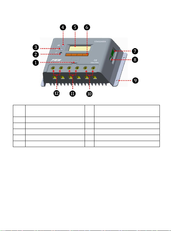
1.2 Characteristics
❶
Battery slot
(battery model is CR2032-3.3V)
❼
RS485 communication port
❷
Local temperature sensor
❽
RTS★port
❸
Fault LED indicator
❾
Mounting Hole Φ4mm
❹
Charging LED indicator
❿
Load Terminals
❺
LCD ⓫ Battery Terminals
❻
Buttons
⓬
PV Terminals
★The controller is charging and discharging at the local temperature sensor when the remote
temperature sensor don’t connect. If the remote temperature sensor is damaged, the controller
will be charging or discharging at the default temperature 25℃.
2
Page 6
2. Installation Instructions
2.1 General Installation Notes
Read through the entire installation section first before beginning installation.
Be very careful when working with batteries. Wear eye protection. Have fresh water available to wash and
clean any contact with battery acid.
Uses insulated tools and avoid placing metal objects near the batteries.
Explosive battery gasses may be present during charging. So well ventilation of battery box is
recommended.
Avoid direct sunlight and do not install in locations where water can enter the controller.
Loose power connections and/or corroded wires may result in resistive connections that melt wire
insulation, burn surrounding materials, or even cause fire. Ensure tight connections and use cable clamps
to secure cables and prevent them from swaying in mobile applications.
Gel, Sealed or Flooded batteries are recommended, other kinds please refer to the battery manufacturer.
Battery connection may be wired to one battery or a bank of batteries. The following instructions refer to a
singular battery, but it is implied that the battery connection can be made to either one battery or a group
of batteries in a battery bank.
Select the system cables according to 3.5A/mm2 current density.
2.2 Installation and Wiring
WARNING: Risk of explosion! Never install the controller in a sealed enclose with
flooded batteries! Do not install in a confined area where battery gassed can
accumulate.
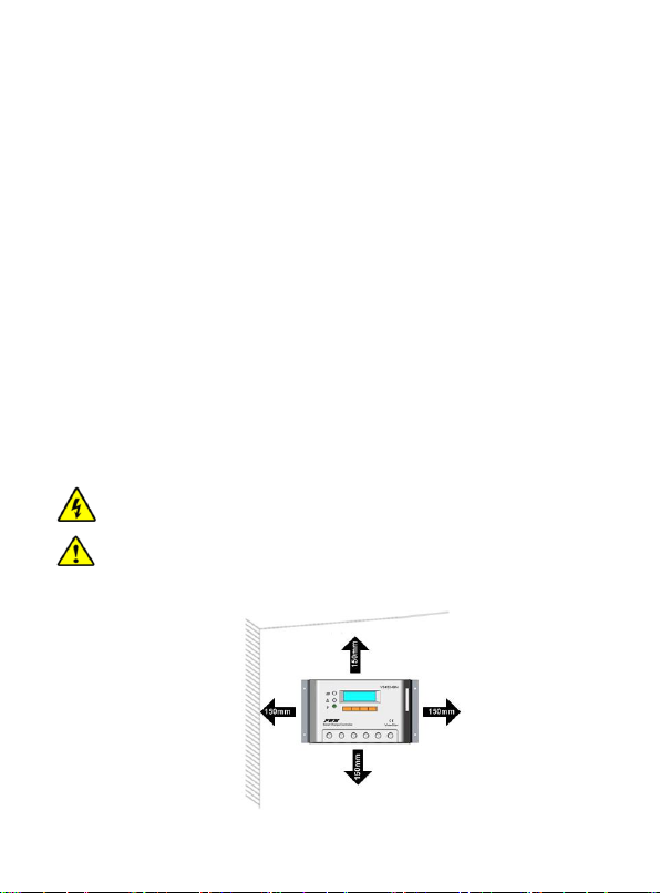
CAUTION: The ViewStar controller requires at least 150mm of clearance above and
below for proper air flow. Ventilation is highly recommended if mounted in an
enclosure.
Installation Procedure:
Figure 2-1 Mounting
3
Page 7
Step 1: Determination of Installation Location and Heat-dissipation Space
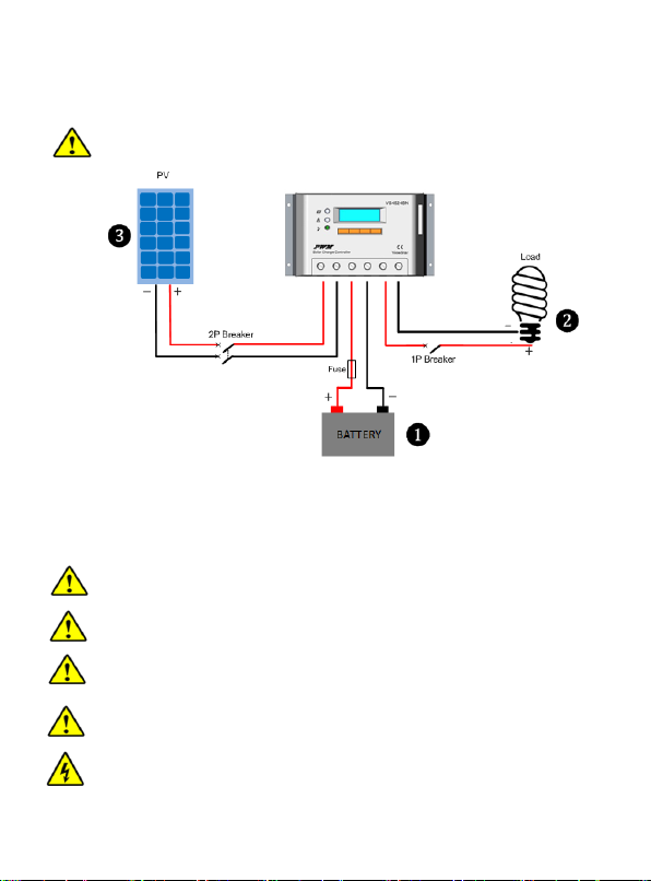
Figure 2-2 Schematic of wiring
Determination of installation location: The controller shall be installed in a place with sufficient air flow
through the radiators of the controller and a minimum clearance of 150 mm from the upper and lower
edges of the controller to ensure natural thermal convection. Please see Figure 2-1: Mounting
CAUTION: If the controller is to be installed in an enclosed box, it is important to ensure
reliable heat dissipation through the box.
Step 2:Connect the system in the order of ❶battery ❷ load ❸PV array in accordance with Figure
2-2,”Schematic Wiring Diagram” and disconnect the system in the reverse order❸❷❶.
CAUTION: While wiring the controller do not close the circuit breaker or fuse and make sure that the
leads of "+" and "-" poles are connected correctly.
CAUTION: A fuse which current is 2 times the rated current of the controller.
NOTE: The controller is common negative one.
CAUTION: Don’t connect the loads with surge power exceeding the ratings.
CAUTION: Secure all wiring for mobile applications. Use cable clamps to prevent cables from
swaying. Unsecured cables create loose and resistive connections which may lead to
excessive heating and fire.
WARNING: Risk of explosion or fire! Never short circuit battery positive (+) and negative (-) or
cables.
4
Page 8
WARNING: Risk of electric shock! Exercise caution when handling solar wiring. The solar
module(s) high voltage output can cause severe shock or injury. Be careful operation when
installing solar wiring.
Step 3:Grounding
VS BN series is a common-negative controller, where all the negative terminals of PV array, battery and
load can be grounded simultaneously or any one of them will be grounded. However, according to the
practical application, all the negative terminals of PV array, battery and load can also be ungrounded,
but the grounding terminal on its shell must be grounded, which may effectively shield the
electromagnetic interference from the outside, and prevent some electric shock to human body due to
the electrification of the shell.
CAUTION: For common-negative system, such as motorhome, it is recommended to use a
common-negative controller; but if in the common-negative system, some common-positive
equipment are used, and the positive electrode is grounded, the controller may be damaged.
Step 4:Powered on the controller
Closing the battery fuse will switch on the controller. Then check the status of the battery indicator (the
controller is operating normally when the indicator is lit in green). Close the fuse and circuit breaker of
the load and PV array. Then the system will be operating in the preprogrammed mode.
CAUTION: If the controller is not operating properly or the battery indicator on the controller
shows an abnormality, please refer to 5.2 “Troubleshooting”.
5
Page 9
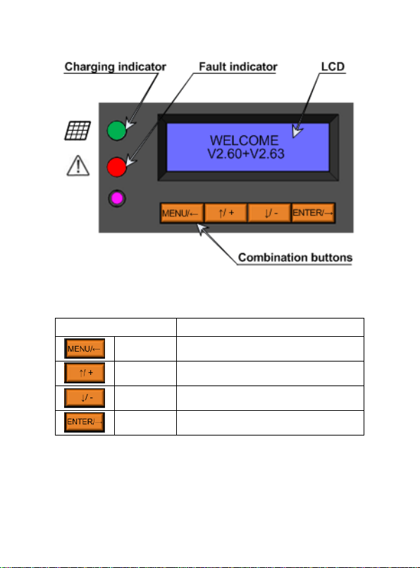
3. HMI Interface
Button
Note
Menu
Cursor left button
Cursor up
Number add button
Cursor down
Number reduce button
Enter
cursor right button
3.1 Button
6
Page 10
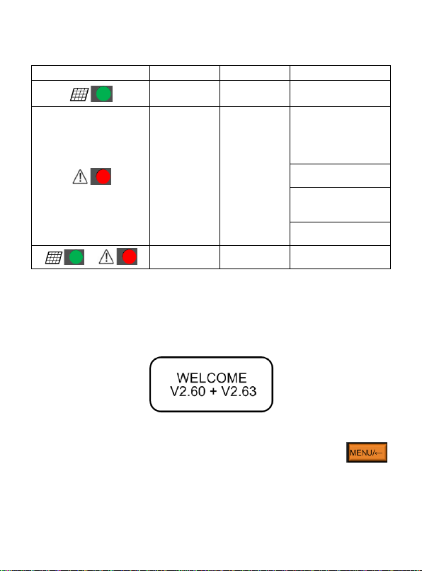
3.2 Indicator
Indicator
Color
Status
Instruction
Green
On Solid
Charging
Red
Flashing
(6Hz)
PV:
Measure Err,
MOS-I Short,
MOS-C Short,
MOS Break
BATT:
OVD,Over Temp
LOAD:
Overload,Short,
MOS Short
DEVICE:
Over Temp
&
Green & Red
Flashing
(6Hz)
BATT:
Rated V Err
3.3 Operation Interface
1) Initialization Interface
When controller is powered on, the following picture will be painted during the initialization:
2) Main Menu Interface
After controller is initialized, the monitoring interface will update automatically. Press button
to main menu 1 interface which displays the following contents:
7
Page 11
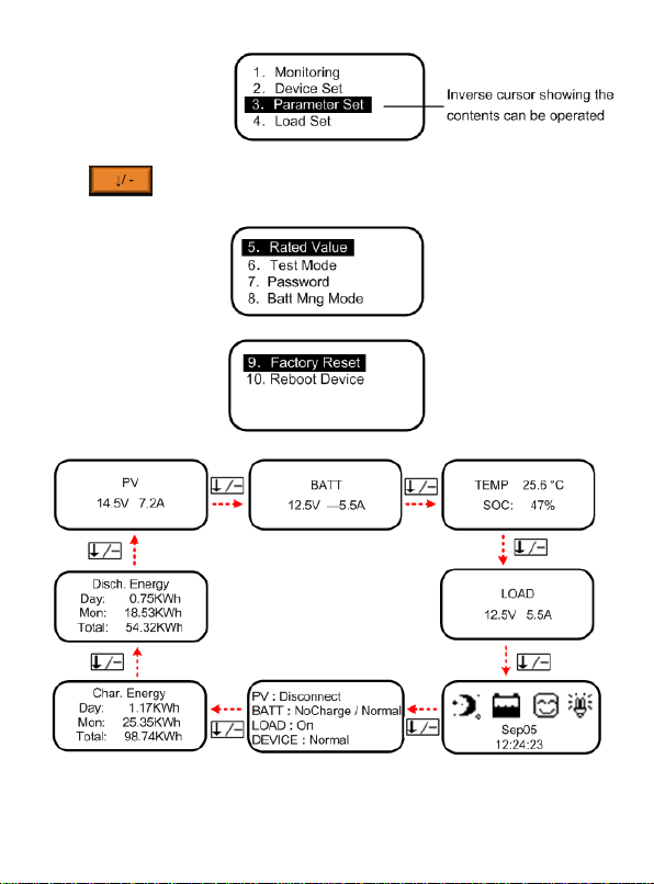
Press button to enter into main menu 2 and main menu 3 interface which displays the
following contents:
3) Monitoring
Display:Solar array voltage and current→Battery voltage and current→Battery temperature and battery
SOC→Load voltage and current→Real-time clock and imaging system status→System status→
Charging energy statistics→Discharging energy statistics
8
Page 12
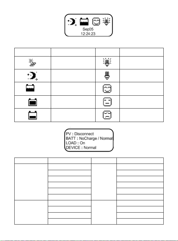
System status icons:
Icons
Status
Icons
Status
Day ON
Night OFF
▲
Charging
Normal
Normal UVW
LVD LVD
System
Status
System
Status
PV
Connect
BATT
LVD
Measure Err★
Normal
MOS-C Short★
Rated V Err★
Disconnect
UVW
MOS-I Short★
OVD★
MOS Break★
OverTemp★
BATT
charging status
Equalize
LOAD
On
Float
OverLoad★
Boost
Off
No Charge
Short★
▲Icons indicating battery charging are dynamic effects.
System status :
9
Page 13
DEVICE
Normal
MOS Short★
OverTemp★
★When fault with inverse cursor above exists for 2 minutes along without any operation, it will
Parameter
Detail
ID
Range:1~200
Clock
Format:dd-mm-yyyy hh-mm-ss
Password
Default:000000
jump into that page automatically.
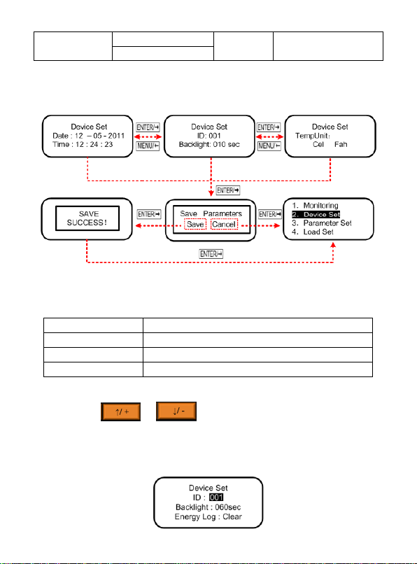
4) Device Set
Display:Date set→ID and LCD backlight time set→TempUnit set
Device parameters
Clear Energy
Press and hold both and button for 3 seconds to enter factory mode in the main
interface. The authority code to clear Energy Log is 102206 as default. The clear operation can’t be
recalled, so take care!
10
Page 14
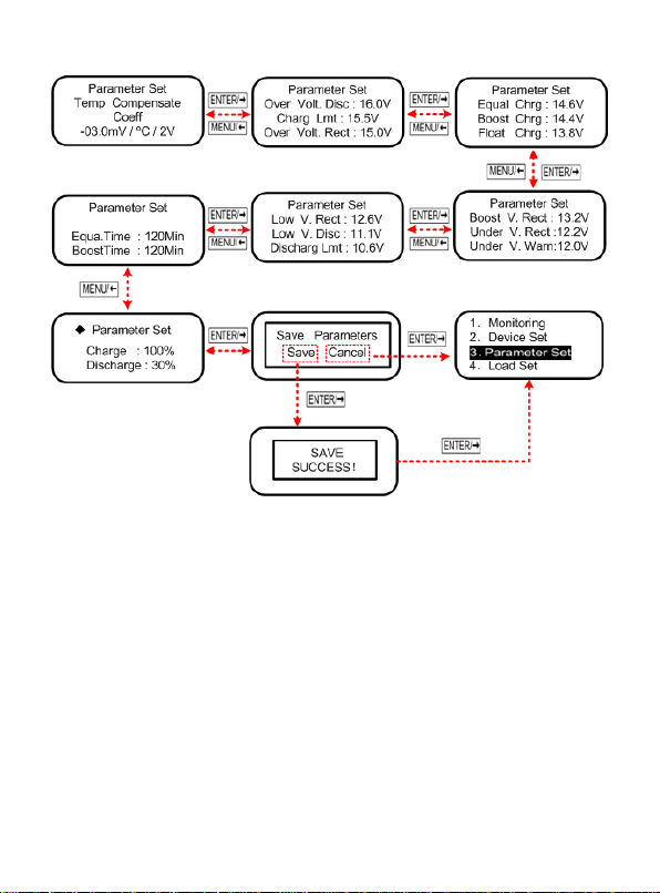
5) Parameter Set
◆The interface will prompt only when the SOC is selected in the Batt Mng Mode.
Display:Temperature compensation coefficient→Control parameters interface 1/2/3/4/5
11
Page 15
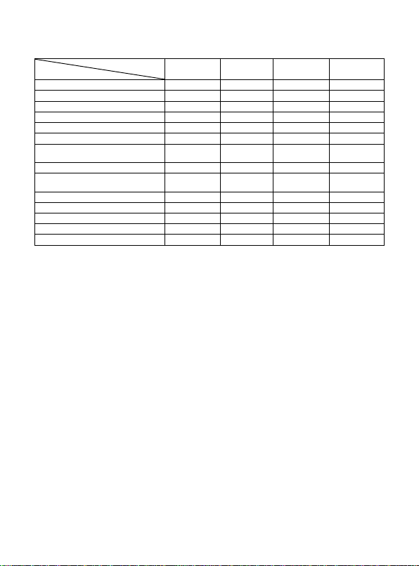
Lead-acid battery parameters
Battery type
Voltage
Sealed
Gel
Flooded
User
Over Voltage Disconnect Voltage
16.0V
16.0V
16.0V
9~17V
Charging Limit Voltage
15.0V
15.0V
15.0V
9~17V
Over Voltage Reconnect Voltage
15.0V
15.0V
15.0V
9~17V
Equalize Charging Voltage
14.6V
——
14.8V
9~17V
Boost Charging Voltage
14.4V
14.2V
14.6V
9~17V
Float Charging Voltage
13.8V
13.8V
13.8V
9~17V
Boost Reconnect Charging
Voltage
13.2V
13.2V
13.2V
9~17V
Low Voltage Reconnect Voltage
12.6V
12.6V
12.6V
9~17V
Under Voltage Warning
Reconnect Voltage
12.2V
12.2V
12.2V
9~17V
Under Voltage Warning Voltage
12.0V
12.0V
12.0V
9~17V
Low Voltage Disconnect Voltage
11.1V
11.1V
11.1V
9~17V
Discharging Limit Voltage
10.6V
10.6V
10.6V
9~17V
Equalize Duration
120 min
——
120 min
0~180 min
Boost Duration
120 min
120 min
120 min
10~180 min
The parameters are in 12V system at 25 ºC, please double the values in 24V system.
Note:
1)When the battery type is sealed, gel, flooded,the adjusting range of equalize duration is 0 to180min
and boost duration is 10 to180min.
2)The following rules must be observed when modify the parameters value in user battery type(factory
default value is the same as sealed type):
a. Over Voltage Disconnect Voltage > Charging Limit Voltage ≥Equalize Charging Voltage ≥Boost
Charging Voltage ≥Float Charging Voltage > Boost Reconnect Charging Voltage;
b. Over Voltage Disconnect Voltage > Over Voltage Reconnect Voltage;
c. Low Voltage Reconnect Voltage > Low Voltage Disconnect Voltage≥Discharging Limit Voltage;
d. Under Voltage Warning Reconnect Voltage > Under Voltage Warning Voltage ≥Discharging Limit
Voltage;
e. Boost Reconnect Charging Voltage > Low Voltage Reconnect Voltage.
12
Page 16
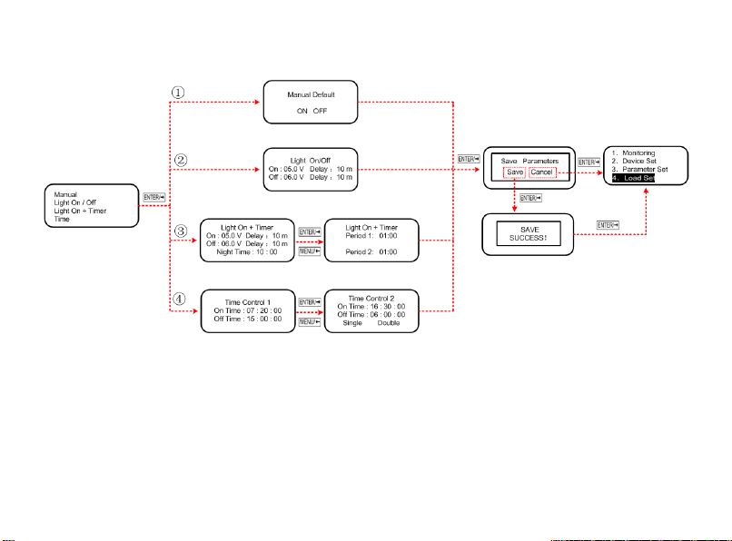
6) Load Set
Display:①Manual /②Light On/Off /③Light On+Timer /④Time
Threshold voltage value
Night Time Threshold Voltage: 6V/12V,12V/24V
Day Time Threshold Voltage: 5V/12V,10V/24V
13
Page 17
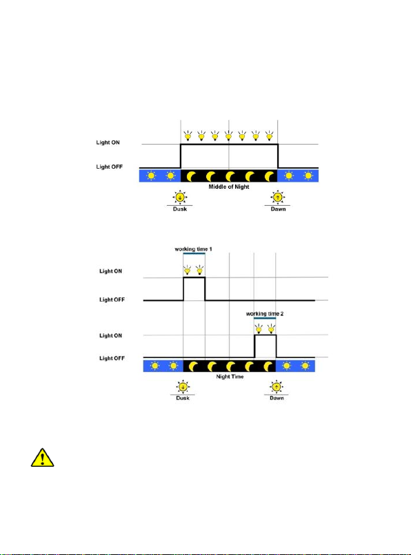
Load working mode
1. Manual(default)
Control ON/OFF of the load via the button or remote commands.
2.Light ON/OFF
3.Light ON+Timer
4.Time
Control the load ON/OFF time through setting the real-time clock.
NOTE: In the mode of Light ON/OFF and Light ON/Timer, the Load is turned on after
10Min. delay.
14
Page 18
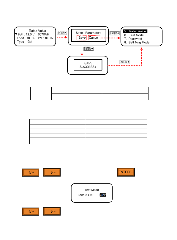
7) Rated Value
Batt
System nominal voltage
Battery capacity range
12V/24V/Auto
Range :0~9999AH
Battery Type
Note
Sealed (default)
Constant value▲
GEL
Constant value▲
Flooded
Constant value▲
User
Defined by user▲
▼ System Nominal Voltage and Battery Rate Setting
Battery Type
▲The parameters refer to the Lead-acid battery parameters (Parameter Set).
8) Test Mode
Press or ,choose the Test Mode,then press and enter into test
mode interface below:
Press or ,when the inverse cursor stays ON/OFF,that is test on or test off
operations.
15
Page 19
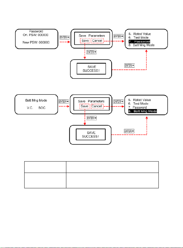
9) Password
Precent of charging
100% constant value
Precent of discharging
10~80%, Low SOC reconnect is higher Low SOC
disconnect than 5%
10) Batt Mng Mode
SOC parameters
16
Page 20
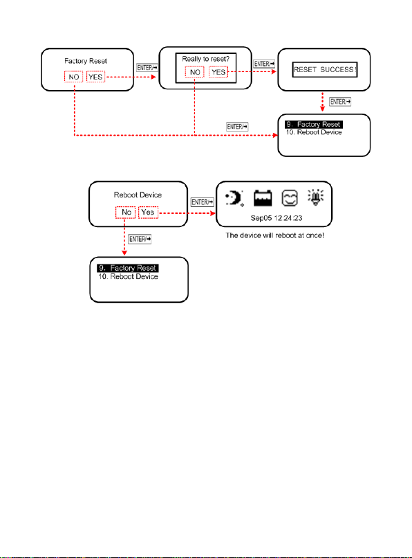
11) Factory Reset
12) Reboot Device
17
Page 21
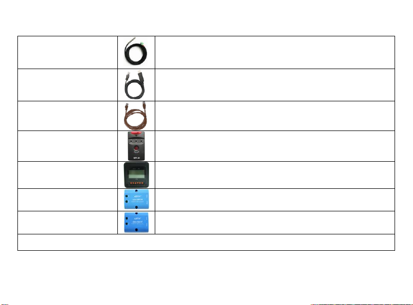
4. Accessories (optional)
Remote Temperature Sensor
(RTS300R47K3.81A)
Acquisition of battery temperature for undertaking temperature compensation of control
parameters, the standard length of the cable is 3m (length can be customized). The
RTS300R47K3.81A connects to the port (8th) on the controller.
NOTE: The temperature sensor short-circuited or damaged, the controller will be
charging or discharging at the default temperature 25 ºC.
USB to RS485 cable
CC-USB-RS485-150U
USB to RS485 converter is used to monitor each controller using Solar Station PC software.
The length of cable is 1.5m. TheCC-USB-RS485-150U connects to the RS485 Port on the
controller.
RS485 to RS485 cable
CC-RS485-RS485-200U
RS485 to RS485 converter is used to connect the accessories
SPP-02,MT50,eBox-WIFI-01,eBox-BLE-01,the standard length of the cable is 3m (length
can be customized).
Super Parameter Programmer
SPP-02
SPP-02 can realize one-key setting parameter operation.
Remote Meter
MT50
MT50 can display various operating data and fault info the system. The information can be
displayed on a backlit LCD screen, the buttons are easy-to-operate, and the numeric display
is readable.
WIFI Serial Adapter
eBox-WIFI-01
After the controller is connected with the eBox-WIFI-01 through the standard Ethernet cable
(parallel cable), the operating status and related parameters of the controller can be
monitored by the mobile APP software through WIFI signals.
RS485 to Bluetooth Adapter
eBox-BLE-01
After the controller is connected with the eBox-BLE-01 through the standard Ethernet cable
(parallel cable), the operating status and related parameters of the controller can be
monitored by the mobile APP software through Bluetooth signals.
NOTE: For setting and operation of accessory, please refer to accessory’s user manual.
18
Page 22
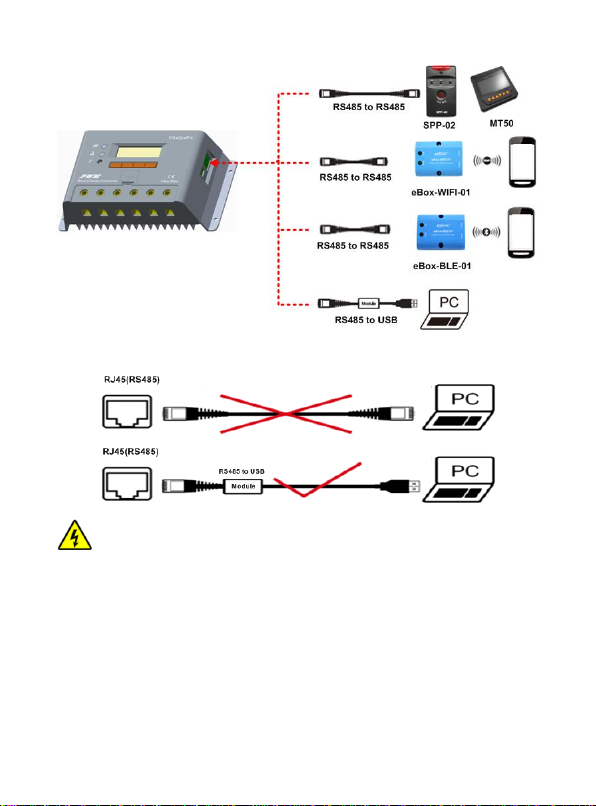
WARNING: Do not use the standard twisted-net cable to connect the device and PC
net interface, or the permanent damage will occur.
19
Page 23
5. Protections, Troubleshooting and Maintenance
PV Short Circuit
When not in PV charging state, the controller will not be damaged in case of a short-circuiting in the PV
array.
PV Reverse Polarity
When the polarity of the PV array is reversed, the controller may not be damaged and can continue to
operate normally after the polarity is corrected.
PV Over Voltage
When the PV voltage is higher 60V, the controller will cut off the charging automatically, and when the
voltage is lower than 55V, the controller will recover charging. automatically
Charging Battery Cut Off
Disconnect the battery when the controller is charged at rated power , the controller do not be damaged
Load Overload
When the load is overloading (The overload current is ≥ 1.05 times the rated load current), the controller
will automatically cut off the output. If the load reconnects automatically, it needs to be cleared by
pressing the Load button restarting the controller.
Load Short Circuit
Fully protected against load wiring short-circuit(≥2 times rated discharge current). After five automatic
load reconnect attempt, the fault must be cleared by restarting the controller or pressing the switch
button.
Damaged Temperature Sensor
If the temperature sensor short-circuited or damaged, the controller will be charging or discharging at the
default temperature 25℃ to prevent the battery damaged from overcharging or over discharged.
Controller Overheating
The controller is able to detect the temperature inside the battery. The controller stops working when its
temperature exceeds 85 °C and restart to work when its temperature is below 75 °C.
TVS High Voltage Transients
The internal circuitry of the controller is designed with Transient Voltage Suppressors (TVS) which can
only protect against high-voltage surge pulses with less energy. If the controller is to be used in an area
with frequent lightning strikes, it is recommended to install an external surge arrester.
5.1 Protection
20
Page 24

5.2 Troubleshooting
Faults
Possible reasons
Troubleshooting
Charging LED indicator is off during
daytime and the monitor shows
Disconnect.
PV Array Disconnection
Check that PV and battery wire connections are correct and
tight.
Monitor interface PV shows Measure
Err, MOS-I Short, MOS-C Short, MOS
Break.
Fault indicator flashing
MOS-I Or MOS-C Damage
Please restart controller;
if the fault still exists, switch off controller immediately and
contact the supplier to make maintenance.
Monitor interface BATT shows LVD.
Battery Over Discharged
The controller cut off the output automatically and recover when
fully charged.
Charging and discharging circuit is off
and monitor interface BATT shows OVD.
Fault indicator flashing
Battery Over Voltage
switch off the wiring of solar array and measure the voltage of
battery whether is too high.
Charging and discharging circuit is off
and the BATT of monitoring interface
shows Over Temp.
Fault indicator flashing
Operating Ambient
Temperature
(local temperature sensor) Or
Battery Temperature
(remote temperature sensor)
Over Temperature
When operating ambient temperature or battery temperature
reaches exceeds 65ºC controller will cut off input and output
circuit automatically.
When the temperature is below 55℃, controller will
automatically reconnect input and output circuit.
Monitor interface BATT shows Rated V
Err.
Charging indicator and Fault indicator
flashing
System Voltage Error
Check whether the battery voltage is consistent with the system
voltage set by the controller.
Discharging circuit is off and monitor
shows Over Load.
Fault indicator flashing
Load Overload▽
①Please reduce the number of electric equipments.
②Restart the controller.
Discharging circuit is off and the LOAD
monitor shows Short.
Fault indicator flashing
Load circuit is short
①Check carefully loads connection, clear the fault.
②Restart the controller.
Charging and discharging circuit is off
Electronical Component
Please restart controller, if the fault still exists, cut off charging
21
Page 25
and the LOAD of monitoring interface
shows MOS-I Short,Error.
Fault indicator flashing
Damage
and discharging circuit immediately and contact the supplier to
make maintenance.
Charging and discharging circuit is off
and the LOAD monitor shows Over
Temp.
Fault indicator flashing
Controller Overheating
When the temperature of controller exceeds 85℃, the
controller will cut input and output circuit. when it is below
75℃,the controller will automatically reconnect input and output
circuit.
▽When load power reaches 1.02-1.05 times, 1.05-1.25 times, 1.25-1.35 times, 1.35-1. 5 times more than nominal value, controller will
automatically close loads in 50 seconds, 30 seconds, 10 seconds and 2 seconds, respectively.
5.3 Maintenance
The following inspections and maintenance tasks are recommended at least two times per year for best performance.
Check that the air flow and ventilation around the controller is not blocked. Clear all dirt or fragments on the heat sink.
Check all the naked wires to make sure insulation is not damaged for serious solarization, frictional wear, dryness, insects or rats etc. Maintain or
replace the wires if necessary.
Check and confirm that LED or LCD is consistent with required. Pay attention to any troubleshooting or error indication .Take corrective action if
necessary.
Tighten all the terminals. Inspect for loose, broken, or burnt wire connections.
Confirm that all the terminals have no corrosion, insulation damaged, high temperature or burnt/discolored sign, tighten terminal screws to the
suggested torque.
Inspect for dirt, insects and corrosion, and clear up.
Check and confirm that lightning arrester is in good condition. Replace a new one in time to avoid damaging of the controller and even other
equipments.
NOTE: Dangerous with electric shock!
Make sure that all power source of controller is cut off when operate above processes, make inspection or other operations!
22
Page 26

6. Technical Specifications
Item
VS4524BN
System nominal voltage
12∕24VDC Auto
Battery voltage range
9V ~32V
Max. PV open circuit voltage
60V
Rated charge current
45A
Rated discharge current
45A
Charge circuit voltage drop
≤0.69V
Discharge circuit voltage drop
≤0.17V
Battery type
Sealed / Gel / Flooded / User
Temperature compensate coefficient
-3mV∕℃∕2V(25℃)
Self-consumption
≤15mA/12V; ≤13mA/24V
RS485 interface
RS485(RJ45)
Remote temperature sensor interface
2P—3.81
Grounding
Negative
LCD temperature range
-20℃~ +70℃
Working environment temperature range
-25℃~ +50℃
Storage temperature range
-30℃~ +85℃
Relative humidity
≤95%,N.C.
Enclosure
IP30
Terminal
2AWG(35 mm2)
Weight
0.64 kg
23
Page 27
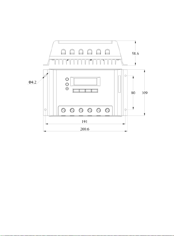
Annex Mechanical Dimension Diagram
VS4524BN(Unit:mm)
Any changes without prior notice! Version number: 1.0
24
Page 28

BEIJING EPSOLAR TECHNOLOGY CO., LTD.
Tel: +86-10-82894112 / 82894962
Fax: +86-10-82894882
E-mail:[email protected]
Website: http://www.epsolarpv.com/
http://www.epever.com/
 Loading...