

Page 1
INSTRUCTION MANUAL
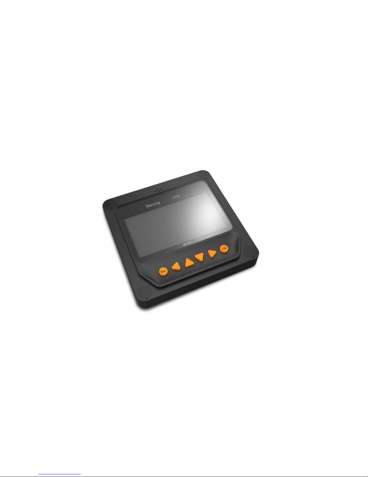
Remote Meter: MT50
Thank you very much for selecting our product!
This manual offers important information and suggestions with respect to
installation, use and troubleshooting, etc. Please read this manual carefully before
using th e product.
Page 2

Page 3

Remote Meter
MT50
Remote meter (Model MT50) is available to connect with solar
controller LSxxxxB(P), VSxxxxBN and TracerxxxxBN(P).
Page 4

Contents
1 Important Safety Instructions ............................................................... 1
2 General Information ............................................................................ 2
2.1 Features .............................................................................................. 2
2.2 Main functions ................................................................................... 3
2.3 Recommendations ............................................................................ 3
3 Installation........................................................................................... 4
4 Product Features ................................................................................ 8
5 Operation ......................................................................................... 12
5.1 Buttons ............................................................................................... 12
5.2 Main menu ......................................................................................... 13
5.3 Real-time monitoring ...................................................................... 14
5.4 Device information ........................................................................... 16
5.5 Test operation .................................................................................. 16
5.6 Control parameter ........................................................................... 17
5.7 Load setting ..................................................................................... 21
5.8 Device parameter ........................................................................... 24
5.9 Device password ............................................................................. 25
5.10 Factory reset ................................................................................... 25
5.11 Failure information .......................................................................... 26
5.12 Meter parameter ............................................................................. 27
6 Technical Specifications .................................................................... 28
Page 5

1
1 Important Safety Instructions
SAVE THESE INSTRUCTIONS:
This manual contains important safety, installation and operating
instructions for the Remote Meter.
General safety information
■
Please inspect the MT50 thoroughly after it is delivered. If any damage is
seen, please notify the shipping company or our company immediately. A
photo of the damage may be helpful.
■
Read all instructions and cautions in the manual before starting the
installation.
■
Keep the MT50 away from rain, exposure, severe dust, vibrations, corrosive
gas and intense electromagnetic interference.
■
Do not allow water to enter remote meter.
■
There are no user serviceable parts inside the controller. Do not
disassemble or attempt to repair it.
Page 6

2
2 General Information
2.1 Features
The new-generation remote display unit MT50 for LSxxxxB(P), VSxxxxBN
and TracerxxxxBN(P) controllers is an associated display device which
supports both the latest communication protocol and the voltage technology
standard of solar controllers. The products have many excellent functions:
■
Automatic identify and display the type, model and relevant parameter
data of controllers;
■
Real-time display the operational data and working status of the connection
devices in digital, graphic and textual forms by a large-screen multifunction
LCD;
■
Direct, convenient and rapid operation of six navigation function keys;
■
Both data and power flowing on th e same lead, no need for external power;
■
Real-time data monitoring and remote load switchover of the controllers,
and data browse and modification of device parameters, charge control
parameters and load control parameters;
■
Real-time display and acoustic alarm of failure information of the
connection devices;
■
Longer communication distance based on RS485.
Page 7

3
2.2 Main functions
Functions like the real-time monitoring of the operational data and working
status of a controller, the browse and modification of charge/discharge
control parameters, the setting of device parameters and load control
parameters and the restoration of factory defaults, based on LCD display
and functional key operation.
2.3 Recommendations
■
Please confirm that MT50 is only allowed to connect with our
LSxxxxB(P), VSxxxxBN and TracerxxxxBN(P) series controllers before
purchase;
■
Please do not install MT50 in a situation with strong electromagnetic
interference.
Page 8
4
3 Installation
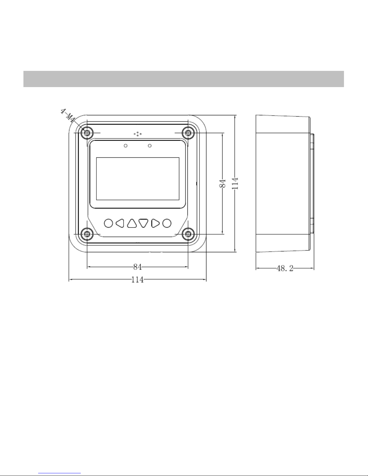
Frame Mount Dimensions(
mm)
Page 9
5
Mechanical
parameter
Parameter
Overall
dimension
114 x 114 x 48.2mm
Mounting
dimension
84x 84mm
Terminal
Φ5
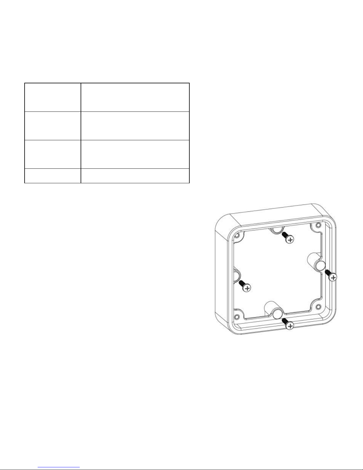
Wall installation steps:
Step1: Locate and drill screw holes
based on the Frame Mounting dimension
of the base, and erect the plastic
expansion bolts;
Step 2: Use four ST4.2×32 self-tapping
screws to fix the Frame;
Frame Mounting
Page 10
6
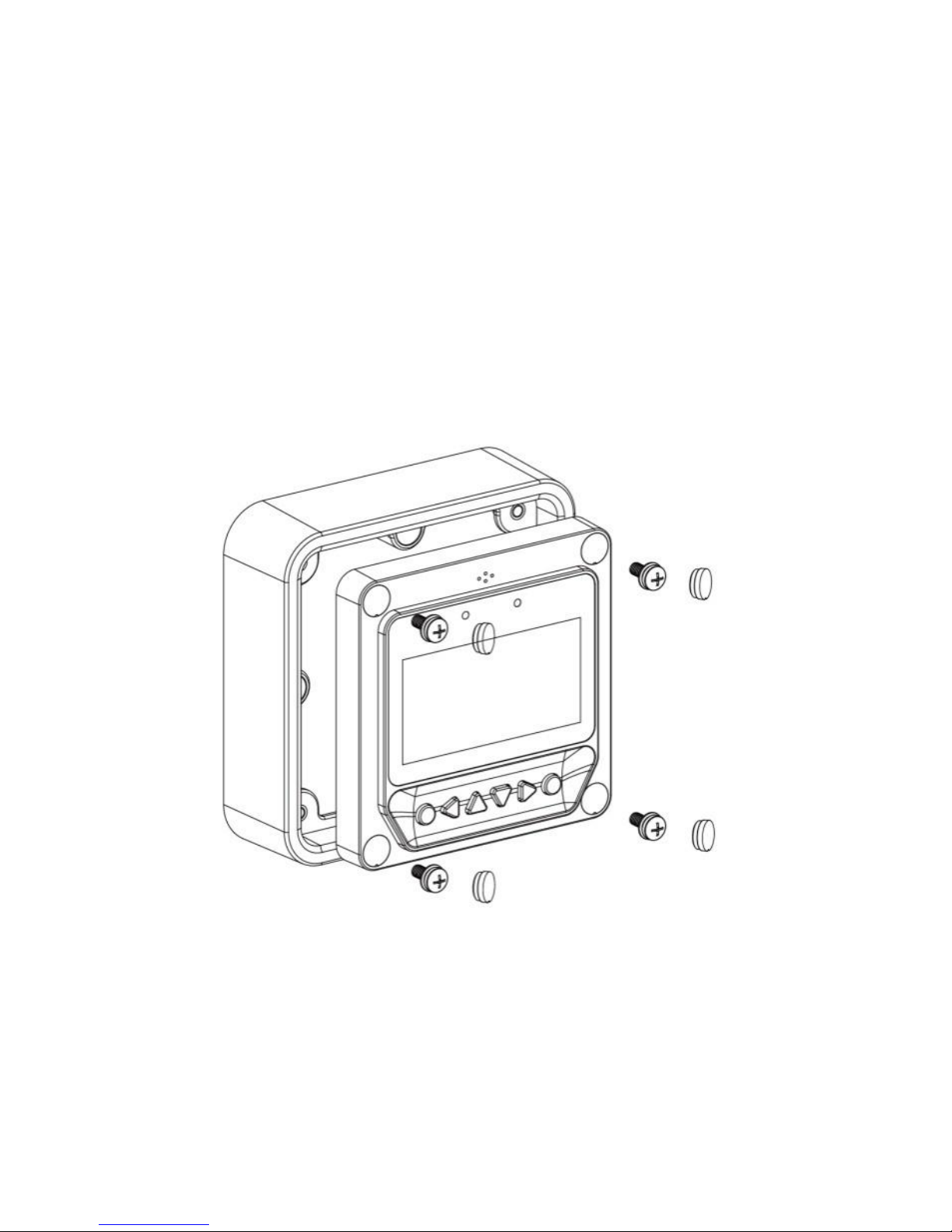
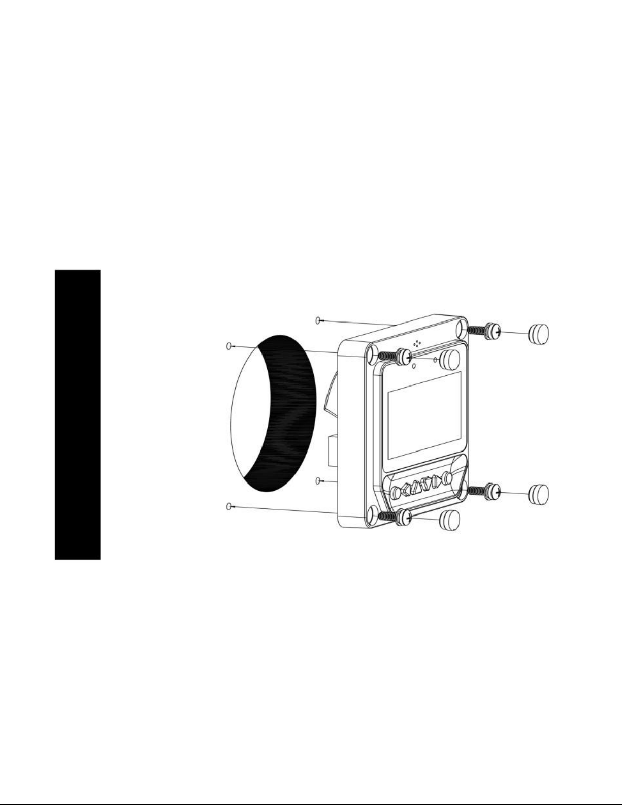
Step 3: Use four M4×8 pan head screws to mount MT50 Surface on the
Frame;
Step 4: Mount the four associated screw plugs into the screw holes.
Surface Mounting
Page 11
7
Steps of surface mounting:
Step 1: Locate and drill screw holes based on the installation size of the
Surface;
Step 2: Use four M4×8 cross recessed pan head screws with M4 nuts to
mount MT50 Surface onto the panel;
Step 3: Mount the four associated white screw plugs into the screw holes.
Surface mounting
Note: Take full consideration of the plugging/unplugging space of the
communication cable and the length of the cable during installation to
see if they are appropriate.
Page 12
8
4 Product Features
Page 13
9
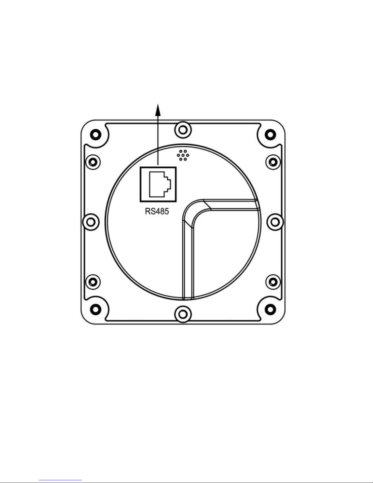
RS485 communication and power interface
Rear View
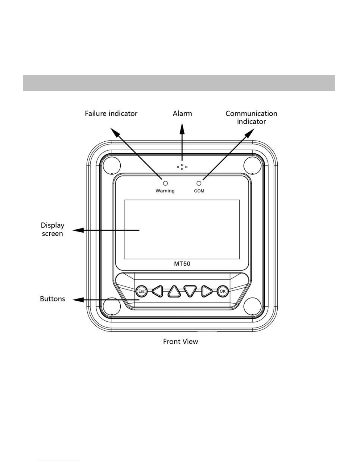
Failure indicator
Failure indicator flashes in case of failure of the connection devices.
For failure information please check the Controller Manual.
Page 14
10
Alarm
Fault audible alarm, could be activated or deactivated.
Communication indicator
Indicate communication status when MT50 is connected with the controller.
Display screen
Man-machine interaction operation interface.
Buttons
The Meter buttons includes four navigation buttons and two operational
buttons. See the specific directions in the Operational Manual.
RJ45 communication and power interfaces
Communication and power supply cable interfaces, used for communication
connection with controllers.
Note: Please use the communication plug which is marked with “MT”
to connect MT50
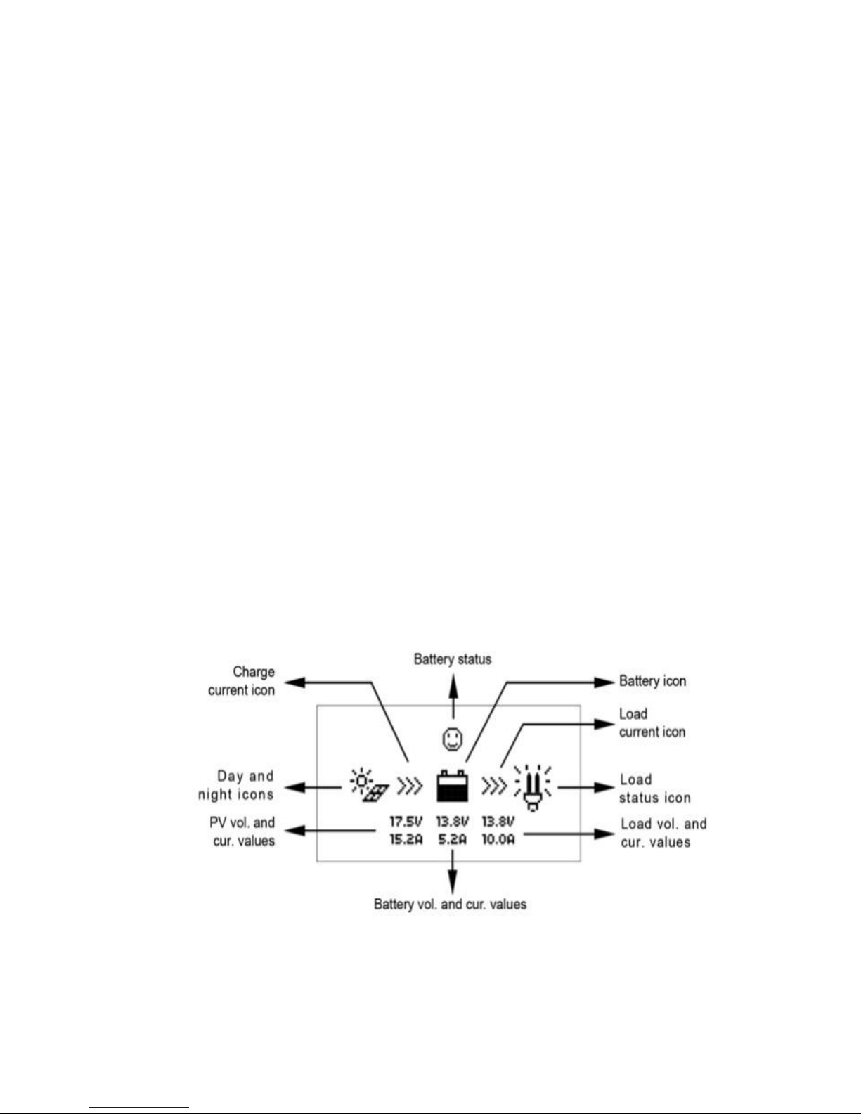
Monitoring screen
Page 15
11
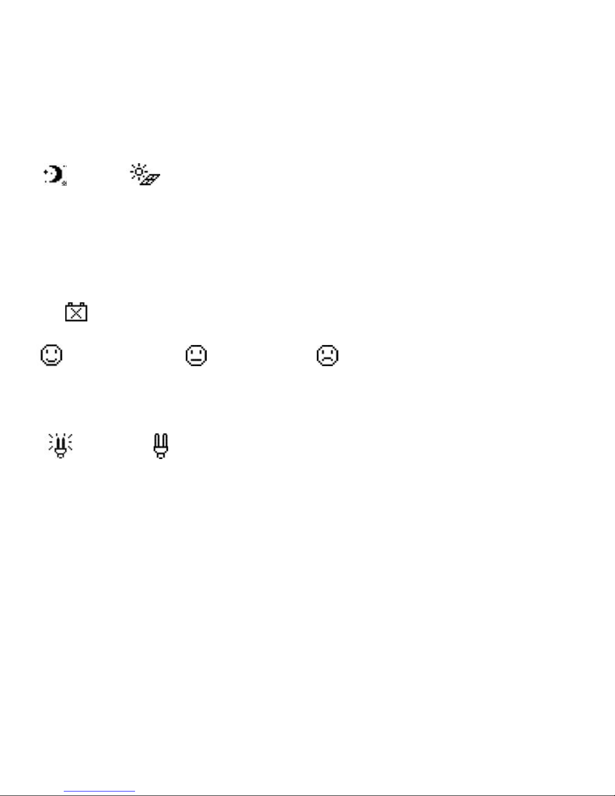
Day and night icons
-Night
,
- Day: The threshold voltage is 1V. Higher than 1V is daytime.
Charge current icon
The icon is dynamically if there is charge current.
Battery icon
The battery capacity is dynamically displayed
Note: When the battery is in over discharge status, the icon displayed
is“ ”.
Battery status icons
-Normal voltage, -Under voltage, -Over discharge.
Load current icon
The icon is dynamically if there is discharge current.
Load status icon
- Load On, - Load Off.
Note: In Manual Mode, pressing the "OK" button will switch the load status
between "ON" and "OFF"
Page 16
12
5 Operation
5.1 Buttons
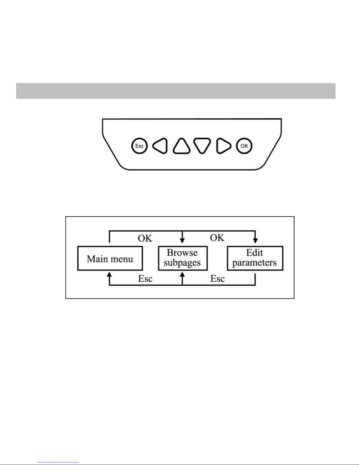
The buttons are respectively (from left to right) “ESC”, “Left”, “Up”, “Down”,
“Right” and “OK “buttons, the operation is described in the schematic
operation diagram below:
Schematic operation diagram
Page 17
13
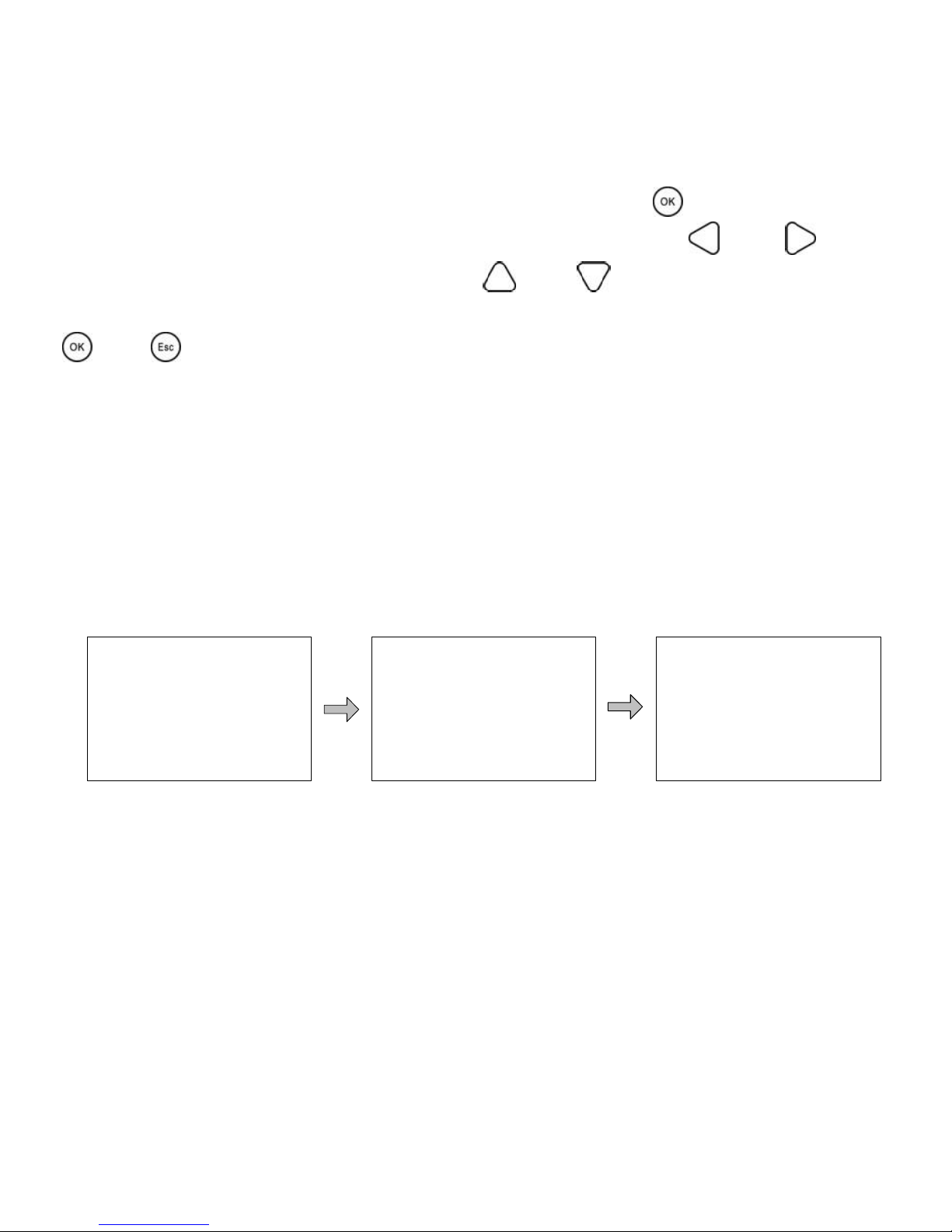
The default entry page is the browse mode. Pressing button and inputting
the correct password to enter the modification mode; and buttons
could be used to move the cursor, and buttons could be used to
modify the parameter values when the cursor is located at the current place;
and buttons could be finally used to respectively confirm and cancel
the modification of the control parameters.
5.2 Main menu
Enter the Main Menu by pressing "Esc". “Up” and “Down” buttons are
respectively used to move the cursor to select the menu items, “OK” and
“ESC” buttons are respectively used to enter or exit the corresponding
pages of the menu items.
1. Monitoring
2. Device Info.
3. Test Operation
4. Control Para.
5. Load Set
6. Device Para
7. Device PSW.
8. Factory Reset
9. Failure Info.
10. Meter Para.
Page 18
14
5.3 Real-time monitoring
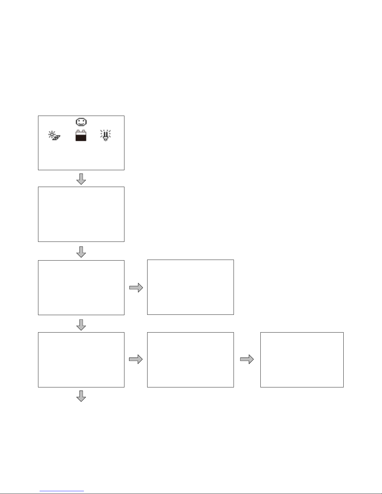
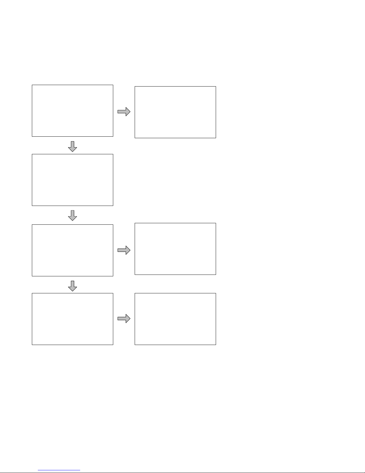
There are 14 pages under real-time monitoring. Please check it as below:
17.5V 13.8V 13.8V
15.2A 5.2A 10.0A
LS****B
Jan-01-2013
02:34:33
Char. Energy
Day: 0.00kwh
Mon: 0.00kwh
Total: 0.00kwh
DisCh. Energy
Day: 0.00kwh
Mon: 0.00kwh
Total: 0.00kwh
Battery
Charge: NoCharge
Energe: Normal
Fault: No
Battery
Vol: 0.0V
Cur: 0.0A
Battery
Temp.: 22.4℃
Max. Vol: 12.7V
Min. Vol: 12.7V
Page 19
15
PV
Sta.: DisConnect
Fault: No
Char.: PWM/MPPT
Load
Sta.: OFF
Fault: No
Load Mode
Information
Load Mode
Information
Load
Vol: 0.0v
Cur: 0.0A
Power: 0.0W
PV
Vol: 0.0V
Cur: 0.0A
Power: 0.0W
Controller
Temp.: 25.0℃
Sta.: Normal
Operational tips:
Move between rows by pressing "Up" or "Down" buttons. Move along a row by
pressing "Right" or "Left" buttons.
Page 20
16
5.4 Device information
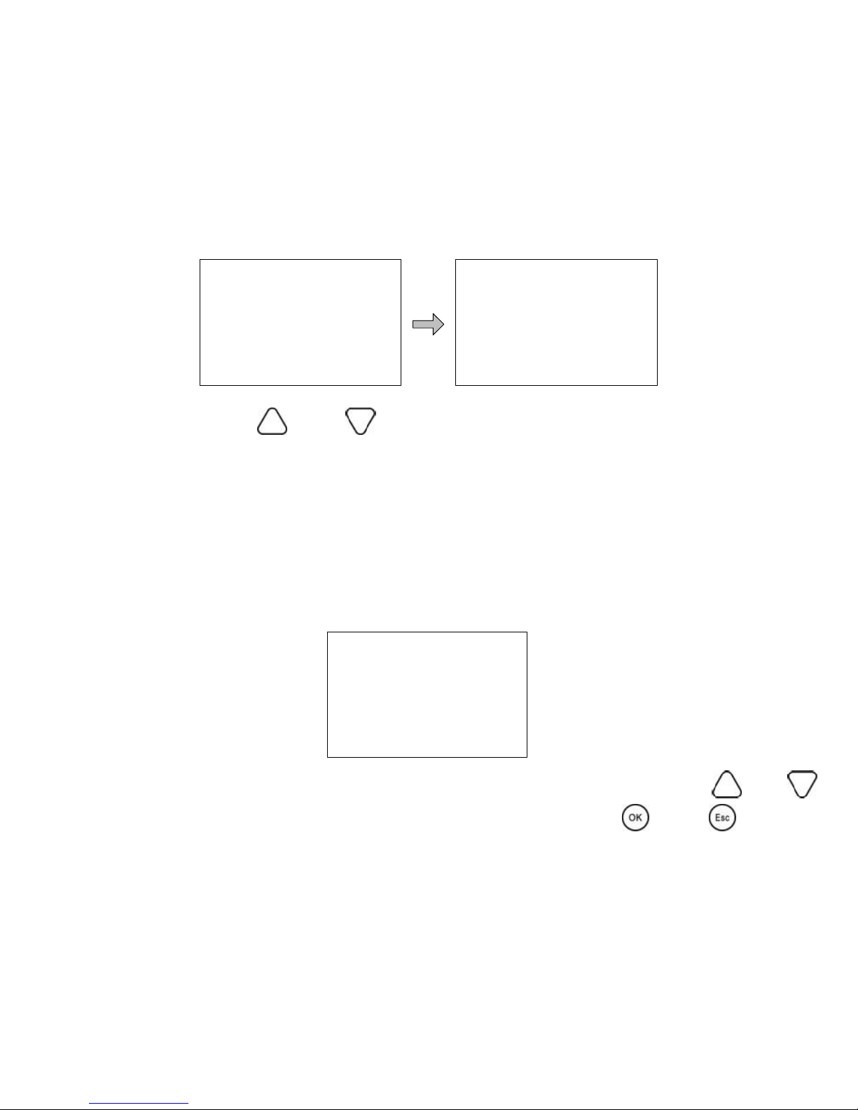
The product model, parameters and SN code of the controllers are displayed
below:
Operational tips: and buttons are respectively used to turn the
browse page upward and downward.
5.5 Test operation
Load switch test operation is conducted on the connection solar controller
to see if the load output is normal. The test operation does not affect the
working settings under actual load, which means that the solar controller will
exit from the test mode when exiting the operational interface of the test.
Test Operation
LS****B: OFF
Operational tips: Enter the page and input correct password; use and
buttons to modify the On/Off status values, while use and buttons
respectively to confirm and cancel the test operation.
LS****B
Rate.Vol: 12V
Char.Cur: 10.0A
Disc.Cur: 2.6A
LS****B
SN:0002201301200045
Page 21
17
5.6 Control parameter
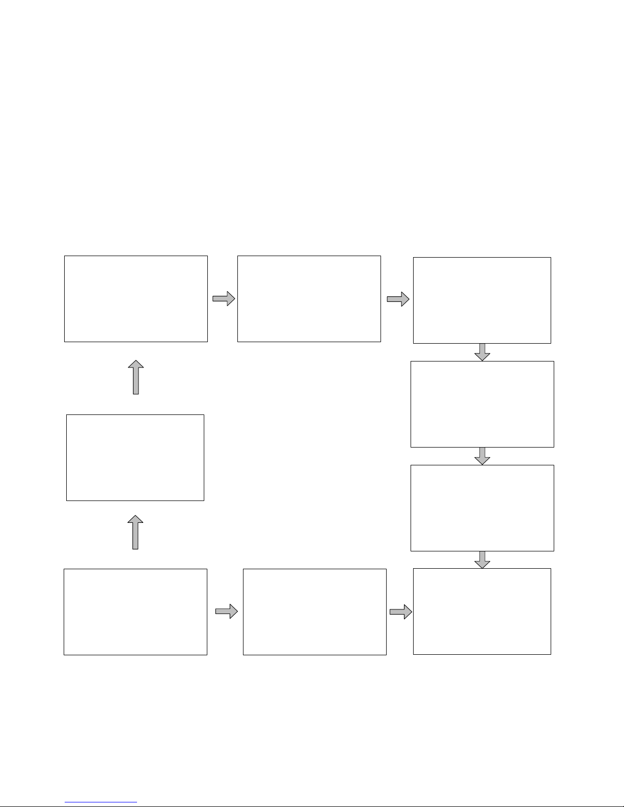
Browse and modification operations are conducted over the control
parameters of solar charge controller. See the scope of parameter
modification in control parameters table, and the page of control parameters
in the diagram below:
Over Volt. Disc
16.0V
Charge Limit
15.0V
Batt. Type
Sealed
Batt. AH
200AH
Temp Comp.Coeff
-3mv/℃/2V
Rated Voltage
12V
Boost Rec.
13.2V
Low Volt. Rect.
12.6V
Ooer Volt. Rec.
15.0V
Eugal. Charge
14.6V
Boost Charge
14.4V
Float Charge
13.8V
Equalize Time
120min
Boost Time
120min
Under Volt. Rect
12.2V
Under Volt. Warn
12.0V
Low Volt. Disc
11.1V
Discharge Limit
10.6V
Page 22
18
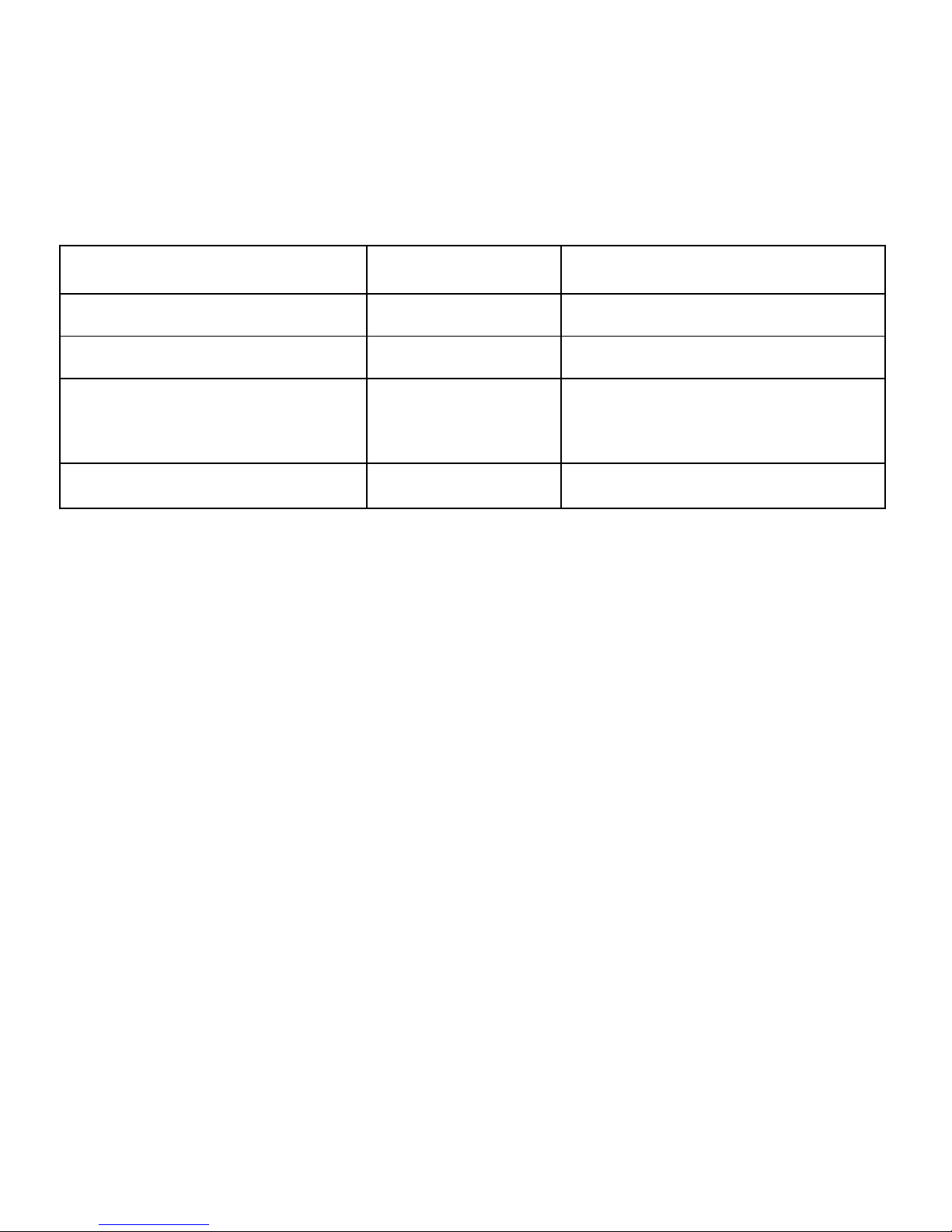
Control parameters table
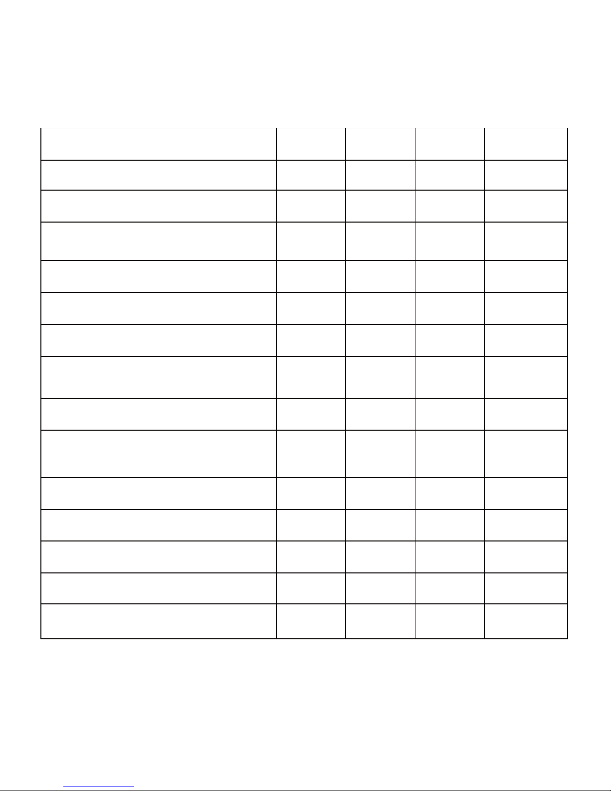
Parameters
Default
Range
Battery type
Sealed
Sealed/Gel/Flooded/User
Battery Ah
200Ah
1~9999Ah
Temperature
compensation coefficient
-3mv/℃/2V
0~-9mv
Rated voltage
Auto
Auto/12V/24V/36V/48V
Battery voltage parameters
(Parameters is in 12V system at 25℃ , please use X 2 in 24V, X 3 in 36 V, and X
4 in 48 V system)
Page 23
19
Battery charging setting
Sealed
Gel
Flooded
User
Over voltage disconnect voltage
16.0V
16.0V
16.0V
9~17V
Charging limit voltage
15.0V
15.0V
15.0V
9~17V
Over voltage reconnect voltage
15.0V
15.0V
15.0V
9~17V
Equalize charging voltage
14.6V
——
14.8V
9~17V
Boost charging voltage
14.4V
14.2V
14.6V
9~17V
Float charging voltage
13.8V
13.8V
13.8V
9~17V
Boost reconnect charging
voltage
13.2V
13.2V
13.2V
9~17V
Low voltage reconnect voltage
12.6V
12.6V
12.6V
9~17V
Under voltage
warning reconnect voltage
12.2V
12.2V
12.2V
9~17V
Under voltage warning voltage
12.0V
12.0V
12.0V
9~17V
Low voltage disconnect voltage
11.1V
11.1V
11.1V
9~17V
Discharging limit voltage
10.6V
10.6V
10.6V
9~17V
Equalize duration
120min
——
120min
0~180min
Boost duration
120min
120min
120min
10~180min.
Page 24

20
Notes:
1. When the battery type is sealed, gel, flooded, the adjusting range of
equalize duration is 0 to180min and boost duration is 10 to180min.
2. The following rules must be observed when modify the parameters
value in user battery type (factory default value is the same as sealed
type):
a) Over Voltage Disconnect Voltage > Charging Limit Voltage ≥ Equalize
Charging Voltage ≥ Boost Charging Voltage ≥ Float Charging Voltage >
Boost Reconnect Charging Voltage.
b) Over Voltage Disconnect Voltage > Over Voltage Reconnect Voltage
c) Low Voltage Reconnect Voltage > Low Voltage Disconnect Voltage ≥
Discharging Limit Voltage.
d) Under Voltage Warning Reconnect Voltage > Under Voltage Warning
Voltage ≥ Discharging Limit Voltage.
e) Boost Reconnect Charging voltage > Low Voltage Disconnect Voltage.
NOTE: Please refer to user guide or contact with the sales
for the detail of setting operation.
Page 25
21
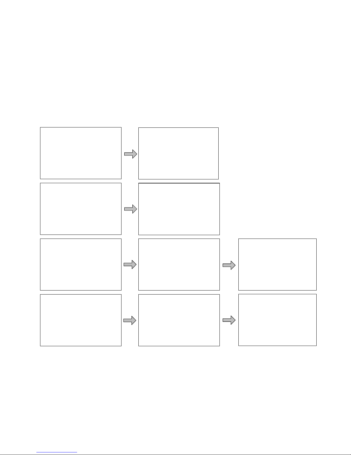
5.7 Load setting
The page of load setting could be used to set the four load working modes
of the connection solar controller (Manual, Light on/off, Light on+timer, Time
control)
√Manual Control
◎Light On/off
◎Light On+Timer
◎Time Control
Manual Control
Default : ON
◎Manual Control
√Light On/off
◎Light On+Timer
◎Time Control
Light On/Off
On 05.0V DeT 10M
Off 06.0V DeT 10M
Light On+Timer
OnTime1 01H:00M
OnTime2 01H:00M
◎Manual Control
◎Light On/off
√Light On+Timer
◎Time Control
Light On+Timer
On 05.0V DeT 10M
Off 06.0V DeT 10M
NightTime10H:00M
Time Control
□Time2
OnTime 19:00:00
OffTime 19:00:00
◎Manual Control
◎Light On/off
◎Light On+Timer
√Time Control
Time Control
■Time1
OnTime 10:00:00
OffTime 19:00:00
Page 26
22
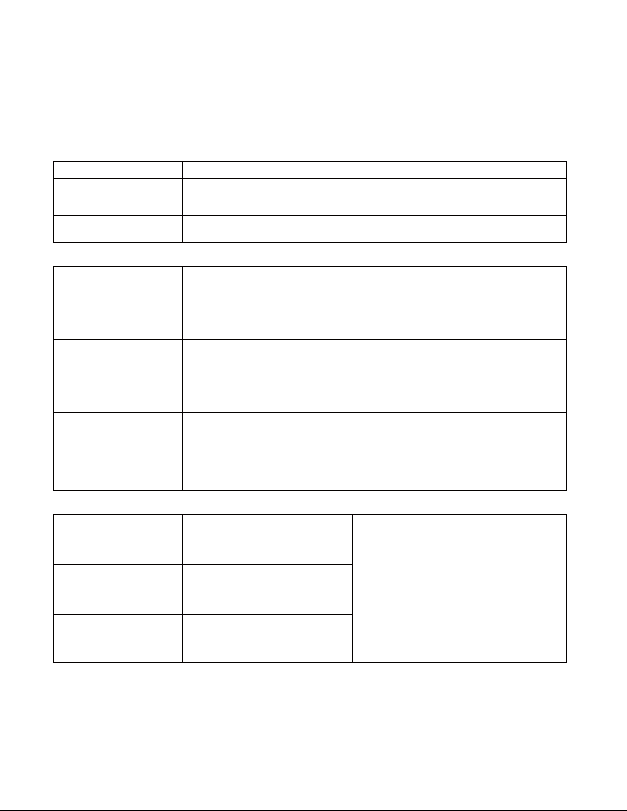
①
Manual control
Mode
Introductions
On
Load is on all the time if battery capacity is enough and
no abnormal conditions happen.
Off
Load is Off all the time.
②
Light On/Off
Light On
voltage(Night
threshold)
When input voltage of solar module is lower than Light On
voltage, it automatically turns on load output if battery
capacity is enough and no abnormal conditions happen.
Light Off
voltage(Day
threshold)
When input voltage of solar module is higher than Light Off
voltage, it automatically turns off load output.
Delay time
The confirmation time for Light signal. During the period, if
light signal voltage continues
matching Light On/Off voltage, it will
carry out corresponding actions(The time
adjustment range:0~99mins).
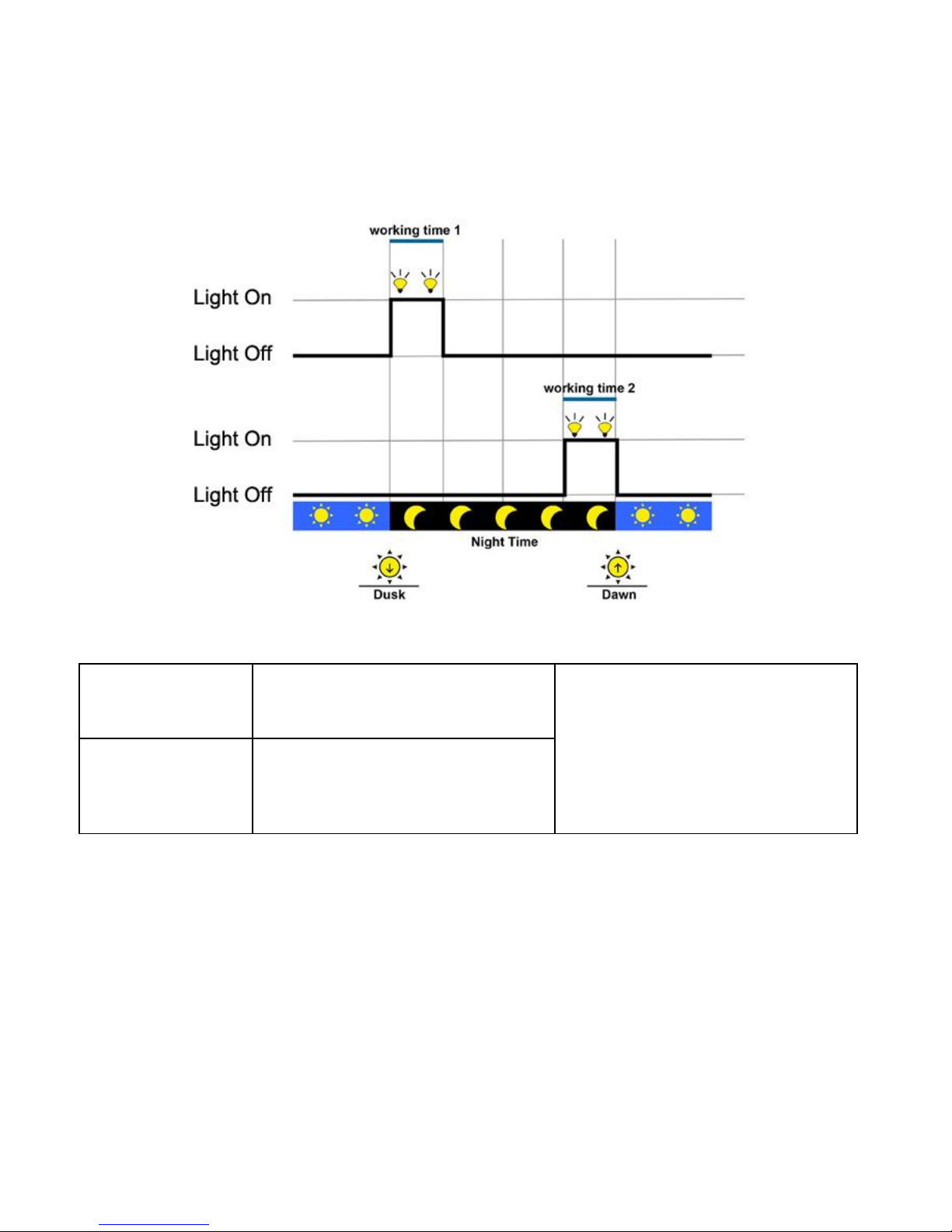
③
Light On+ timer
Working time 1
(T1)
Load working period
after light control turns
on load
Any of the working time is set
as “0”, it means this time will
stop working. The real
working time of T2 depends
on
the Night time, and the length
of T1, T2.
Working time 2
(T2)
Load working period
before light control
turns off load
Night time
Total night time
controller get from
calculation(≥3h)
Page 27
23
④Time control
Working time1
(T1)
Control on/off time of
load through real-time clock
mode.
Working time 1 is the
compulsory load working time
interval. Working time 2 is an
optional.
Working time2
(T2)
Realize the dual timer
function of the load control
through
real-time clock mode.
Page 28
24
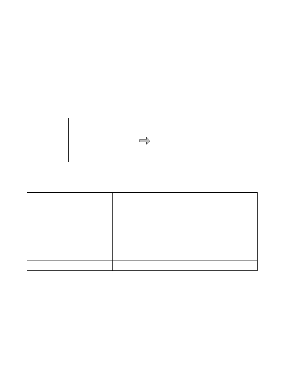
5.8 Device parameter
The software version information of solar charge controller could be checked
via the page of device parameters, and device data like device ID, device
LCD backlight time and device clock could be checked and modified. The
page of device parameter in the diagram below:
Note: the bigger the ID value of the connection device, the longer the Meter
communication identification interval (the maximum interval<6 minutes).
Type
Notes
Ver
Solar charger controller software and
hardware version numbers.
ID
Solar charger controller communication
ID numbers.
Bklight
Solar charger controller LCD backlight
working time.
Month-Day-Year H:M:S
Solar charger controller internal clock.
Device Parameter
Ver: V01.00+V02.10
ID: 001
Device Parameter
Bklight:60S
Jan-01-2013
00:01:39
Page 29

25
Factory Reset
Yes No
5.9 Device password
The password of the solar charge controller could be modified via the page
of device password; the device password is a 6-digit figure which is required
before entering the modification mode of “Control parameter”, “Load setting”,
“Device parameter”, “Device password”, “Factory reset” pages. The page of
device password in the diagram below:
Note: Solar charge controller default password is”000000”
5.10 Factory reset
The default parameter values of solar charge controller could be restored via
the Factory reset page, which means the “Control parameter”, “Load setting”,
“Charge mode” and “Device password” of the devices could be restored to
the factory defaults (the factory default password of the devices is “000000”).
Device PSW
OriPsw:xxxxxx
NewPsw:xxxxxx
Page 30
26
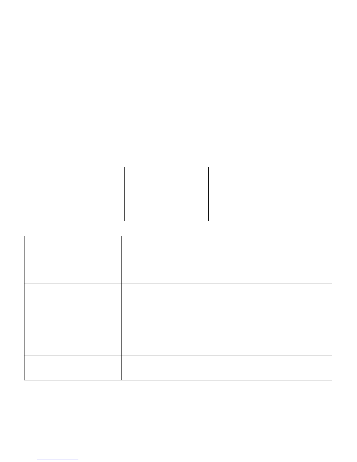
5.11 Failure information
The current failure information of the solar charge controller could be
checked via the Failure information page (a maximum of 15 failure messages
could be displayed); when the failures of solar charge controller are
eliminated, the corresponding failure information will also be automatically
eliminated.
Failure information
Details
Load MOS-Short
The MOSFET of load driver is short.
Load Circuit
The load circuit is short.
Load O. cur.
The load circuit is over current.
Input O. cur.
PV input current is over rate.
RPP Short
The MOSFET of reverse polarity protection is short.
RPP Break
The MOSFET of reverse polarity protection is break.
Char.MOS-Short
The MOSFET of charge driver is short.
Input O. Cur.
Input current is over rate.
Disc.O.O.Ctrl.
Discharge operation is out of control.
Ctrler O.Temp.
The controller is over temperature.
Comm. Timeout
The communication is timeout.
Failure Info
1.Over voltage
2.Over load
3.Short circuit
Page 31
27
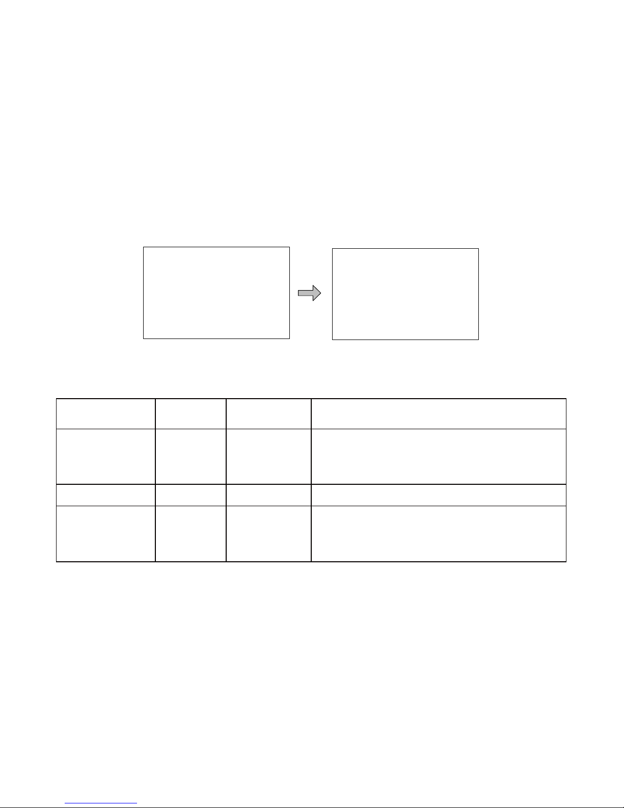
5.12 Meter parameter
The meter model, software and hardware version, and SN NO. could be
checked via Meter parameter page. And the three parameters (Switch pages,
Backlight, Audible alarm) could be browsed and modified as well.
Meter Para.
Taye: MT50
Ver: V1.00+V1.00
SN: ………………
Meter Para.
Sw-Pages:000S
Bklight:020S
AudiAlam: OFF
Note: When the set up is accomplished, the auto switch page cannot
become effective until ten minutes later.
Parameters
Default
Range
Remark
Sw-Pages
0
0~120S
The automatic switchover
inverter for real-time
monitoring page
BKlight
20
0~999S
LCD backlight time
AudiAlam
OFF
ON/OFF
Turn ON /OFF the acoustic alarm
function in case of failure on solar
charge controller
Page 32
28
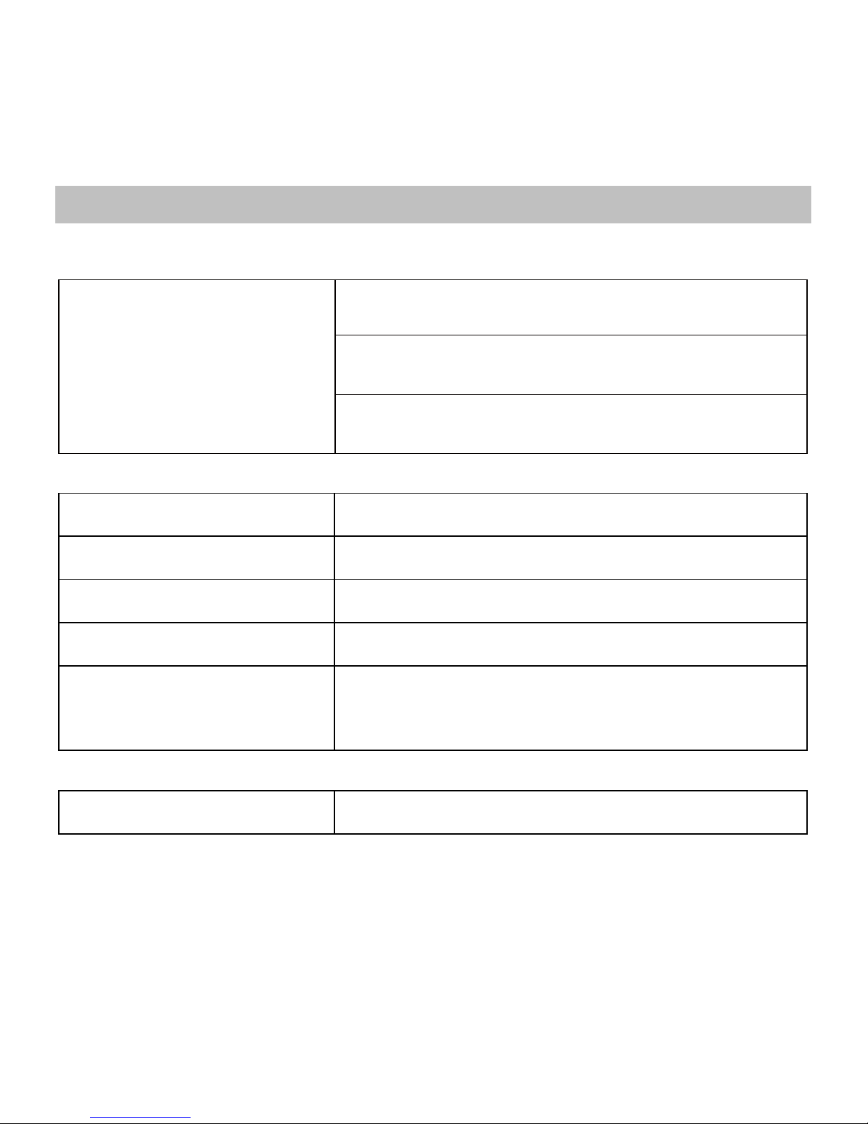
6 Technical Specifications
Electrical Parameter
Self-consumption
Backlight and acoustic alarm ON<65mA
Backlight ON<23mA
Backlight OFF<15mA
Mechanical Parameter
Faceplate dimensions
98×98 mm
Frame dimensions
114×114 mm
Connector type
RJ45
Meter cable
Standard 2m,Max 50 m
Meter weight
Simple package: 0.23 Kg
Standard package:0.32 Kg
Environmental Parameter
Ambient temperature
-20℃~+70℃
Page 33
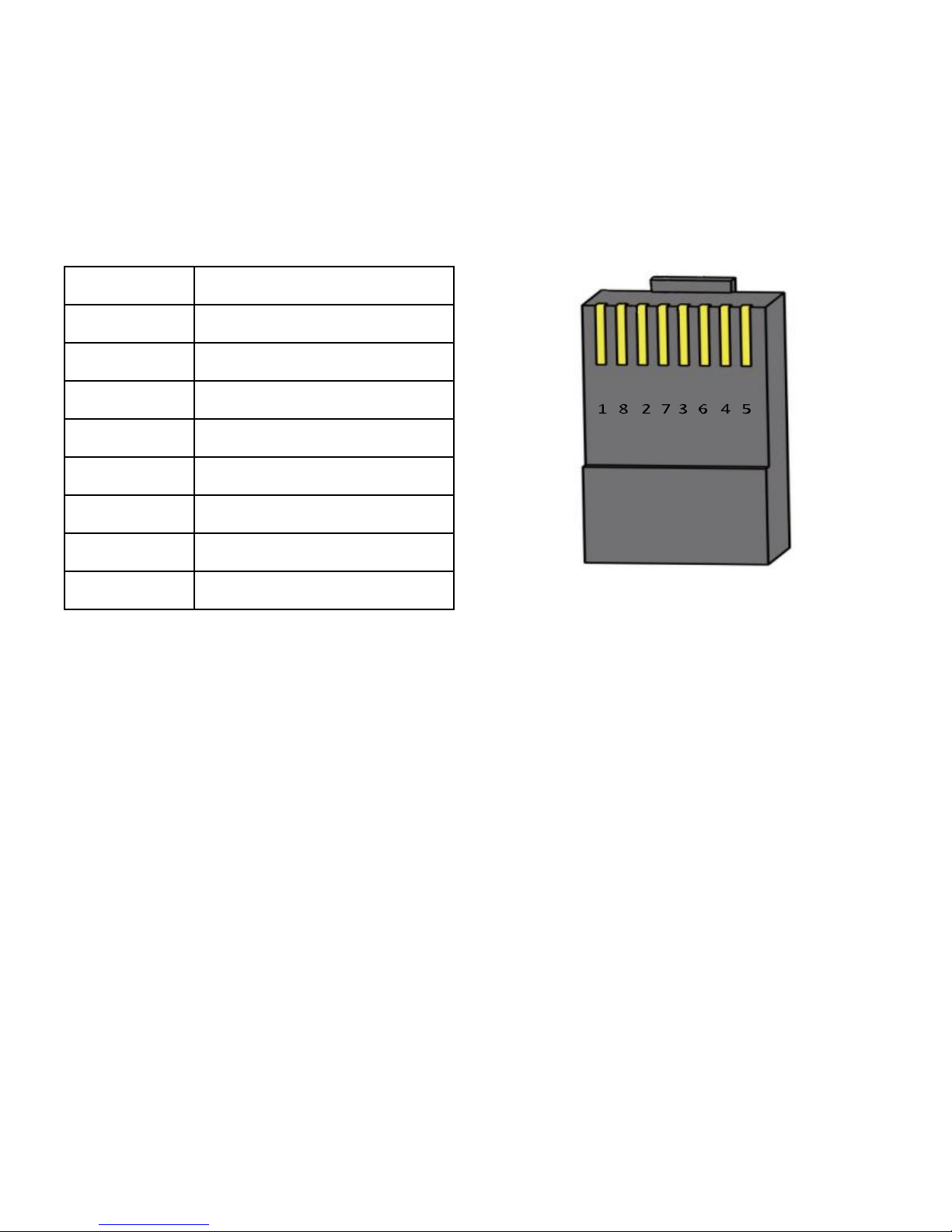
29
Definitions of interface pins
Pin No.
Definition
1
Power+5~12V input
2
Power+5~12V input
3
RS485-B
4
RS485-B
5
RS485-A
6
RS485-A
7
GND
8
GND
Data cable pin definitions
Page 34
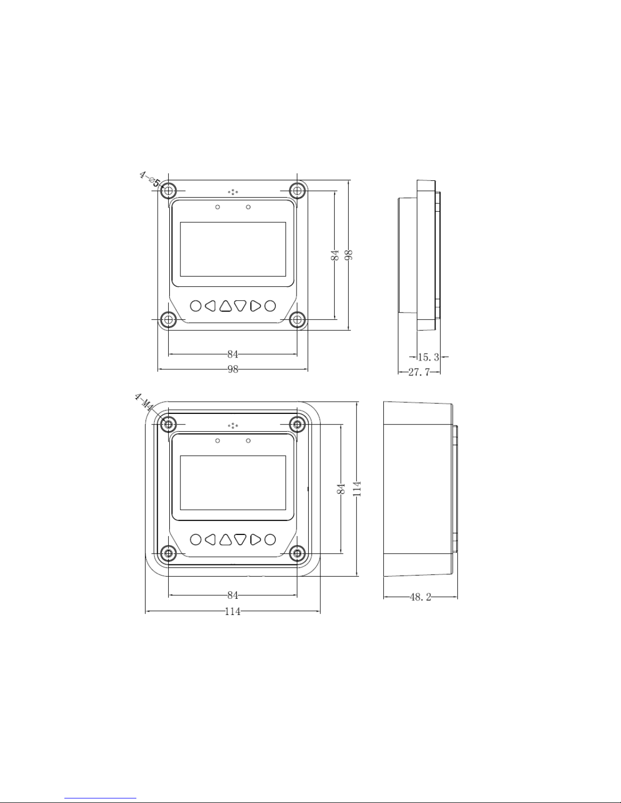
30
REMOTE METER DIMENSIONS (mm)
Any changes without prior notice! Version number:V2.1
Page 35

Page 36

BEIJING EPSOLAR TECHNOLOGY CO.,LTD.
Te l : +86-10-82894112 / 82894962
Fax: +86-10-82894882
E-mail: [email protected]
Website: http://www.epever.com/
 Loading...