

Page 1

LS1024BP/ LS2024BP
——Solar Charge Controller
Thank you very much for selecting our product!
This manual offers important information and
suggestions with respect to installation, use and
troubleshooting, etc. Please read this manual carefully
before using the product and pay attention to the
safety recommendations in it.
EPSOLAR
USER MANUAL
Page 2

Page 3
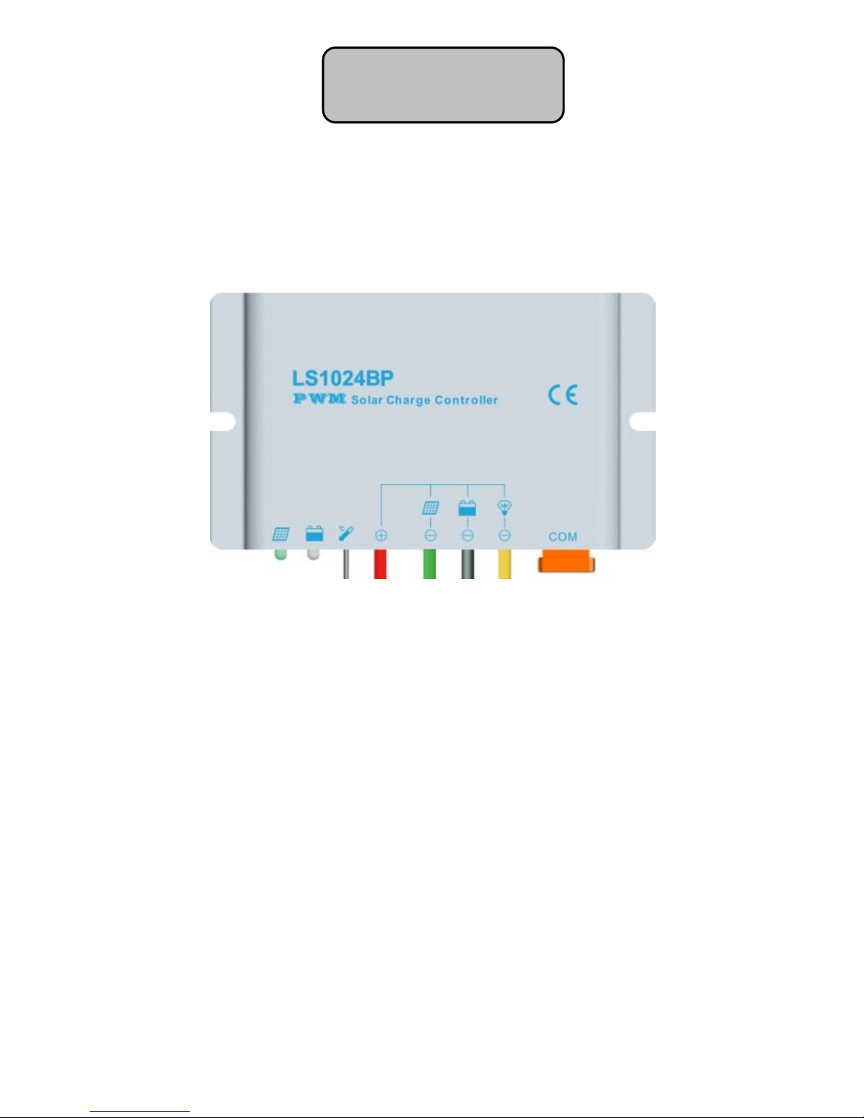
LS1024BP/ LS2024BP
——Solar Charge Controller
Nominal system voltage 12 / 24VDC*
Maximum PV input voltage 50V
Nominal charge / discharge current
LS1024BP 10A
LS2024BP 20A
*The solar charge controller has the system voltage 12/24V automatic
recognition function and custom define function, and all charge,
discharge and load control parameters can be modified.
Warranty: The charge controller is warranted to be free from defects
for a period of two years from the date of shipment to the original end
user.
Notice: Manufacture is not responsible for the damage of any
part of controller due to operator's misuse, battery parameters
mismatch, unreasonable system configuration, unauthorized
repairment or exceeding the specified parameter.
LandStar
Page 4

Page 5

Contents
1 Important Safety Information ..................................1
2 General Information ................................................1
3 Installation Instructions ...........................................2
3.1 General Installation Notes ........................2
3.2 Wiring ..........................................................3
4 Operation ..................................................................4
4.1 LED Indicators ...........................................4
4.2 Setting Operation ......................................5
5 Protection, Troubleshooting ...................................6
5.1 Protection ...................................................6
5.2 Troubleshooting .........................................7
6Technical Specifications ..........................................9
Page 6

1
1 Important Safety Information
Please inspect the controller thoroughly after it is delivered. If any
damage is seen, please notify the shipping company or our company
immediately.
2 General Information
LandStar BP series solar charge controller adopts the most advanced
digital technique and operates fully automatically. It’s Ideal for extreme
environments with corrosion, dust, water etc and has various unique
functions:
12V/24V automatic identify or user-defined working voltage.
High efficient Series PWM charging, increase the battery lifetime and
improve the solar system performance.
Use MOSFET as electronic switch, without any mechanical switch.
Multiple load control modes, increase the flexibility of the load output
Gel, Sealed, Flooded and user-defined battery type option.
Adopt temperature compensation, correct the charging and
discharging parameters automatically and improve the battery
lifetime.
New SOC method of calculating accurately displays the available
battery capacity.
LandStar BP has no keys , The control function and the switch
condition of the load can be modified by communication connection.
Electronic protection: Overheating, over charging, over discharging,
overload, and short circuit.
Reverse protection: any combination of solar module and battery.
With functions of current power calculation and real-time energy
statistics recording, it is convenient for users to view charging and
discharging energy of each day, month, year and total value.
Use of standard Modbus communication protocol for TTL-232 bus
connections, communication protocol compatibility much better
Support firmware upgrade
Page 7

2
Fully encapsulated PCB, IP67 protection
Aluminumhousing
3 Installation Instructions
3.1 General Installation Notes
Be very careful when working with batteries. Wear eye protection.
Have fresh water available to wash and clean any contact with
battery acid.
Never short circuit the battery positive and negative terminals and
wires which may cause explosion or fire.
Install external fuses/breakers as required.
Disconnect the solar module and fuse/breakers near to battery
before installing or adjusting the controller.
Confirm that power connections are tightened to avoid excessive
heating from loose connection.
Uses insulated tools and avoid placing metal objects near the
batteries.
Explosive gasses may be present during charging. Be certain there is
sufficient ventilation to release the gasses.
Loose power connections and/or corroded wires may result in
resistive connections that melt wire insulation, burn surrounding
materials, or even cause fire. Ensure tight connections and use
cable clamps to secure cables and prevent them from swaying in
mobile applications.
Only charge the batteries that comply with the parameters of
controller.
Battery connection may be wired to one battery or a bank of batteries.
The following instructions refer to a singular battery, but it is implied
that the battery connection can be made to either one battery or a
group of batteries in a battery bank.
Page 8

3
3.2 Wiring
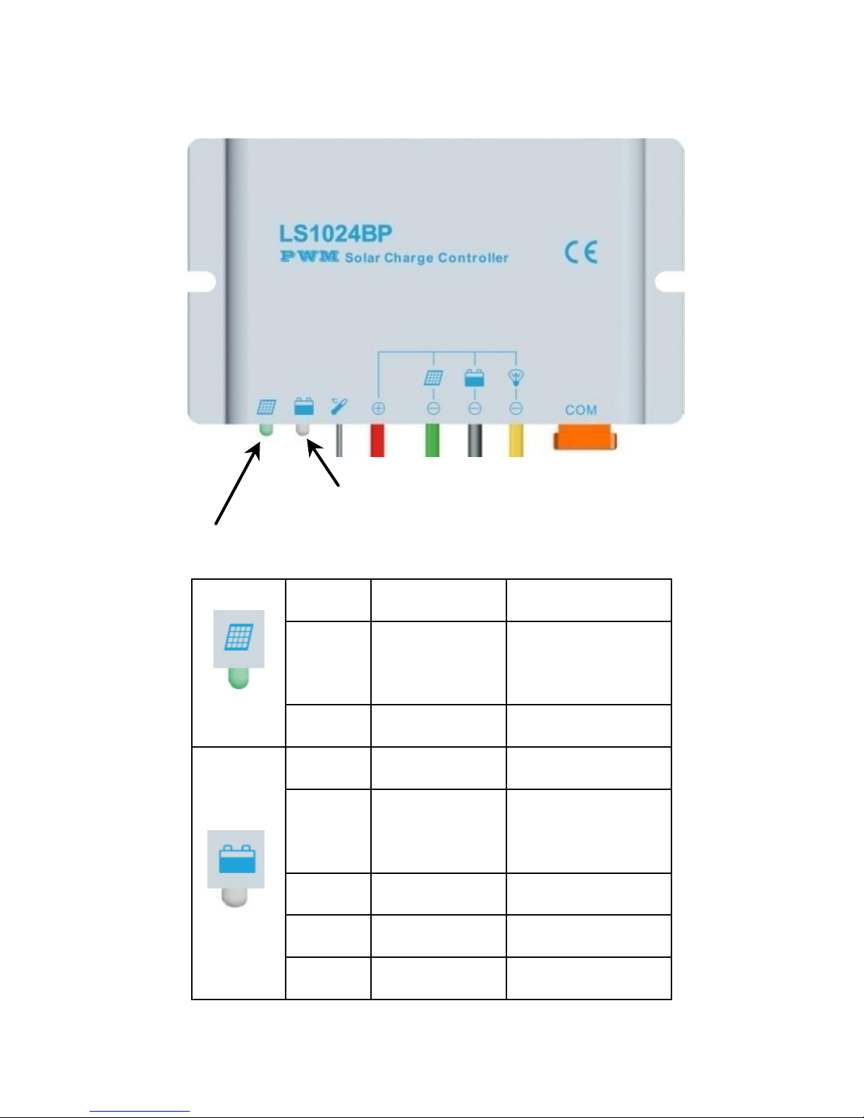
1. Connect components to the charge controller in the sequence as
shown above picture and pay much attention to the “+”(Red)and
“-“(Black).Always power the battery First.
2. After power the battery, check the battery indicator on the controller,
it will be green. If it’s not green, please refer to chapter 5.
3. The battery fuse should be installed as close to battery as possible.
The suggested distance is within 150mm.
Page 9
4
4 Operation
4.1LED Indicators
Battery Status LED indicator
Charging Status LED indicator
Indicator Status Description
Green
On Solid
Normal
Green
Slowly
Flashing
In charging
Green
OFF
No charge
Green
On Solid
Normal
Green
Slowly
Flashing
Full
Green
Fast Flashing
Over voltage
Orange
On Solid
Under voltage
Red
On Solid
Over discharged
Page 10
5
Red
Flashing
Battery over
temperature
Charging and battery indicator
(red)flashing simultaneously
System voltage
error
Charging and battery
indicator(orange)flashing
simultaneously
Controller
overheating
4.2Setting Operation
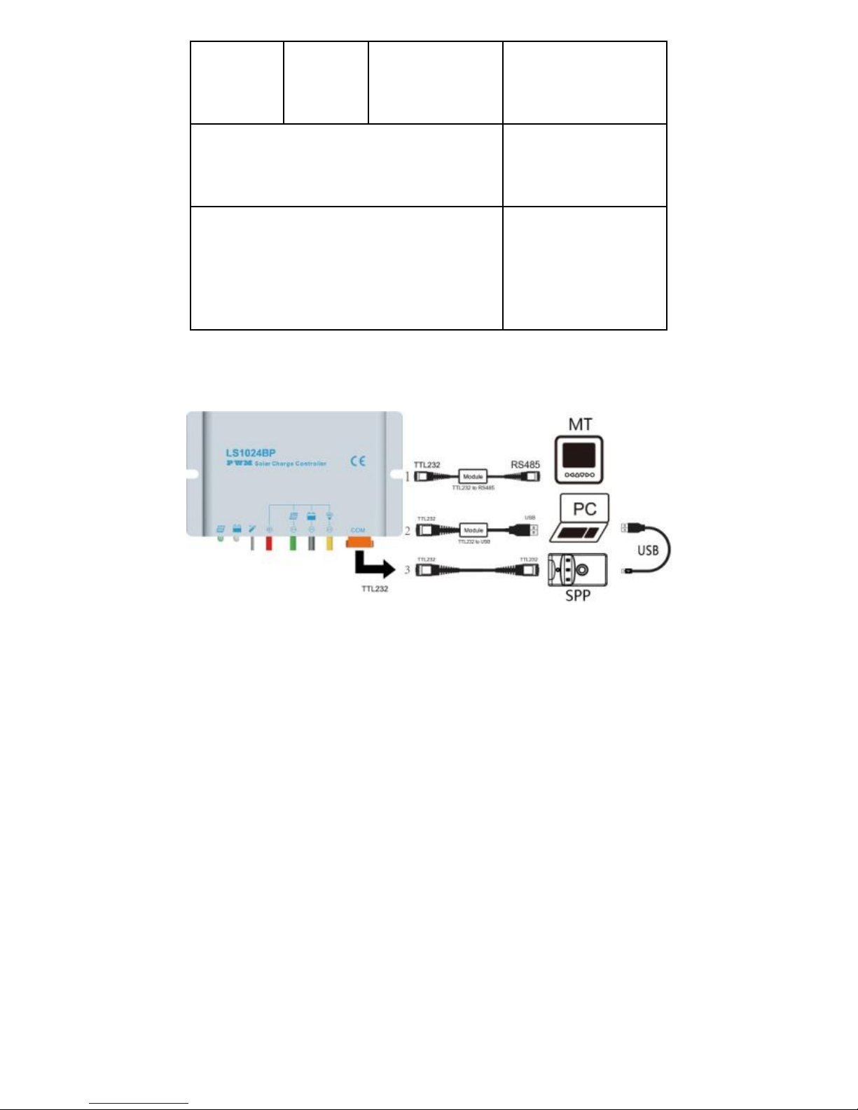
Three methods to program the controller:
1–Remote Meter,MT50/MT100(Use dedicated TTL232 to RS485
communication cable with CC-TTL-RS485-200U).
2–Super Parameter Programmer, SPP-01(Use dedicated TTL232 to
TTL232 communication cable with CC-TTL-TTL-150U).
This method can realize one-key setting operation which is suitable for
bulk quantity products setting or applied in the projects.
3–PC monitoring setting software “Solar Station Monitor” ( Use
dedicated TTL232 to USB communication cable with
CC-USB-TTL-150U).
Through the remote meter and PC software, it can realize real-time
monitoring, modification of control parameter, charge mode, load work
mode, inquiry of failure information etc.
Page 11

6
Note: Please refer to the user manual of MT, SPP-01 and PC
software for more details.
·Load Set
1.Manual Control
2.Light ON/Off (default)
3.Light ON+ Timer
4.Time Control
·Battery Type
1.Gel 2.Sealed(default) 3.Flooded 4.User
5 Protection, Troubleshooting
5.1 Protection
·PV Array Short Circuit
If PV array short circuit occurs, clear it to resume normal charge
automatically.
·Load Overload
If the load current exceeds the rated discharge current of controller
(≥1.05 times rated discharge current), the controller will disconnect
the load. Once the overload occurs, the way to solve is to send a
“remote load switch” command or reset the controller after reducing
the load.
·Load Short Circuit
Fully protected against load wiring short-circuit(≥2 times rated
discharge current). After one automatic load reconnect attempt, the
fault must be cleared by restarting the controller or sending a “remote
load switch” command.
·PV Reverse Polarity
Fully protection against PV reverse polarity, no damage to the
controller will result. Correct the miswire to resume normal operation.
·Battery Reverse Polarity
Fully protection against battery reverse polarity, no damage to the
controller will result. Correct the miswire to resume normal operation.
Page 12

7
·Battery working voltage error
If battery voltage does not match controller working voltage, controller
will stop working. After correcting the voltage, the fault must be
cleared by restarting the controller or sending a “remote load switch”
command.
·Damaged Temperature Sensor
If the temperature sensor short-circuited or damaged, the controller
will be charging or discharging at the default temperature 25℃ to
prevent the battery damaged from overcharging or over discharged.
·Overheating Protection
If the temperature of the controller heat sink exceeds 85C, the
controller will automatically start the overheating protection and stop
the charging and discharging. When the temperature is below 75℃, the
controller will resume to work.
·High Voltage Transients
PV is protected against smaller high voltage surge. In lightning prone
areas, additional external suppression is recommended.
Note: The controller has daily automatic fault recovery function
which will reduce the manual operation and can intelligently
eliminate the fault caused by non-actual hardware failure.
5.2 Troubleshooting
Faults
Possible
reasons
Troubleshooting
Charging LED
indicator off
during daytime
when sunshine
falls on PV
modules
properly.
PV
array
disconnection
Check that PV and battery wire
connections are correct and tight.
Page 13

8
Green Battery
LED indicator
fast flashing
Battery voltage
higher than over
voltage
disconnect
voltage(OVD)
Check the battery voltage. If it
over high, disconnect the solar
module immediately and change
a new controller.
Battery
LED indicators
orange
Battery under
voltage
Load output is normal. Charging
LED indicator will return to green
automatically when fully charged.
Battery LED
indicators RED
color and loads
not working.
Battery
over discharged
The controller cut off the output
automatically. LED indicator will
return to green automatically
when fully charged.
Load abnormal
shutdown
Over load
Remove or cut out the additional
load and sending a “remote load
switch” command , the
controller will resume to work
after 3s or restart the controller.
Load abnormal
shutdown
Short circuit
Clear short circuit and sending a
“remote load switch” command,
the controller will resume to work
after 3s or restart the controller.
All the led
indicator
flashing
(battery orange
indicator
flashing)
Too high
temperature of
controller
When heat sink of the controller
exceeds 85 ℃, the controller will
automatically cut input and
output circuit. When the
temperature below 75℃, the
controller will resume to work.
Please reduce the environment
temperature, the power of solar
module or the power of the load.
All the led
indicator
flashing
(battery red
indicator
flashing)
System voltage
error
Check whether the battery
voltage match with the controller
working voltage. Please change
to a suitable battery or reset the
working voltage.
Page 14

9
SOC value
incorrect
Choose the
wrong battery
type; Using the
reconfigured
profile of the
user defined
battery type.
Correct the right battery type;
Using the configuration of the
charging voltage compensation if
choosing the user defined battery
type and ignore the SOC
6Technical Specifications
Electrical Parameters
Description
Parameter
Nominal System Voltage
12 /24VDC
Max. PV input voltage
50V
Max. Battery Terminal Voltage
34V
Rated Battery Current
LS1024BP10A
LS2024BP20A
Charge Circuit Voltage Drop
≤0.28V
Discharge Circuit Voltage Drop
≤0.20V
Self-consumption
≤8.4mA/12V
≤7.8mA/24V
Temperature compensation coefficient
-3mV/℃/2V (Default)
Grounding
Positive grounding
Page 15

10
Battery Voltage Parameters (parameters is in 12V system at 25℃, please
use X 2 in 24V system)
Control Parameters
Battery charging
setting
Gel
Sealed
Flooded
User
Over Voltage
Disconnect Voltage
16.0V
16.0V
16.0V
9~17V
Charging Limit
Voltage
15.0V
15.0V
15.0V
9~17V
Over Voltage
Reconnect Voltage
15.0V
15.0V;
15.0V
9~17V
Equalize Charging
Voltage
——
14.6V
14.8V
9~17V
Boost Charging
Voltage
14.2V;
14.4V
14.6V
9~17V
Float Charging
Voltage
13.8V;
13.8V;
13.8V
9~17V
Boost Reconnect
Charging Voltage
13.2V;
13.2V
13.2V
9~17V
Low Voltage
Reconnect Voltage
12.6V
12.6V
12.6V
9~17V
Under Voltage
Warning Reconnect
Voltage
12.2V
12.2V
12.2V
9~17V
Under Voltage
Warning Voltage
12.0V
12.0V
12.0V
9~17V
Low Voltage
Disconnect Voltage
11.1V
11.1V
11.1V
9~17V
Discharging Limit
Voltage
10.6V
10.6V
10.6V
9~17V
Equalize Duration
——
2 hrs.
2 hrs.
0~3 hrs.
Boost Duration
2 hrs.
2 hrs.
2 hrs.
0~3 hrs.
Page 16
11
Notes:
1.The default battery type is Sealed. For Gel, Sealed, Flooded
battery type, the voltage point is fixed, unable to modify it.
2.User type is the user defined battery type. The default value is
the same as sealed type. When modify it, please follow the below
logistic relation:
a ) Over Voltage Disconnect Voltage>Charging Limit Voltage≥
Equalize Charging Voltage ≥Boost Charging Voltage≥Float
Charging Voltage >Boost Reconnect Charging Voltage;
b ) Over Voltage Disconnect Voltage>Over Voltage Reconnect
Voltage ;
c) Low Voltage Reconnect Voltage>Low Voltage Disconnect Voltage
≥Discharging Limit Voltage;
d ) Under Voltage Warning Reconnect Voltage>Under Voltage
Warning Voltage≥Discharging Limit Voltage;
e ) Boost Reconnect Charging voltage>Low Voltage Disconnect
Voltage.
*Please carefully to select battery type. It will damage battery if
the setting is incorrect.
Environmental parameters
Environmental parameters
Parameter
Working temperature
-30℃ to +55℃
Storage temperature
-30℃to +80℃
Humidity
≤95% NC
Enclosure
IP67
Page 17
12
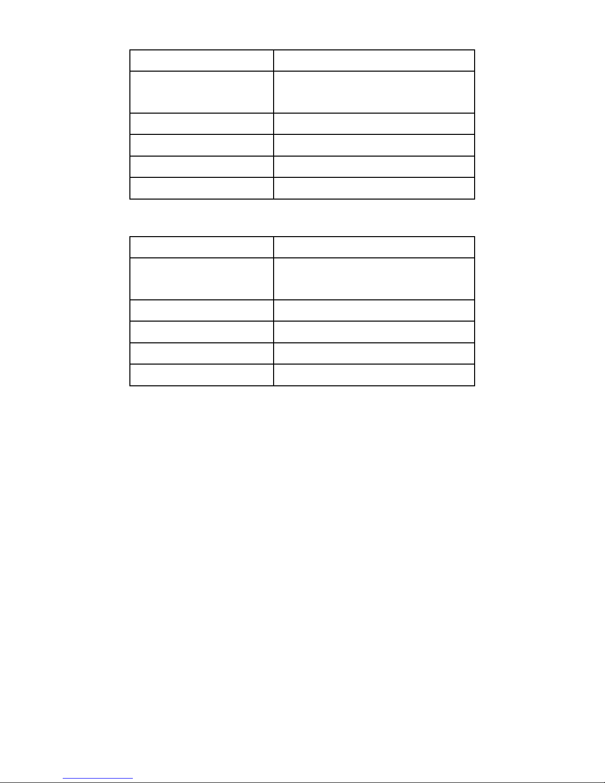
LS1024BPMechanical parameters
Mechanical Parameter
Parameter
Overall dimension
108.5(4.27)x64.5(2.54)x25.6(1.01)
mm/inches
Mounting dimension
100.5(3.96) mm/inches
Mounting hole size
Φ4.5
Power cable
4mm2
Net weight
0.4kg
LS2024BP Mechanical parameters
Mechanical Parameter
Parameter
Overall dimension
139(5.47)x76.5(3.01)x28(1.10)
mm/inches
Mounting dimension
131(5.16) mm/inches
Mounting hole size
Φ4.5
Power cable
6mm2
Net weight
0.6kg
Page 18

Final interpretation right of the manual belongs to our company.
Any changes without prior notice!
Ver1.4
 Loading...