

Epsolar eTracer ET4415BND, eTracer ET6415BND, IT3415ND, IT4415ND, IT6415ND Operation Manual
Page 1

eTracer-BND Series
—— Maximum Power Point Tracking
Solar Charge Controller
Thank you very much for selecting our product!
This manual offers important information and suggestion about installation, use and
troubleshooting, etc. Please read this manual carefully before using the product and pay
attention to the safety recommendations in it.
EPsolar
OPERATION
MANUAL
Page 2

Page 3
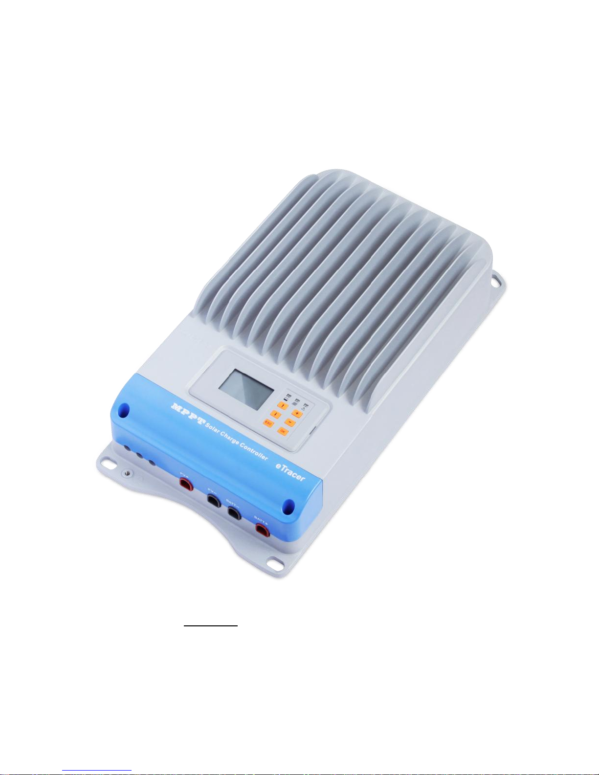
eTracer-BND Series
—— Maximum Power Point Tracking
Solar Charge Controller
Models:
ET4415BND/ET6415BND
Final interpretation right of the manual belongs to EPsolar.
Any changes without prior notice!
Page 4

Contents
1 Important Safety Information ..................................................................................... 1
2 General Information ................................ ................................ ................................... 2
2.1 Overview ......................................................................................................... 2
2.2 Models & Parameters ...................................................................................... 3
2.3 Characteristics ................................................................................................. 4
2.4 Accessories ..................................................................................................... 6
3 Installation Instructions .............................................................................................. 7
3.1 General Installation Notes ............................................................................... 7
3.2 Mounting ......................................................................................................... 8
3.3 Wiring ................................................................ ................................ ............. 9
4 Operation ................................................................................................................. 13
4.1 MPPT Technology ........................................................................................ 13
4.2 Battery Charging Information ....................................................................... 15
4.3 LED Indication .............................................................................................. 17
4.4 LCD Display & Operation ............................................................................ 18
5 Protections, Troubleshooting & Maintenance .......................................................... 25
5.1 Protections..................................................................................................... 25
5.2 Troubleshooting ............................................................................................ 25
5.3 Maintenance .................................................................................................. 26
6 PC Software ................................................................................................ ............. 28
7 Warranty .................................................................................................................. 30
8 Specifications ........................................................................................................... 31
9 Conversion Efficiency Curves ................................................................................. 33
10 Dimensions ............................................................................................................ 37
Page 5
1
1 Important Safety Information
This manual contains important safety, installation and operating instructions for the
eTracer-BND Series MPPT solar controller. Save these instructions.
The following symbols are used throughout this manual to indicate potentially
dangerous conditions or mark important safety instructions.
WARNING: Indicates a potentially dangerous condition. Use
extreme caution when performing this task.
CAUTION: Indicates a critical procedure for safe and proper
operation of the controller.
NOTE: Indicates a procedure or function that is important for
safe and proper operation of the controller.
General Safety Information
Read all of the instructions and cautions in the manual before installation.
There are no user serviceable parts inside the controller. Do not disassemble or
attempt to repair the controller.
Mount the controller indoors. Prevent exposure to the elements and do not allow
water to enter the controller.
Install eTracer-BND controller in well ventilated places, the heat sink of controller
may become very hot during operation.
Install external fuses/breakers as required.
Disconnect the solar module and fuse/breakers near to battery before installing or
adjusting the controller.
Power connections must remain tight to avoid excessive heating from a loose
connection.
Page 6

2
2 General Information
2.1 Overview
Thank you for selecting the eTracer-BND Series MPPT solar controller. The controller
is a high-end industrial class product based on multiphase synchronous rectification
technology and has the features of high efficiency and reliability. The features are listed
below:
12/24/36/48VDC system voltage automatic recognition or user-defined working
voltage
Smart tracking algorithm that finds and maintains operation at the solar array peak
power point with the tracking efficiency as high as 99.7%
Multiphase synchronous rectification technology ensures peak conversion efficiency
is up to 98.7%
High effective conversion efficiency at small power charging with multiphase power
decentralized control and improves the generated energy
Double processors architecture with high speed and performance improves the
response speed and optimizes the performance of the system
Multiphase control technology, optimizes charging current smoothness, reduces
ripple and improves the system generating efficiency
Excellent EMC design
Excellent heat dissipation. Using the integration of cast aluminum radiator shell, the
controller can be natural cooling
128*64 dot-matrix LCD intuitively displays data and state, 6 buttons combinations
for easy operation
RS-232, RS-485 ports via the open standard Modbus protocol are supported to
meet different occasion of demand
Support 4 charging preprogram options: Sealed, Gel, Flooded and User-defined
Protection: Over temperature, over charging, PV (battery) revered, PV reverse
current protect at night, over current protection
Actual Power Display and record function make convenience to check the datum
every day, every month and every year
Log function: work logs and alarm logs are all recorded
Firmware update: convenience to after-service and maintenance service
The controller features a built-in fuzzy control algorithm that maximizes the energy
from the solar module(s) and charge the battery.
Page 7

3
The battery charging process has been optimized for long battery life and improved
system performance. The comprehensive self-diagnostics and electronic protection
functions can prevent damage from installation mistakes or system faults.
Please take the time to read this operation's manual and become familiar with the
controller. This will help you make full use of all the functions and improve your PV
system.
2.2 Models & Parameters
Maximum 150 Volt dc systems**
RS-232, RS-485 port
ET4415BND
Rated charge current 45A
PV input Max. Power 2400W
12V/24V/36V/48V system voltage and auto work *
ET6415BND
Rated charge current 60A
PV input Max. Power 3200W
12V/24V/36V/48V system voltage and auto work *
* The “auto work” setting allows the controller to detect the system voltage
automatically on start up.
** Array voltage should never exceed maximum PV input voltage. Refer to the
solar module documentation to determine the highest expected array Voc (open
circuit voltage) as defined by the lowest expected ambient temperature for the
system location.
Page 8
4
2.3 Characteristics
2
3 4 5
6
1
8 7 14
13
16
15
12
11
10
9
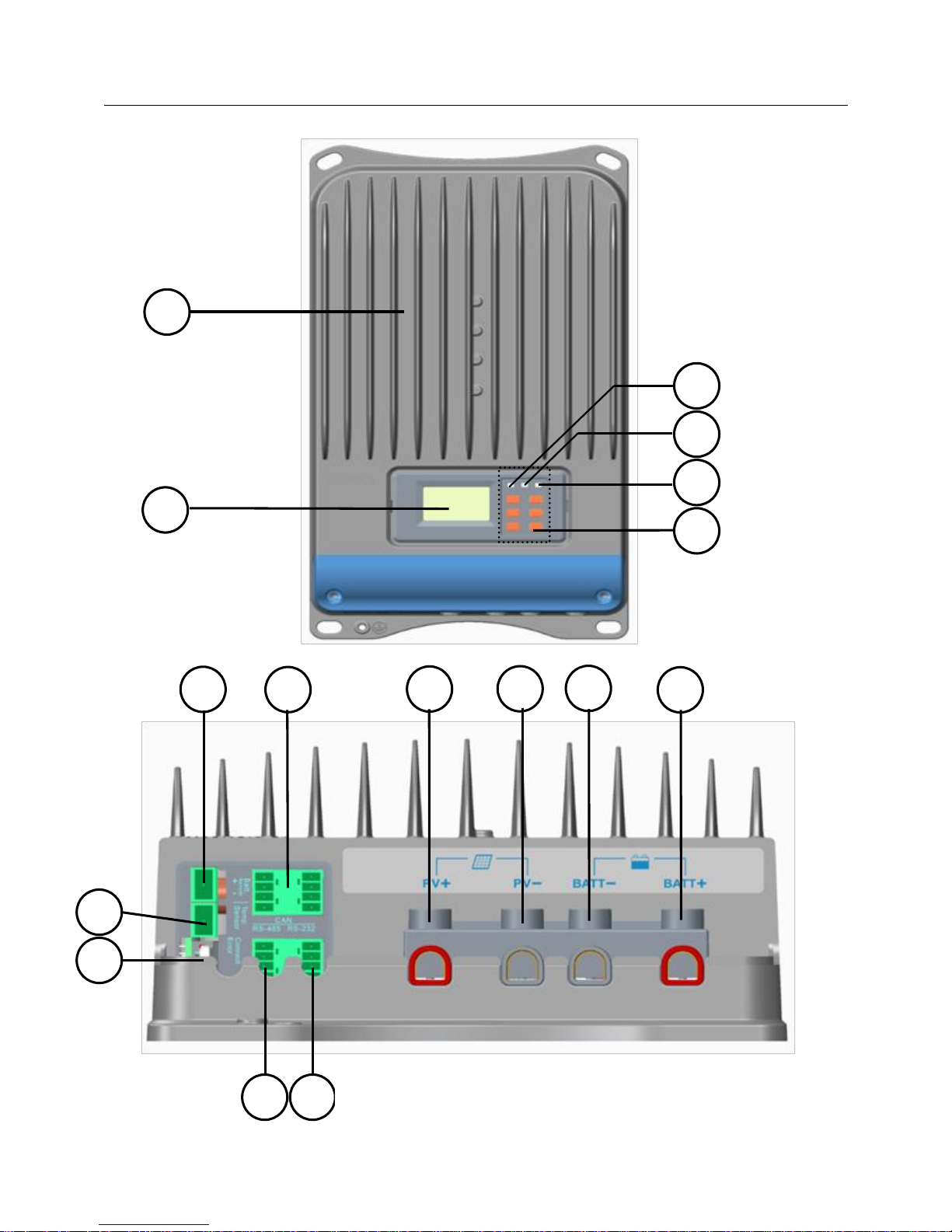
Figure 2-1 eTracer-BND features
Page 9

5
1 – Heat Sink
Aluminum heat sink to dissipate controller heat.
2 – LCD
Display the status and data.
3 – Battery LED indicator
Three states of battery LED indicator show charging status.
4 – Charging LED indicator
Indicate that the battery is charging or not.
5 – Fault LED indicator
Indicate that controller faults.
6 – Buttons
Browse or modify all parameters.
7 – RS-232 port
Monitor controller by PC and update controller software.
8 – RS-485 port
Monitor controller by PC and update controller software.
9 –RTC battery
Power to RTC, battery model is CR2032.
10 – Remote Temperature Sensor port(MC1.5-5.08-2L)
Connection for a RTS (Remote Temperature Sensor, optional) to remotely
monitor battery temperature.
11 – Remote Battery Voltage Sensor port(MC1.5-5.08-2L)
Connection for RBVS (Remote Battery Voltage Sensor) to provide accurate
battery voltage measurement.
12 – Reserved Port (MC1.5-3.81-4L)
Reserved port for future development.
13 – Solar Positive Terminal
Power connection for Solar Positive Terminal.
14 –Solar Negative Terminal
Page 10

6
Power connection for Solar Negative Terminal.
15 –Battery Negative Terminal
Power connection for Battery Negative Terminal.
16 –Battery Positive Terminal
Power connection for Battery Positive Terminal.
2.4 Accessories
Remote Temperature Sensor (Model:RTS300R10K5.08A)
Acquiring of battery temperature for undertaking temperature compensation of control
parameters, the standard length of the cable is 3m (length can be customized). The
RTS300R10K5.08A connects to the MC1.5-5.08-2L port (10th ) on the controller.
USB To RS-485 Converter(Model:CC-USB-RS485-150U-3.81)
The USB to RS-485 converter is used to monitor each controller on the network using
EPsolar Station PC software and update the firmware. The length of cable is 1.5m. The
CC-USB-RS485-150U-3.81 connects to the MC1.5-5.08-2L port (8th ) on the
controller.
Page 11

7
3 Installation Instructions
3.1 General Installation Notes
Read through the entire installation section first before beginning installation.
Be very careful when working with batteries. Wear eye protection. Have fresh water
available to wash and clean any contact with battery acid.
Use insulated tools and avoids placing metal objects near the batteries.
Explosive battery gases may be present during charging. So well ventilation of
battery box is recommended.
Avoid direct sunlight and do not install in locations where water can enter the
controller.
Ventilation is highly recommended if mounted in an enclosure. Never install the
eTracer-BND in a sealed enclosure with flooded batteries! Battery fumes from
vented batteries will corrode and destroy the eTracer-BND circuits.
Loose power connections and/or corroded wires may result in resistive connections
that melt wire insulation, burn surrounding materials, or even cause fire. Ensure tight
connections and use cable clamps to secure cables and prevent them from swaying in
mobile applications.
Gel, Sealed or Flooded batteries are recommended, other kinds please refer to the
battery manufacturer.
Battery connection may be wired to one battery or a bank of batteries. The following
instructions refer to a singular battery, but it is implied that the battery connection
can be made to either one battery or a group of batteries in a battery bank.
Multiple same models of controllers can be installed in parallel on the same battery
bank to achieve higher charging current. Each controller must have its own solar
module(s).
Select the system cables according to 3.5A/mm2 or less current density.
Page 12
8
3.2 Mounting
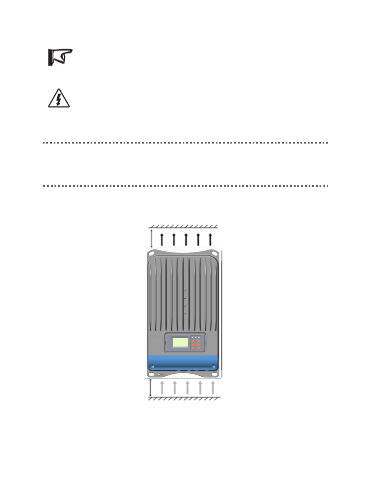
NOTE: The eTracer-BND controller requires at least 150mm of clearance
above and below for proper air flow. Ventilation is highly recommended if
mounted in an enclosure.
WARNING: Risk of explosion! Never install the eTracer-BND in a sealed
enclose with flooded batteries! Do not install in a confined area where
battery gas can accumulate.
Step1: Choose a Mounting Location
Place the eTracer-BND controller on a vertical surface protected from direct sunlight,
high temperatures, and water.
Step2: Check for Clearance
Place the eTracer-BND in the location where it will be mounted. Verify sufficient room
to run wires and sufficient room above and below the controller for air flow.
Figure3-1 Required mounting clearance for air
COOL AIR
WARM AIR
AT LEAST
150mm
AT LEAST
150mm
Page 13
9
Step3: Mark Holes
Mark the four (4) mounting holes locations on the mounting surface.
Step 4: Drill Holes
Remove the controller and drill four sizeable holes at the marked locations.
Step 5: Secure the Controller
Place the controller on the surface and align the mounting holes with the drilled holes in
step 4. Secure the controller in place using the mounting screws.
3.3 Wiring
NOTE: A recommended connection order has been provided for maximum
safety during installation.
NOTE: Do not entangle all wiring together. Communication cable and
power wires should be as far as possible to avoid interfering
communication signal transmission.
NOTE: The eTracer-BND is a negative ground controller. Any negative
connection of solar or battery can be earth grounded as required.
CAUTION: For mobile applications, be very certain that all wirings are
connected securely. Use cable clamps to prevent cables from swaying when
the vehicle is in motion. Unsecured cables create loose and resistive
connections which may lead to excessive heating and/or fire.
Step 1: Remote Temperature Sensor Connection (RTS300R10K5.08A)
CAUTION: The controller will perform temperature compensation for
charging parameters according to the device temperature.
CAUTION: Equipment Damage! Never place the temperature sensor
inside a battery. Both the RTS300R10K5.08A and the battery will be
damaged.
The included remote temperature sensor RTS300R10K5.08A is recommended for
effective temperature compensated charging. Connect the RTS300R10K5.08A to
the10th port (MC1.5-5.08-2L) on the controller (see figure 2-1). The cable standard
length is 3 meters and could be customized. There is no polarity, so either wire (+ or -)
Page 14

10
can be connected to either screw terminal. No damage will result if connect the
RTS300R10K5.08A to the remote battery voltage sense port, but the connection will
not be recognized.
Step 2: Remote Battery Voltage Sensor Connection
NOTE: When connecting Remote Battery Voltage Sensor, please pay
attention to ‗+‘ and ‗-‘ (see figure 2-1).
CAUTION: Be careful when installation. Please never plug the voltage
sensor wires into to the RTS300R10K5.08A terminals (10th Port). This will
cause an alarm or damage the controller.
The voltage at the battery terminals on the controller may differ slightly from the real
battery voltage due to connection and cable resistance. The remote battery voltage
sensor will enable the controller to detect the battery voltage more exactly and avoid
voltage deviation. The battery voltage sensor connection is not required to operate the
controller, but it is recommended for the best performance.
The voltage sensor wires should be cut into the length as required. The wire size can
range from 0.25 to 1.0 mm2 (24 to 16 AWG). Maximum length is 3m. Connect the
remote battery voltage sensor wires to the 11th port (MC1.5-5.08-2L) on the controller
(see figure 2-1). A twin-cord cable is recommended but not required.
Please be careful to ‗+‘ and ‗-‘ when connecting. No damage will result if the polarity is
reversed, but the controller can‘t read a reversed sensor voltage. Plugging the voltage
sensor wires into to the RTS300R10K5.08A terminals (10th Port) will cause an alarm
or damage the controller
Page 15
11
Step 3: Communicate Connection
WARNING: Shock Hazard! Should not be any communication cables and
power lines intertwined. Separate them as far as possible to void electric
shock.
There are two kinds of communication: RS-232 and RS-485. Please use matching
communication cables and make sure the cables are connected firmly during data
transmitting: the below features are supported with communication interface:
Monitor each controller on the network using EPsolar Station PC software; update the
firmware;
· RS-232,RS-485 Connection
The series port on eTracer-BND controller is a standard 3.81-4P port. See figure 2-1 for
the port location. The RS-232 port is 7th port and the RS-485 port is 8th port on the
controller.
Step 4: Connect the Power Wires
WARNING: Risk of electric shock! Use fuses or breakers in solar and
battery circuits is recommended, and make them keep OFF state before
connection.
WARNING: Risk of electric shock! Exercise caution when handling solar
wiring. The solar PV array can produce open-circuit voltages in excess of
100 Vdc when in sunlight. Pay more attention for it.
WARNING: Risk of explosion or fire! Never short circuit battery positive
(+) and negative (-) or cables. Pay more attention for it
· Battery Connection
Connecting a fuse in series through battery positive (+) in the circuit and the battery
circuit fuse must be 1.25 to 2 times of the rated current. Keep OFF before connection.
Connect battery positive (+) and negative (-) to battery terminals on the controller in the
figure 2-1. Please pay much attention to ‗+‘ and ‗-‘.
· Solar Module(s) Connection
Page 16

12
Connecting a breaker in series in the solar circuit is recommended, and the breaker must
be 1.25 to 2 times of the rated current. Keep OFF before connection. Connect solar
positive (+) and negative (-) to solar terminals on the controller in the figure 2-1. Please
pay much attention to ‗+‘ and ‗-‘.
Solar array short circuit protection and the reversed polarity connection will trigger
automatically.
Step 5: Power-Up
NOTE: The controller is only powered by battery, so it will not work when
only connecting to solar input.
Confirm that all connections are correct especially the Solar and Battery polarities.
Turn the battery disconnect switch on first. Observe that the LED‘s indicate a
successful start-up (refer to section 4.0).
Turn the solar disconnect on. If the solar array is in full sunlight, the charging LED
will blink and the controller will begin charging.
If the battery LED error exists or LCD interface alarms, refer to section 5.0 for
troubleshooting.
Page 17

13
4 Operation
4.1 MPPT Technology
The eTracer-BND utilizes Maximum Power Point Tracking technology to extract
maximum power from the solar array. The tracking algorithm is fully automatic and
does not require user adjustment. eTracer-BND technology will track the array
maximum power point voltage (Vmp) as it varies with weather conditions, ensuring that
maximum power is harvested from the array through the course of the day.
·Current Boost
In many cases, eTracer-BND MPPT technology will ‗boost‘ the solar charge current.
For example, a system may have 8 Amps of solar current flowing into the eTracer-BND
and 10 Amps of charge current flowing out to the battery. The eTracer-BND does not
create current! Rest assured that the power into the eTracer-BND is the same as the
power out of the eTracer-BND. Since power is the product of voltage and current
(Volts×Amps), the following is true*:
(1) Power Into the eTracer-BND =Power Out of the eTracer-BND
(2) Volts In×Amps In=Volts Out×Amps Out
* Assuming 100% efficiency. Actually, the losses in wiring and conversion exist.
If the solar module‘s Vmp is greater than the battery voltage, it follows that the battery
current must be proportionally greater than the solar input current so that input and
output power are balanced. The greater the difference between the maximum power
voltage and battery voltage, the greater the current boost. Current boost can be
substantial in systems where the solar array is of a higher nominal voltage than the
battery.
·An Advantage Over Traditional Controllers
Traditional controllers connect the solar module directly to the battery when recharging.
This requires that the solar module operate in a voltage range that is below the module‘s
Page 18
14
Vmp. In a 12V system for example, the battery voltage may range from 11 to 15Vdc but
the module‘s V
mp
is typically around 16 or 17V.
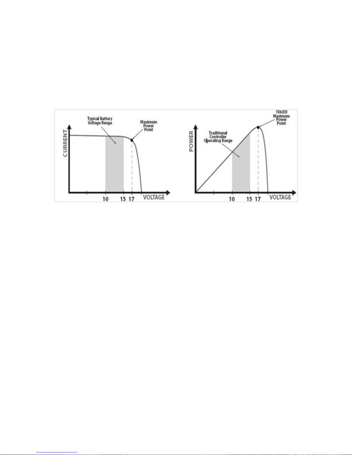
Figure 4-1 shows a typical current VS. Voltage output curve for a nominal 12V off-grid
module.
The array Vmp is the voltage where the product of current and voltage (Amps×Volts) is
greatest, which falls on the ‗knee‘ of the solar module I-V curve as shown in Figure4-1.
Because Traditional controllers do not operate at the Vmp of the solar modules(s),
energy is wasted that could otherwise be used to charge the battery and power system
loads. The greater the difference between battery voltage and the Vmp of the module, the
more energy is wasted.
eTracer-BND MPPT technology will always operate at the Vmp resulting in less wasted
energy compared to traditional controllers.
·Conditions That Limits the Effectiveness of MPPT
The Vmp of a solar module decreases as the temperature of the module increases. In very
hot weather, the Vmp may be close or even less than battery voltage. In this situation,
there will be very little or no MPPT gain compared to traditional controllers. However,
systems with modules of higher nominal voltage than the battery bank will always have
Current vs Voltage in 12V system
Output power in 12V system
Figure 4-1 Nominal 12V solar module I-V curve and output power graph
Page 19
15
an array Vmp greater than battery voltage. Additionally, the savings in wiring due to
reduced solar current make MPPT worthwhile even in hot climates.
4.2 Battery Charging Information
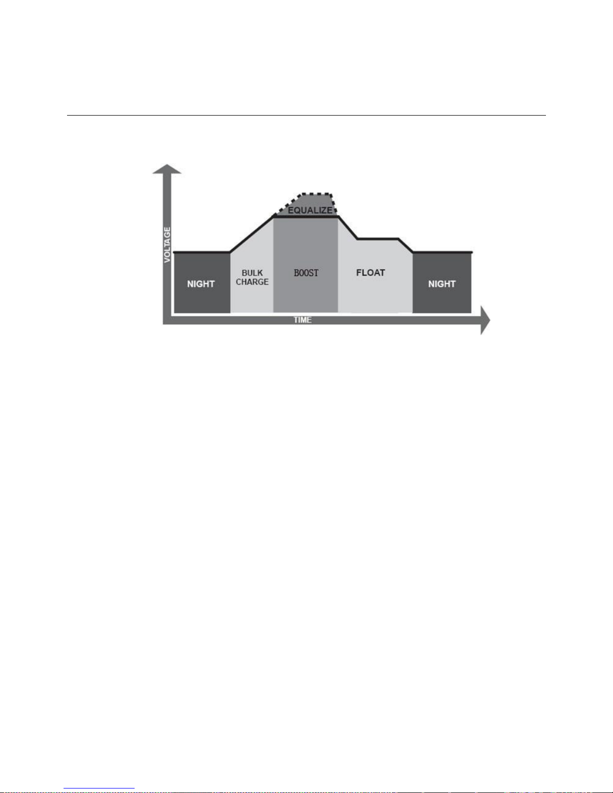
The eTracer-BND has a 4 stages battery charging algorithm for rapid, efficient, and safe
battery charging.
Figura4-2 eTracer-BND charging algorithm
·Bulk Charge
In this stage, the battery voltage has not yet reached boost voltage and 100% of
available solar power is used to recharge the battery.
·Boost Charge
When the battery has recharged to the Boost voltage setpoint, constant-voltage
regulation is used to prevent heating and excessive battery gassing. The Boost stage
remains for some time and then goes to Float Charge. Every time when the controller is
powered on, if it detects not overvoltage, the charging will enter into boost charging
stage.
·Float Charge
After the Boost voltage stage, eTracer-BND will reduce the battery voltage to float
voltage setpoint. When the battery is fully recharged, there will be no more chemical
reactions and all the charge current transmits into heat and gas at this time. Then the
eTracer-BND reduces the voltage to the floating stage, charging with a smaller voltage
Page 20
16
and current. It will reduce the temperature of battery and prevent the gassing and charge
the battery slightly at the same time. The purpose of Float stage is to offset the power
consumption caused by self consumption, while maintaining full battery storage
capacity.
Once in Float stage, should the battery voltage remain below the Boost Return Voltage;
the controller will exit Float stage and return to Bulk charging.
·Equalize
WARNING: Risk of explosion!
Equalizing flooded battery would produce explosive gases, so well
ventilation of battery box is recommended.
NOTE: Equipment damage!
Over-charging and excessive gas precipitation may damage the battery
plates and activate material shedding on them. Too high and equalizing
charge or for too long may cause damage. Please carefully review the
specific requirements of the battery used in the system.
Certain types of batteries benefit from periodic equalizing charge, which can stir the
electrolyte, balance battery voltage and complete chemical reaction. Equalizing charge
increases the battery voltage, higher than the standard complement voltage, which
gasifies the battery electrolyte.
The controller will equalize the battery on 28th each month. The constant equalization
period is 0~180 minutes. If the equalization isn‘t accomplished in one-time, the
equalization recharge time will be accumulated until the set time is finished. Equalize
charge and boost charge are not carried out constantly in a full charge process to avoid
too much gas precipitation or overheating of battery.
NOTE: When the sunshine is weak and Charging current is less than 1.5Amps, the
controller couldn‘t fully follow the maximum power tracking. Therefore, don‘t evaluate
in that condition.
Page 21
17
4.3 LED Indication
Charging LED
Indicator Status
Green Blink Charging
Green OFF No charging
Battery LED
Indicator Status
Green ON Normal
Green slow blink Full
Orange ON Under voltage warning
Red ON Low voltage disconnect
Red Blink Battery over temperature
Green fast blink High volt disconnect
Fault LED
Indicator Status
Red OFF Normal
Red Blink Current abnormal
Charging overcurrent
PV overvoltage
All Indicator
Indicator Fault Status
Blink(Battery LED in Red) Work voltage error
Blink(Battery LED in Orange) Controller over temperature
Page 22
18
4.4 LCD Display & Operation
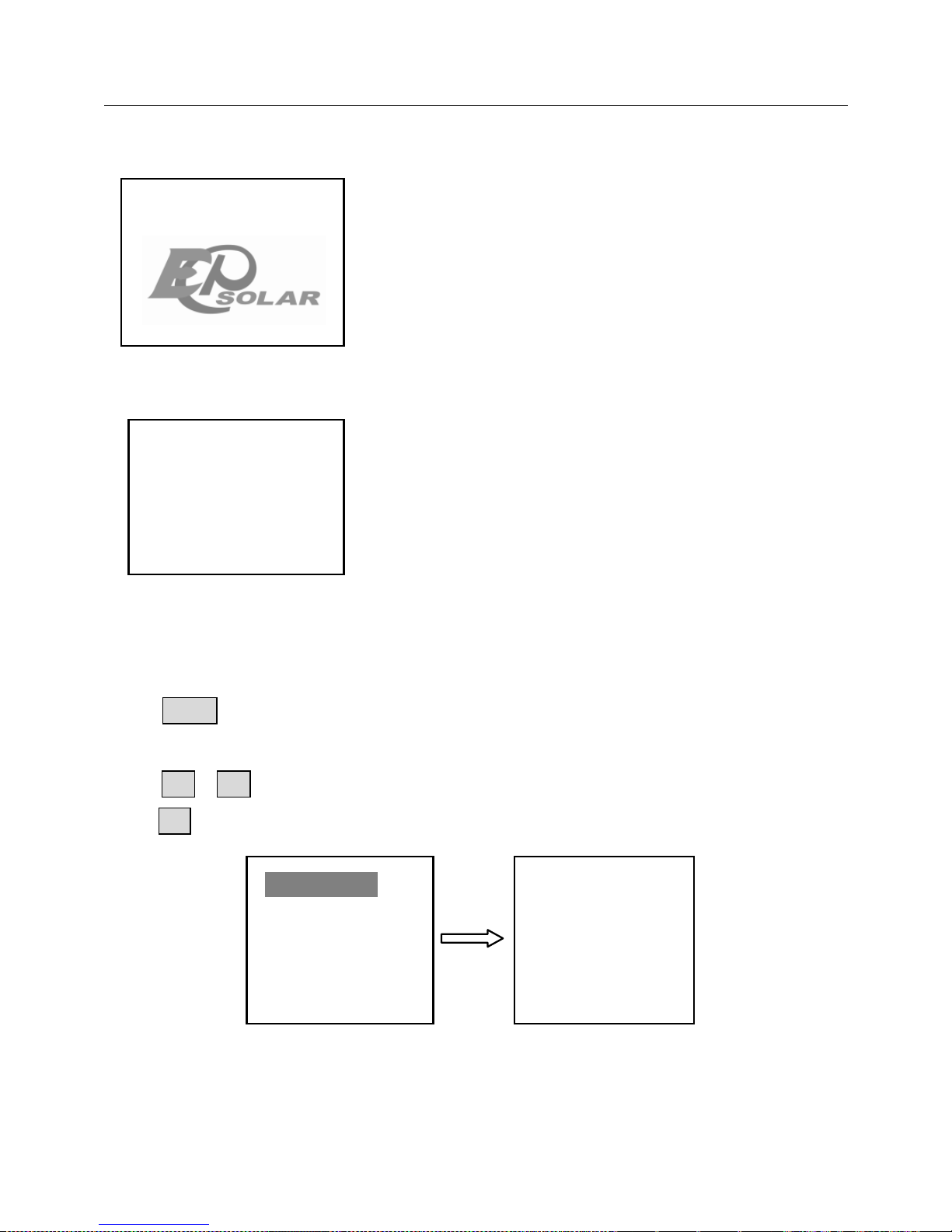
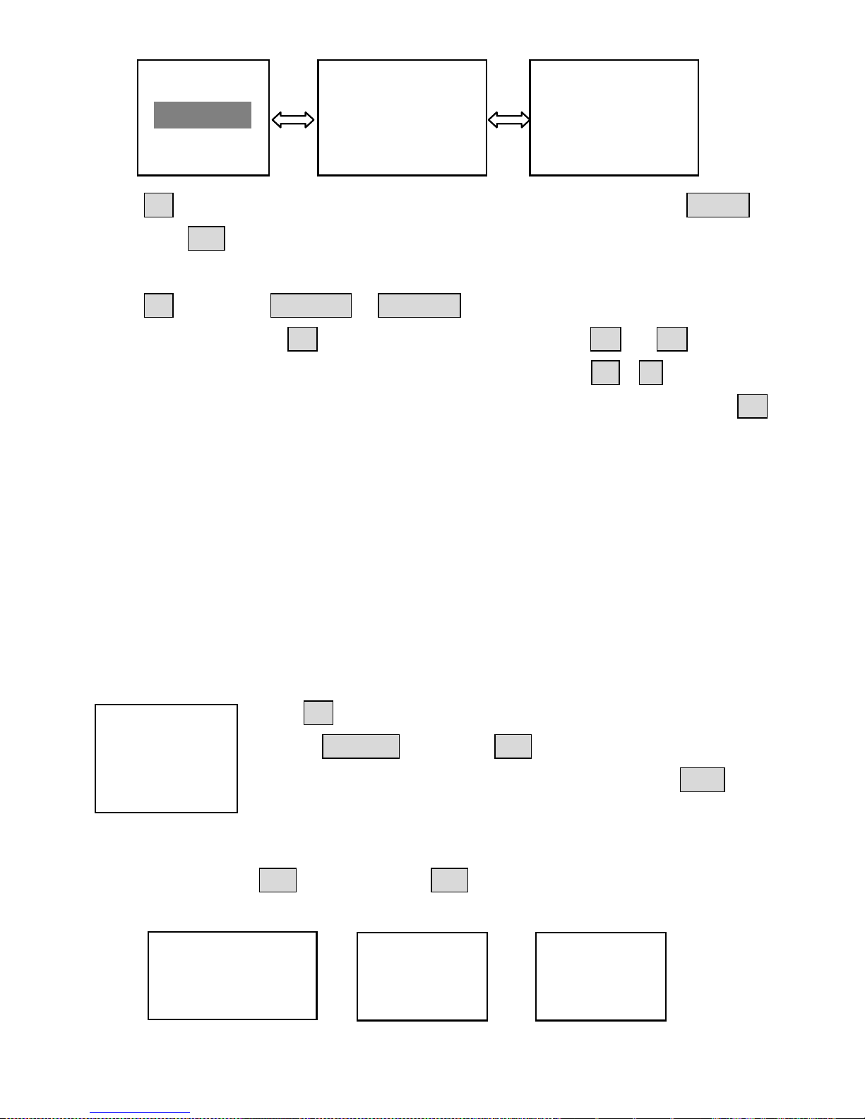
Initialization
LCD will paint the picture as shown on the left as soon
as it is powered on. It indicates that initialization is
normal when the interface goes automatically to the
Rated Info interface.
Rated Info
Rated info of the controller will be displayed. Monitor
interface will be switched after 3 seconds.
Main Menu
Click ESC button to return main menu in any monitoring interface.
There are 9 interfaces for monitoring, as shown in the below picture.
Press ↑ ↓ button to move inverse cursor among 8 menus.
Press OK to enter corresponding interface.
1.Monitoring
2.Log Info
3.Clock Set
4.Local Para Set
5.Control Para
6.Sys Password
7.Default Set
8.Dev Msg
Rated Para.
Rat.Volt 48.0V
Chrg.Cur 60.0A
Efficient Power
Page 23
19
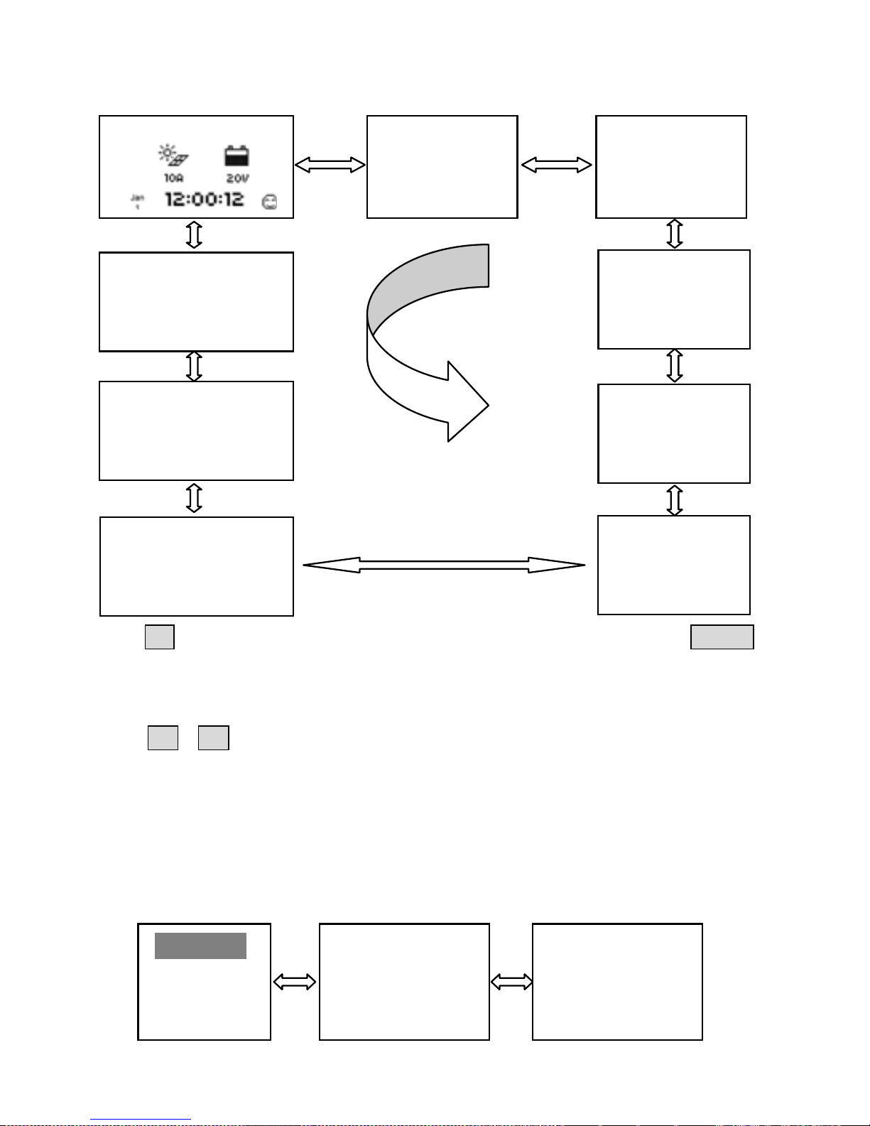
Monitor
There are 9 interfaces for monitoring, as shown below:
Press OK to enter the monitoring interface when the inverse cursor point to monitor
item.
The parameters in monitoring interface are only for browse.
Press ↑ ↓ button to browse the parameters interfaces in turns. There are 5
battery status: Normal, UVW(Under voltage warning), LVD(Low voltage disconnect),
Over Voltage, Over Temperature and 4 charging stages: no charging, equalized, boost,
float.
Log Info
There are two items of log record as shown blew.
<1>Work Log
<2>Alarm Log
Work Log Query
From 2012-01-01
To 2012-06-08
Total:79
No. 1/79
2012-01-01 00:00
Batt Vol 13.3V
Batt Cur 0.0A
Batt. Temp
21ºC
Temp Coefficient
-3mV/ºC /2V
Total Generated
7.50kWh
Batt.Volt
12.4V
Batt. Curr
Batt. Day‘Max
13.5V
Batt. Day‘ Min
Batt. State
Normal
Batt. SOC
Charge State
Float
PV Volt.
Generated Energy
1.5kWh/D
PV Power
Local Temp
24.0 ºC
Page 24
20
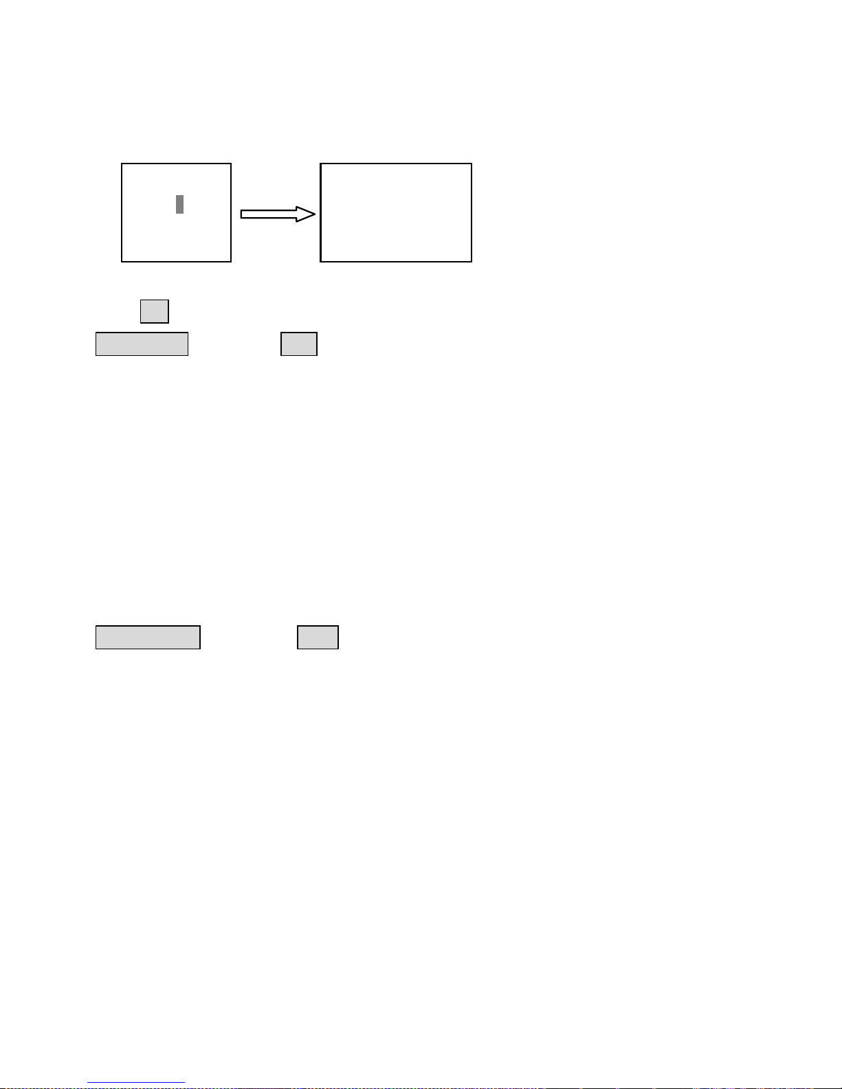
Press OK to enter the monitoring interface when the inverse cursor point to monitor
item. Press ESC button to exit. Work Log and Event Log could be browsed in this
interface, the operation is as follows:
Press OK to enter the Work Log or Event Log interface respectively when the item is
chosen in inverse. Press OK again to enter the Edit Mode. Use ↑ or ↓ button to
move the cursor between the time parameters and data bit. Use + - button to
modify the value and set the period of log for browse. When the period is set, press OK
to enter the corresponding details.
Log Number, time, the voltage and current of battery are included in every work log
item and are shown in the Work Log interface.
warning event sequence number, warning event, start or end time, the fault status and
values are all included in every event log item and are shown in the Event Log
interface.
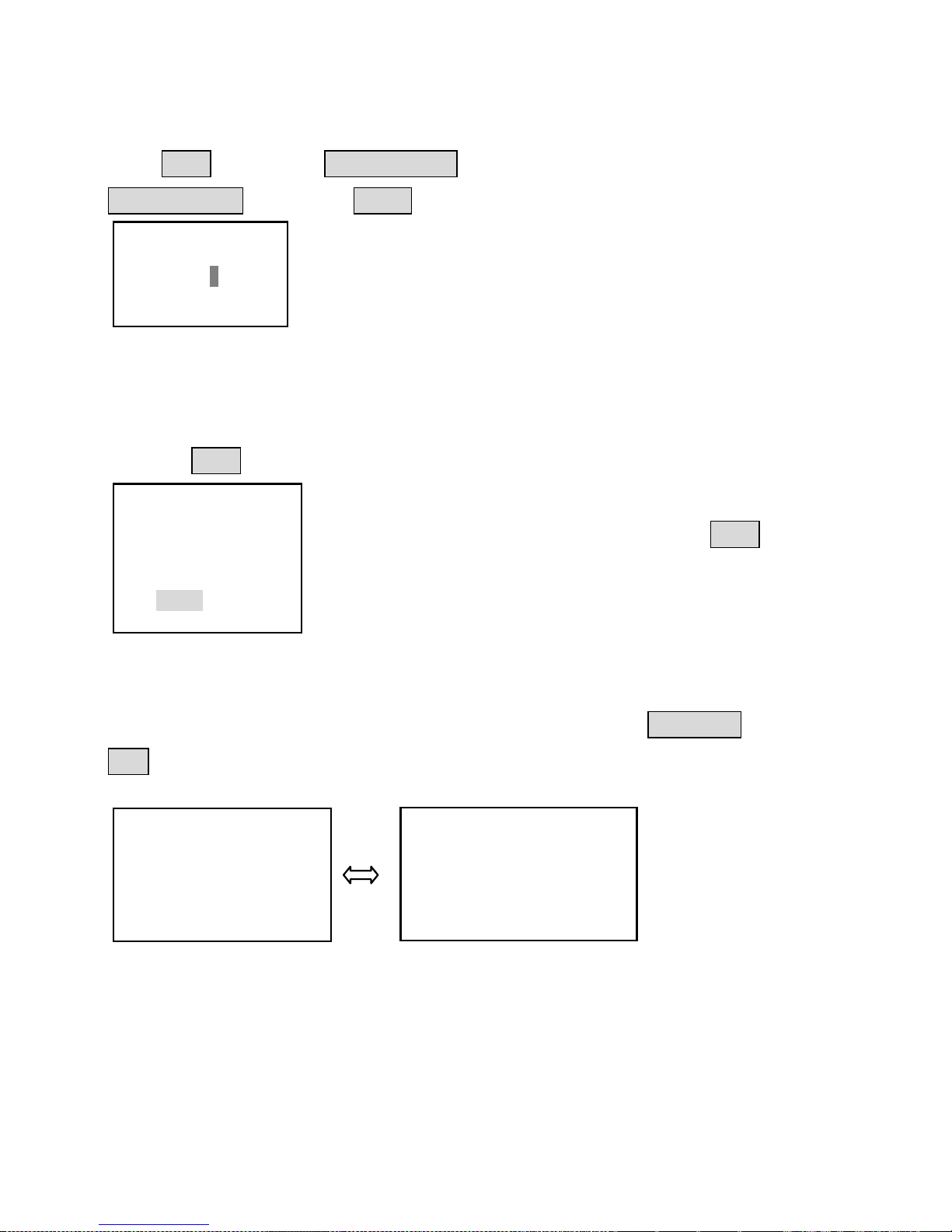
Clock Set
The interface of Clock Set is shown as follow:
Press OK to enter the Clock Set interface when the inverse cursor
point to Clock Set item. Press ESC button to exit.
Date and Time can be adjusted in this interface. Press OK and
input the 6 digit user password and then Date and Time could be
adjusted. The format of date is YYYY-MM-DD; the one of time is HH-MM-SS. When
the set is over, press OK to save or press ESC button to cancel. ―Save success!‖ will
be promoted if adjusted and save operated successfully.
<1>Work Log
<2>Alarm Log
Alarm Log Query
From 2012-01-01
To 2012-06-08
Total:10
No. 1/10
Batt OVD/Begin
2012-01-04 14:20
Para 17.20V
Clock Set
Jan-16-2012
17:12:28
Input Password
000000
Save success!
Save Cancel
Page 25
21
NOTE:The log after the current time will be erased when the clock has be adjusted.
Device Parameter
There are 3 interfaces about device parameter as shown blew:
Press OK to enter the Device Parameter interface when the inverse cursor point to
Device Para item. Press ESC button to exit.
You should input the user password (see above) before setting the parameters.
The first interface shows the 4-digit controller‘s ID in networking and keeps the ID
number unique in the networking or PC software or other device(s) couldn‘t search it.
The 2nd interface shows the backlight time. The range is from 1 to 90 seconds
(60seconds default). ―–‖ means that the backlight is never off. The interval log is from
1 to 30 minutes (10minutes default).
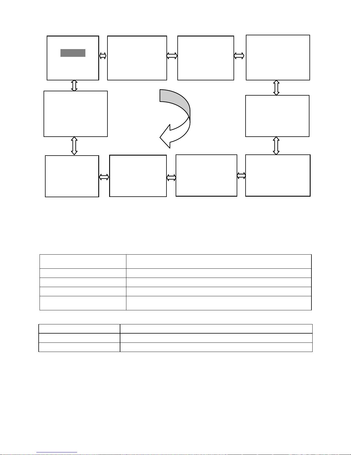
Control Parameter
Press OK to enter the Device Parameter interface when the inverse cursor point to
Control Para item. Press ESC button to exit. There are 10 interfaces for ‗Control
Parameters‘ as shown below.
Local ID
T03-0001
Backlight Time
60 s
Storage Interval
10min
Page 26
22
You should input the user password(see above) before setting the parameters. In
setting mode, all the parameters can be modified. And will immediately effect when
saved. The detail and value range of control parameter are shown in the tables below:
Battery Charging Setting
Battery Type
Note
Sealed (default)
Constant value
GEL
Constant value
flooded
Constant value
User
Defined by user
Battery Charging Mode
Charging Mode
Note
Voltage Compensate
Controlled by voltage(default)
SOC
SOC mode, controlled by SOC charging or discharging value
Boost Rect Volt
26.4V
Low Volt Rect
25.2V
Temp Coefficient
-3mV/℃/2V
Rated Volt
AUTO
Batt Type
SEALED
Batt AH
200AH
Over Volt. Disc.
32.0V
Charge Limit
30.0V
Over Volt. Rect
31.0V
Equalize Charge
29.2V
Boost Charge
28.8V
Float Charge
27.6V
Under Volt Rect
24.4V
Under Volt Warn
24.0V
Low Volt Disc
22.2V
Discharge Limit
21.6V
Equalize Time
60 min
Boost Time
60 min
Batt. Manag.
Char.SOC: 100%
Disc.SOC: 30%
Vol.Com. SOC
Page 27

23
Others
Parameter
Default value
Range
Battery capacity
200Ah
1~9999Ah
Temperature compensate
coefficient
-3mV/ºC /2V
-9~0 mV/ºC /2V
Rated system voltage
Auto
12/24/36/48VDC Auto
Percent of charging
100%
100% constant value(SOC charging mode)
Percent of discharging
30%
10~80% (SOC charging mode)
Battery Control Parameters
All the coefficient is referred to 25℃, and twice in 24V system rate, triple in
36Vsystem rate and quadruple in 48Vsystem rate.
Battery Type
Gel
Sealed
Flooded
User
High Volt Disconnect
16V
16V
16V
9~17V
Charging limit voltage
15V
15V
15V
9~17V
Over Voltage Reconnect
15V
15V
15V
9~17V
Equalization voltage
14.6V
——
14.8V
9~17V
Boost voltage
14.4V
14.2V
14.6V
9~17V
Float voltage
13.8V
13.8V
13.8V
9~17V
Boost return voltage
13.2V
13.2V
13.2V
9~17V
Low voltage reconnect
12.6V
12.6V
12.6V
9~17V
Under voltage recover
12.2V
12.2V
12.2V
9~17V
Under voltage warning
12V
12V
12V
9~17V
Low voltage disconnect
11.1V
11.1V
11.1V
9~17V
Discharging limits voltage
10.6V
10.6V
10.6V
9~17V
Equalize duration
120min
——
120min
0~180min
Boost duration
120min
120min
120min
10~180min
Note:1. When the battery type is sealed, gel, flooded,the adjusting range of equalize
duration is 0 to180min and boost duration is 10 to180min.
2. The following rules must be observed when modify the parameters value in user
battery type (factory default value is the same as sealed type):
Rule1: High Volt Disconnect > Charging limit voltage ≥ Equalization voltage ≥ Boost
voltage ≥ Float voltage > Boost return voltage;
Rule2: High Volt Disconnect > Over Voltage Reconnect;
Rule3: Low voltage reconnect > Low voltage disconnect ≥ Charging limit voltage;
Rule4: Under voltage recover > Under voltage warning ≥ Charging limit voltage;
Rule5: Boost return voltage > Low voltage reconnect;
Page 28
24
Password
Press OK to enter the Password Set interface when the inverse cursor points to
Password Para item. Press ESC button to exit.
Note: The factory default password is “000000”.
Default Set
Under the main menu interface, when the inverse cursor to restore the default option,
press the OK button to enter to restore the default interface.
Under the main menu interface, when the inverse cursor
points to restore the default option, press the OK button to
enter to restore the default interface and clear all logs
including work log and event log. Note: all parameters will be
set to factory default and couldn‘t be recovery.
Device Message
Under the main menu interface, when the inverse cursor to the Dev Msg , press the
OK button to enter to Device Info interface.
The Model, software and hardware version and SN number are shown in this interface.
Default Set
No Yes
Clr Log Record
Retain clear
Sys Password
Old PSW 000000
New PSW 000000
ARM Msg.
Type: ET6415BND
Ver:V02.05+V02.60
SN:0420131210000001
DSP Msg.
Type: ET6415BND
Ver:V02.05+V02.60
SN: 0420131210000001
Page 29
25
5 Protections, Troubleshooting & Maintenance
5.1 Protections
·PV Short Circuit
When PV short circuit occurs, the controller will stop charging. Clear it to resume
normal operation.
·PV Over Voltage
If PV voltage is larger than maximum input open voltage 150V, PV will remain
disconnected and warning until the voltage falls safely below 145V. PV voltage cannot
be too high, otherwise it may damage the controller, please verify the PV parameter.
·PV Over Current
The eTracer-BND controller will limit battery current to the Maximum Battrery
Current rating. An over-sized solar array will not operate at peak power.
·PV or/and Battery Polarity Reversed
Fully protection against PV or/and Battery reverse polarity, no damage to the controller
will result. Correct the miswire to resume normal operation.
·Over Temperature Protection
If the temperature of the controller heat sinks exceeds 85℃, the controller will
automatically start the overheating protection and recover below 75℃.
NOTE: Faults will be cleared every day, so the faults which aren’t caused
by hardware can be solved intelligently.
5.2 Troubleshooting
Charging LED indicator off during daytime when sunshine falls on solar modules
properly
Solution: Confirm that PV and battery wire connections are correct and tight.
Battery LED indicator green fast blink and LCD displaying ‗OVD‘
Probable Cause: Battery voltage is larger than over voltage disconnect voltage (OVD).
Solution: Check if battery voltage too high, and disconnect solar modules.
Page 30

26
Fault LED indicator blink, LCD displaying ‗Current Err‘
Probable Cause: Charging current in three phases is unbalanced.
Solution: Disconnect solar modules and restart the eTracer-BND; if the fault still exists,
please contact the supplier to make maintenance.
Fault LED indicator blink, LCD displaying ‗Over Volt‘
Probable Cause: solar modular output is too high.
Solution: Check solar component parameters matching; the controller will disconnect
the input if the voltage is over 150V and will Recovery below 145V.
Fault LED indicator blink, LCD displaying ‗Over Temp‘
Probable Cause: Heat sinks operational temperature is quite high to 85 ºC or above.
Solution: The controller will automatically stop working. When the temperature is
below 75 ºC , the controller will resume to work.
Cannot connect to the controller via RS-485 or RS-232
Probable Cause: RS-485 serial baud rate setting error or serial-USB adapter incorrect
configuration.
Solution: Check serial baud rate is set to 115200bps or not and choose the right COM
port; If using a serial-USB adapter, verify that the adapter software is installed and a
serial COM port has been mapped.
5.3 Maintenance
The following inspections and maintenance tasks are recommended at least two times
per year for best controller performance.
Check that the controller is securely mounted in a clean and dry environment.
Check that the air flow and ventilation around the controller is not blocked. Clear all
dirt or fragments on the heat sink.
Check all the naked wires to make sure insulation is not damaged for serious
solarization, frictional wear, dryness, insects or rats etc. Maintain or replace the wires if
necessary.
Tighten all the terminals. Inspect for loose, broken, or burnt wire connections.
Page 31
27
Check and confirm that LED or LCD is consistent with required. Pay attention to any
troubleshooting or error indication .Take necessary corrective action.
Confirm that all the system components are ground connected tightly and correctly.
Confirm that all the terminals have no corrosion, insulation damaged, high
temperature or burnt/discolored sign, tighten terminal screws to the suggested torque.
Inspect for dirt, insects and corrosion, and clear up.
Check and confirm that lightning arrester is in good condition. Replace a new one in
time to avoid damaging of the controller and even other equipments.
Warning:Risk of electric shock!
Make sure that all the power is turned off before above operations,
and then follow the corresponding inspections and operations.
Page 32
28
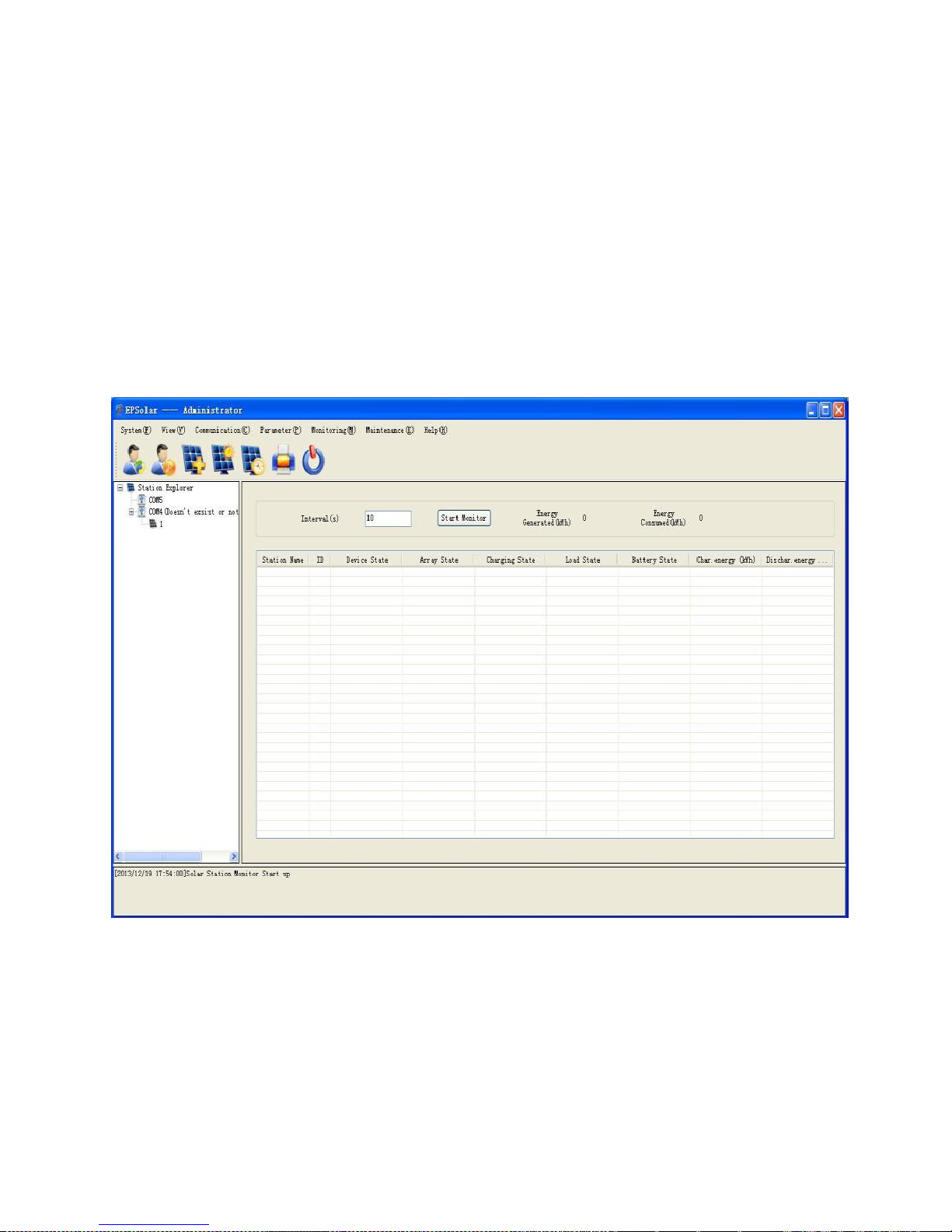
6 PC Software
The eTracer-BND controller can be connected to a common PC monitoring software by
supporting USB communication cable developed by the EPsolar company. Monitoring
software can remote single or more controllers to modify the parameters and others in
the PV system management (username: administrator, password: 111111 as default).
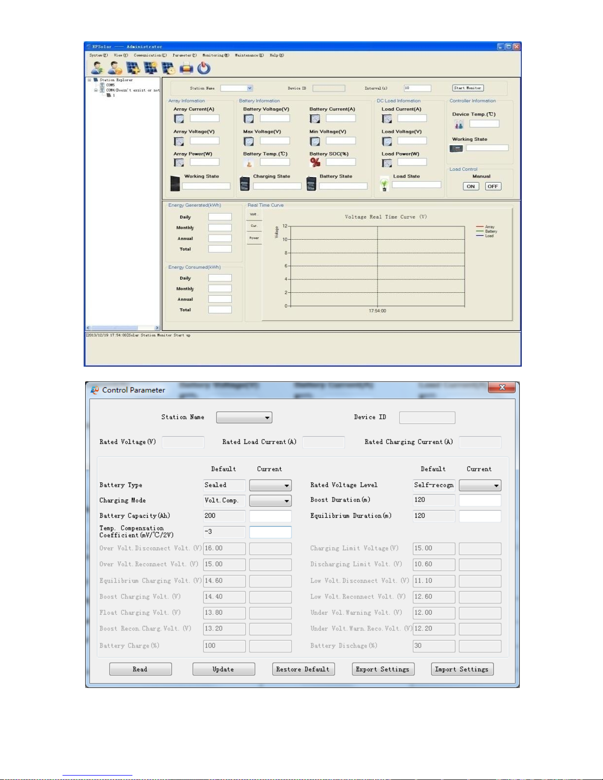
See the specific instructions related software user guide. Software interfaces are shown
below:
Figure6-1 Globe Monitoring
Page 33
29
Figure6-2 Real Time Monitoring
Figure6-3 Control Parameter
Page 34

30
7 Warranty
The eTracer-BND charge controller is warranted to be free from defects for a period of
TWO (2) years from the date of shipment to the original end user.
• Claim Procedure
Before requesting warranty service, check the operation manual to be certain that there
is a problem with the controller. Return the defective product to us with shipping
charges prepaid if problem cannot be solved. Provide proof of date and place of
purchase. To obtain rapid service under this warranty, the returned products must
include the model, serial number and detailed reason for the failure, the module type
and size, type of batteries. This information is critical to a rapid disposition of your
warranty claim.
If the products failure is caused by customers‘ misuse or not following the manual,
EPsolar won‘t be responsible for the free maintenance. We will ask for the raw material
cost. And please refer to above procedure.
Page 35

31
8 Specifications
Electrical Parameters
ET4415BND ET6415BND
Nominal System Voltage 12/24/36/48VDC Auto
Nominal Battery Current 45A 60A
Maximum Solar Input Voltage 150V
Battery Voltage Range 8~72V
Maximum Input Power
12V: 600W 800W
24V: 1200W 1600W
36V: 1800W 2400W
48V: 2400 W 3200W
Self Consumption 1.4~2.2W
Grounding Common Negative Grounding
Mechanical Parameters
ET4415BND ET6415BND
L x W x H
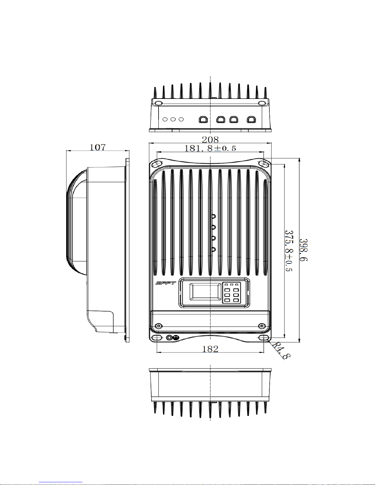
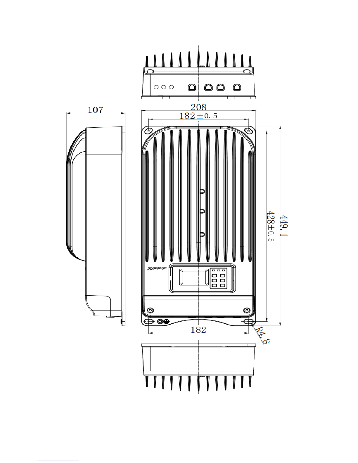
L: 398.6(15.7)mm(inch) 449.1(17.7)mm(inch)
W: 208(8.2)mm(inch) 208(8.2)mm(inch)
H: 107(4.2)mm(inch) 107(4.2)mm(inch)
Net Weight: 4.3kg 5.5kg
Terminal: 35mm2 35mm2
Mounting Hole: Φ10
Environmental Parameters
LCD Temp -20℃ ~ +70℃
Ambient Temp -25℃ ~ +55℃
Storage Temp -30℃ ~ +85℃
Humidity ≤95%, N.C.
Enclosure IP20
Page 36

32
Protection
Solar input short protection
Solar input reversed polarity protection
Solar input reverse current protect at night
Battery reversed polarity protection
Battery over voltage disconnect protection
Battery over voltage reconnect protection
Battery over temperature disconnect protection
Controller over temperature disconnect protection
Abbreviation
HVD High voltage disconnect
LVD Low voltage disconnect
OVT over temperature
UVW Under voltage warning
Page 37
33
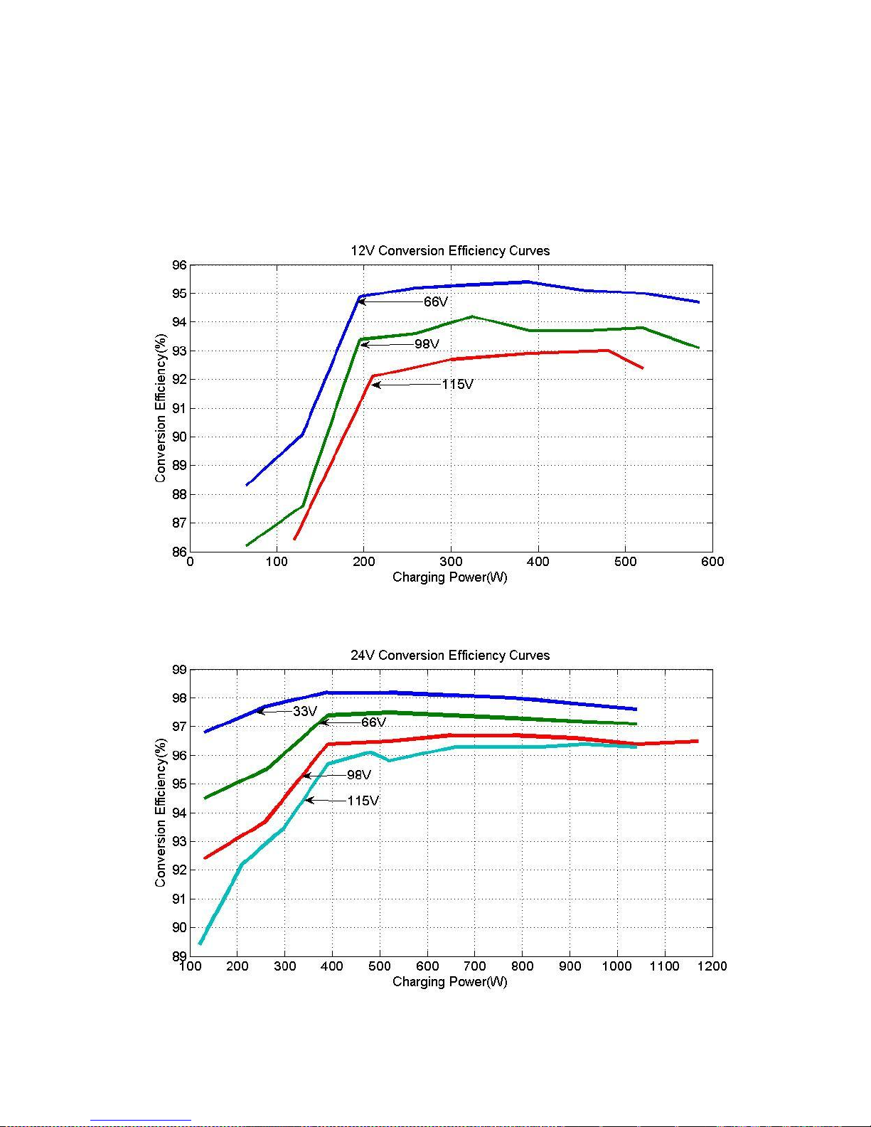
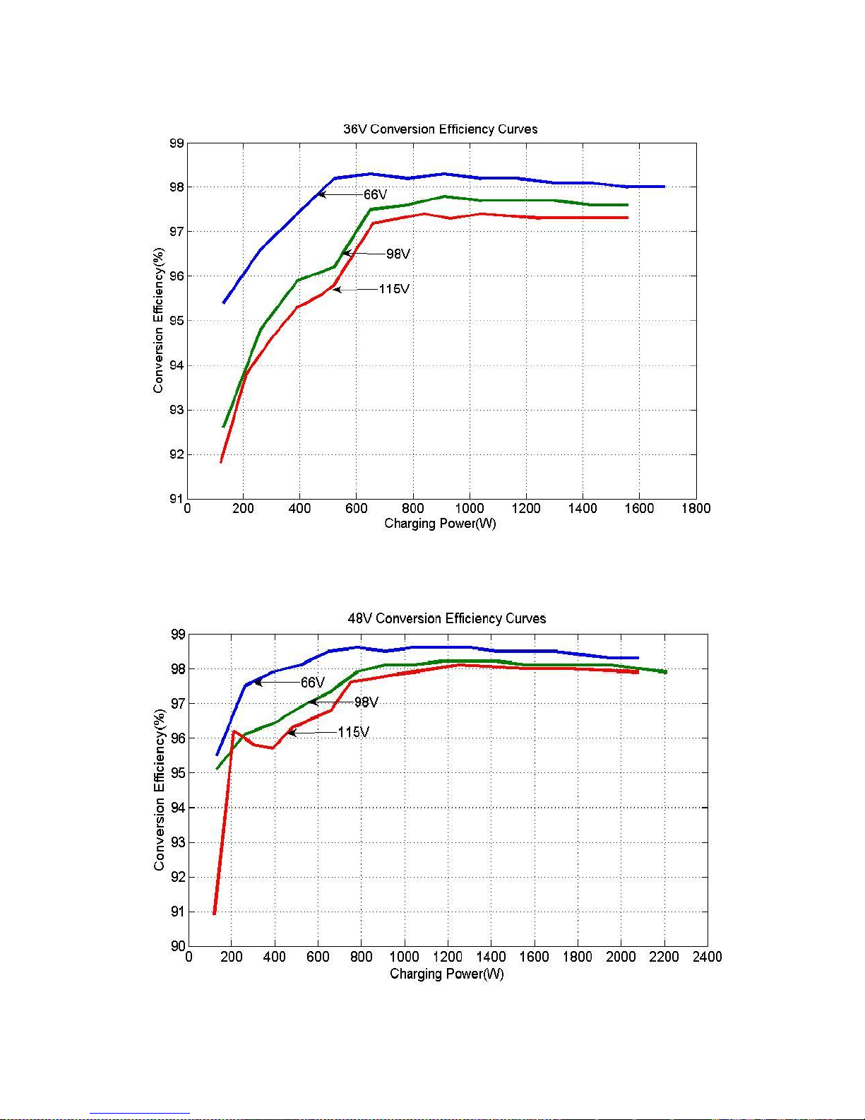
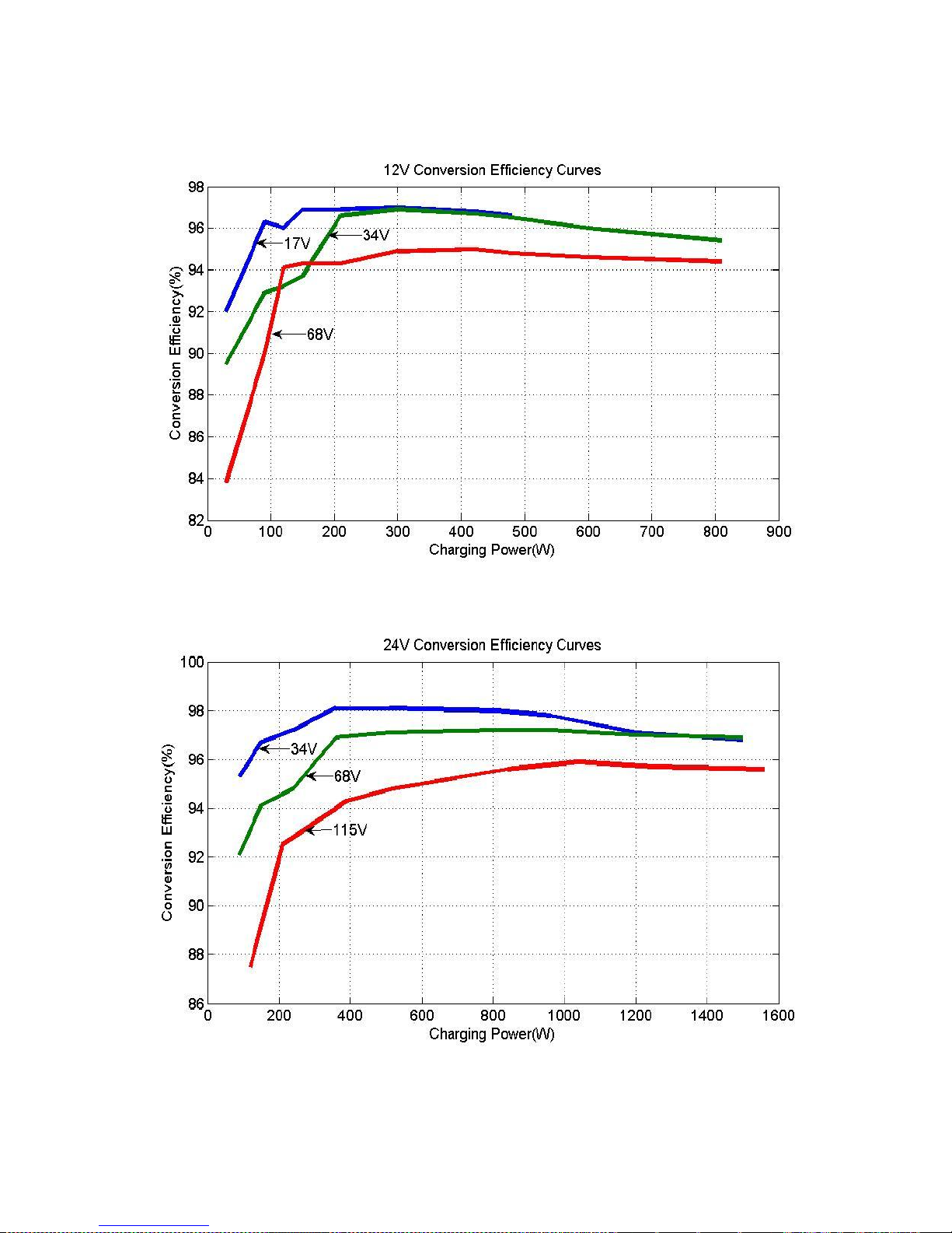
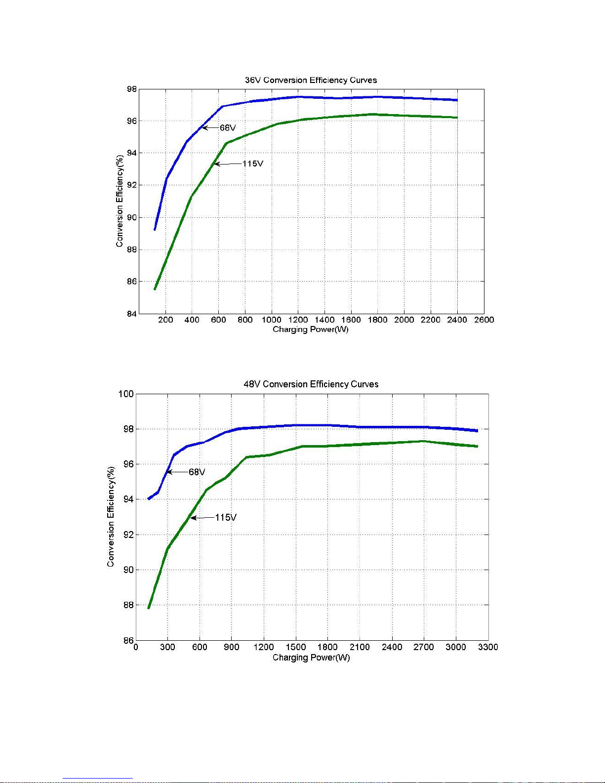
9 Conversion Efficiency Curves
Illumination Intensity: 1000W/m2 Temperature: 25℃
Test model: ET4415BND
1. Solar MPPT Voltage(66V, 98V, 115V) / System Voltage(12V)
2. Solar MPPT Voltage(33V, 66V, 98V, 115V) / System Voltage(24V)
Page 38
34
3. Solar MPPT Voltage(66V, 98V, 115V) / System Voltage(36V)
4. Solar MPPT Voltage(66V, 98V, 115V) / System Voltage(48V)
Page 39
35
Test model: ET6415BND
1. Solar MPPT Voltage(17V,34V,68V) / System Voltage(12V)
2. Solar MPPT Voltage(34V,68V,115V) / System Voltage(24V)
Page 40
36
3. Solar MPPT Voltage(68V,115V) / System Voltage(36V)
4. Solar MPPT Voltage(68V,115V) / System Voltage(48V)
Page 41
37
10 Dimensions
ET4415BND Dimensions(Unit:mm)
Page 42
38
ET6415BND Dimensions(Unit:mm)
Version:V1.4
Page 43

Page 44

BEIJING EPSOLAR TECHNOLOGY CO., LTD.
Tel: +86-10-82894112 / 82894962
Fax: +86-10-82894882
E-mail:[email protected]
Website: http://www.epsolarpv.com/
 Loading...