

Page 1
1
2
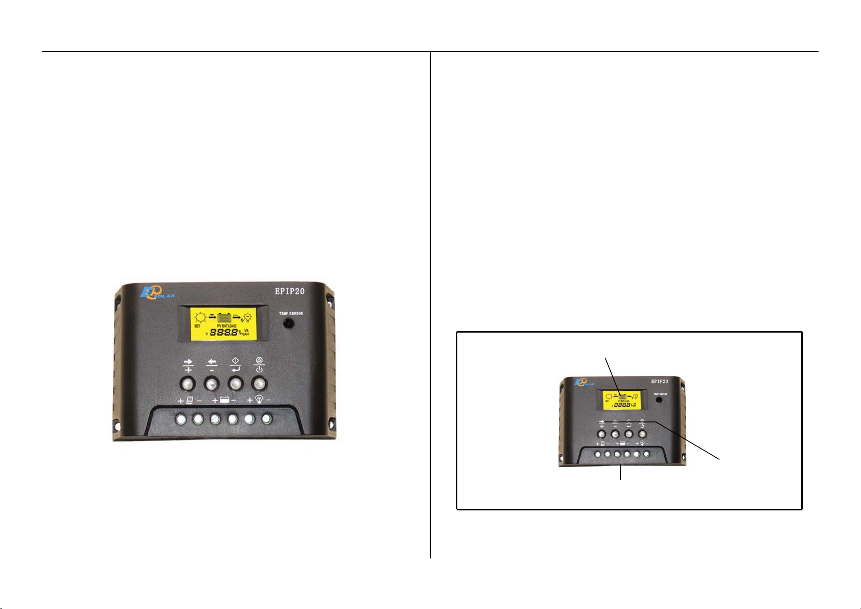
Terminal
LCD monitor
4 key setting
EPIP-20 LT SERIES
1 Characteristics
●Battery Ah setting
●Operating and setting easily
●Automatic selection of voltage 12/24V
SOLAR CHARGE CONTROLLER
─for solar PV system
INSTRUCTION MANUAL
Charging Control
●PWM charging
●Temperature compensation. Boost, equalizing, float charging
●Four work mode: ON/OFF, lighting control, Lighting + hours on,
ON/OFF+exact time
Protecting Function
●TVS lighting protecting
●Over-load, short circuit, polarity reverse protection, electronic fuse.
Display
●LCD display specially designing for solar system
●LCD display: all system parameters in digital value, system status as
symbols
●Accurate clock show
2 Controller panel instructions
3 Installations:
Page 2
3
4
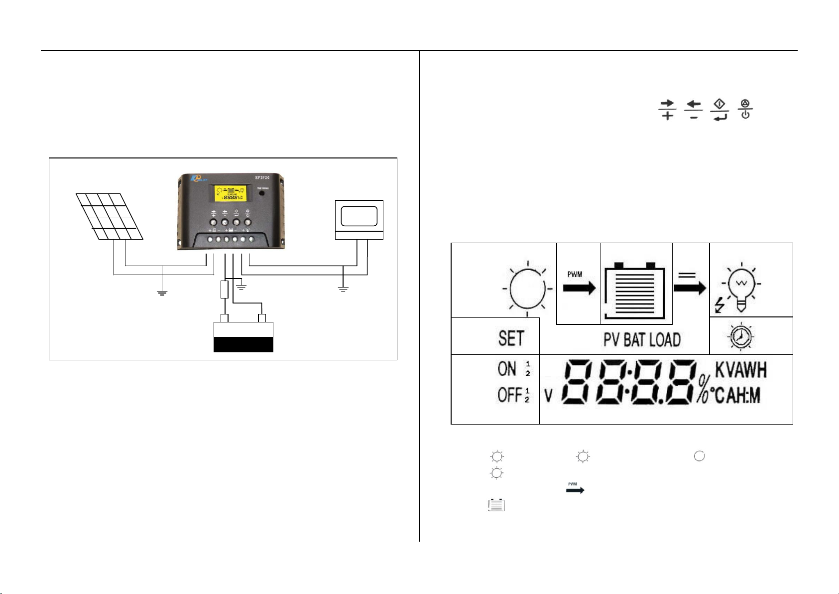
System assembly
+
-
+ -
+
Solar Module
Battery
Fuse
Load
Load symbol
Battery status
Connect the individual components to the symbols provided, they are
solar panel, battery and loads in order. Only install the regulator near the
battery on a suitable surface. This surface should be solid, stable, even,
dry and nonflammable. The battery cable should be as short as possible
(1-2m) and have a suitable cable diameter size to minimize loss, e.g. use
2.5mm
2
at 10A; use 4mm
Observe the following connection sequence during commissioning:
1) Mount the controller to a vertical surface. Allow space above and
2
at 20A.
6.The negative battery is grounded or ground connected as the above.
4. Operation & instructions:
1 Keys & instructions(from left to right):
K1:Reading status, switch to next figure;Setting status, switch to next
function or increase the setting data.
K2:Reading status, switch to the previous figure; setting status, switch to
the previous function or decrease the setting data.
K3: On reading status, press K3, then on setting status; on setting status,
press K3, and save the data, back to reading status.
K4:Cancel/power switch, on setting status, no saving with K4. On reading
status, K4 is power switch while loads are working. Recovery key
while it’s short–circuited or over load(with ON/OFF mode).
below the controller for air flow. Note: the mounted ambient
temperature should not be over the working temperature of controller
(-10℃~60℃);
2.Connect the polarity + of battery to the fuse,and then connect the battery
to the controller. The current of fuse should be chosen 3-4 times of rated
current. Note the plus and minus.
3. Connect the photovoltaic module to the charge regulator - plus and
minus
4. Connect the consumer to the charge regulator –plus and minus
Please observe that the automatic adjustment to 12V/24V
systems does not function properly, if this sequence order is not
followed. An improper sequence order can damage the battery!
5.The parameters can be set depending on the user’s need.
2 Display instructions: LCD display as the setting mark:
1) sun symbol, on is daytime and on is night time;
flashing shows over voltage.
2)Charging mode . PWM charging
3) battery. The strips inside show the status of charging or
discharging and current capacity percentage.
If discharging, the strips will reduce.
Page 3
5
6
BAT
XX.X
V
BAT
XXXX
AH
BAT
XX.X ℃
PV
XX.X A
LOAD
XX.X A
BAT
V
XXXX
PV
XX.X V
XXXX
XX XX
XX:XX H:M
Year,month
date
hour:minute
displayed in
sequence.
If charging, the strips will increase.
Without charging or discharging, the strips inside will remain the
status.
Every strips equals 10% of battery capacity.
shows status of battery. flashes when over discharging.
It stops flashing when goes back to normal charging.
4) DC output.
5) load,shows load and trouble status.
is on when the load is in normal, symbol display when
output is on.
Load symbol is flashing when over loading, reduce the load,
then press K4 for resume.
While short circuit protection, flashes, return to normal
automatically after 10 minutes. If there are 2 short circuit
protection in concession in 11 minutes, users need check loads
and connects, then press K4.
6)LCD displays “PV”, “BAT”, “Load” for solar module, battery or load
separately.
7)“SET” on goes to reading status, “SET” flashing is on setting status
8) , , is the load ON or OFF symbol, for example, ON 1 is the first load
on, OFF 2 is the second load switched off.
9) at bottom of LCD display shows parameters.
10) Displays in lower right: V-Voltage, A-ampere, AH-Battery
Capacity, ℃-Temperature, H:M-Time
11)v XX% the percent of available voltage of battery, the current
capacity of battery.
Please observe that the accuracy of the regulator’s display is not
comparable to that of a measuring device.
4.Operation instructions:
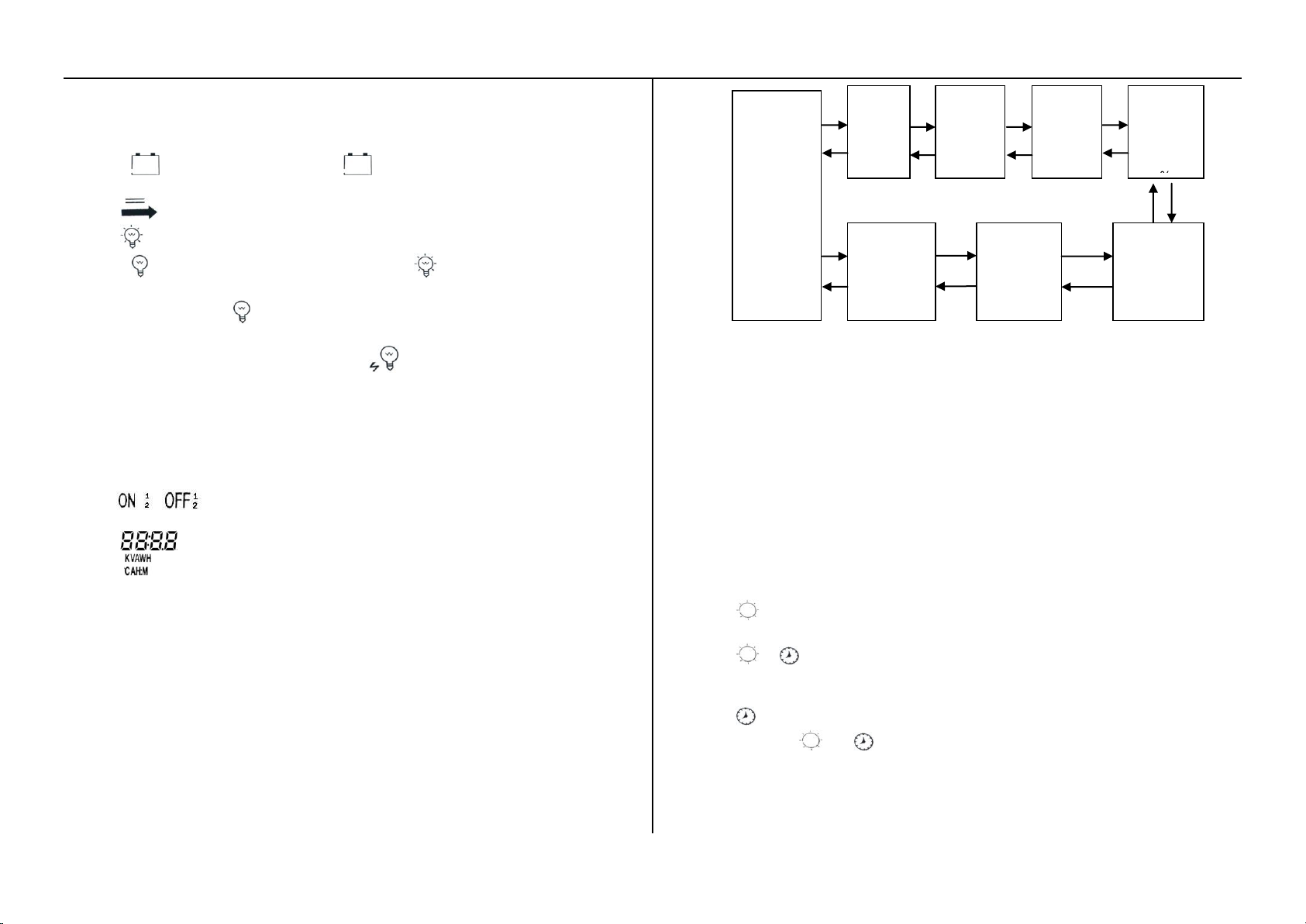
4.1 Reading specifications: On reading status, press K1, K2, LCD will
repeat the following specifications.
4.3Battery capacity modify:
While display battery capacity XXXX AH, press K3 into setting mode,
battery unit “AH”& “SET” is flashing, modify the data through K1/K2,
press one time, battery capacity will be up/down 10, the maximum is
5000, the minimum is 50; Press K3 for saving or K4 for back to the
reading status.
The default value is 500AH.
4.4Load control setting:
Four control mode: lighting control, lighting+hours ON, ON/OFF on
exact time, ON/OFF,, When LCD displays load current, press K3 and
“SET” flashes. Operate K1, K2 to meet user’s need and it will be
displayed by icon on the right of the display. Press K3 to return to
reading status.
Load control modes:
1) , lighting control. The loads will be connected or disconnected
automatically when the controller detects the light.
2) + , lighting+hours on. The loads can start working
automatically when the controller detects the lights, and then hours
off , which depends on the hours you set.
3) ,ON/OFF on exact time. Load on or off on exact setting time.
4) Without or , its ON/OFF mode. The load output will be ON or
OFF when you press the switch.
The default load mode is ON/OFF.
4.5 Time setting operation:
Note: the whole time setting hours is 24 hours.
Page 4
7
8
4.5.1 Real time adjustment
When LCD displays time to be adjusted:: Press K3 for two times
and display “SET”
Press K1 or K2 to change the year, month and day automatic and
circlely
Press K3, “SET” flashing, and modify the data by K1 and K2, note:
only the last two numbers can be modified.
Press K3 to confirm the modification and save the data; Press K4
to cancel the modification and return to the second step, and
“SET” stop flashing.
Press K4 two times and return to “reading status”, year, month,
day, hour:minute will repeat in display ever 3 seconds.
4.5.2” Lighting + hours ON” time adjustment
When LCD displays time to be adjusted:: Press K3 for two times
and display “SET”
Press K1 to display “on hours” see following:
Press K3 for one time and “SET” flash
Modify the hours between 1~12 by K1 and K2
Press K3 to confirm the modification and save the data; Press K4
to cancel the modification and return to the second step, and
“SET” stop flashing.
Press K4 for one time and turn to “reading status”
4.5.3”Exact time” adjustment
When LCD displays time to be adjusted:: Press K3 for one time
and turn to reading status for time.
Press K1,K2 and turn to the months of the first season.
Press K3 for one time and turn to the reading status for the first
season.
Press K1,K2, and will display the months of first season, ON 1
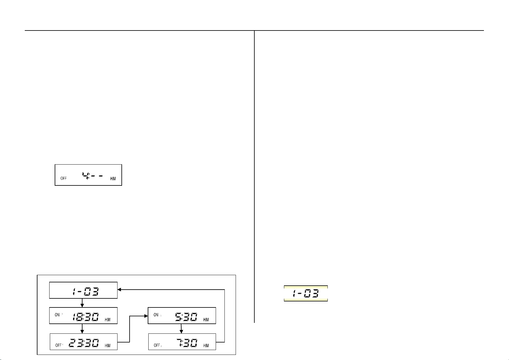
and OFF 1, ON 2 and OFF 2, the arrowhead of the below picture
shows the display order.
Press K3, “SET” and H of H:M flashes, user can modify hours by
K1,K2
Press K3 to confirm the modification and save the data, and
return to the fourth step; Press K4 to cancel the modification and
return to the fourth step, and “SET” stop flashing.
When modify Hour and Minute, H will be modified first. Press K3 and turn
to M modification. Press K3 again, confirm the modification and save the
data, and return to the fourth step; Press K4 to cancel the modification and
return to the fourth step, and “SET” stop flashing.
Press K4 for two times, and turn to reading status.
The default time data is 0, and the controller will follow the last data setting.
The modification for the last month of the first season:
When displaying the first season, press K3 for one time and
“SET” flashing;
Adjust data for month between 1~12 by K1-K2
Press K3 to confirm or Press K4 to cancel. “SET “ stop flashing,
return to the fourth step above.
Modification for H and M:
When LCD displays time to be adjusted: Press K3, “SET” and H
of H:M flashes, user can modify hours
User can adjust data 0~23 by K1/K2
Press K3 again, save data of hours and then turn to modify
minute, “SET” and M of H:M flashes.
User can adjust data 0~59 by K1/K2.
Press K3 and save the modified data, if not saved, then press K4
to return select status-“SET” not flash.
Note: the EXACT TIME Control can be divided to 4 seasons, for example:
1 is the season no. 3 is the last month of season.
Customers can also set 1-12, that means the whole year will have one
season, and the controller will work same during the whole season.
Page 5
9
10
Type
EPIP20-LT
Rated charging current
10A(max12A)
15A(max18A)
20A(max23A)
Rated load current(Ie)
10A
15A
20A
Over load, short circuit
protection
1.25 times of Ie for 60secs,1.5 times of Ie by for 5secs overload protection;
≥3 time of Ie short circuit protection
Self consumption
Control mode:<15 mA, LED & LCD display <15mA,Total: <30mA
System voltage
12/24V AUTOWORK,
Work temperature
industrial:-20℃ to +70℃
Battery capacity
Battery in parallel from 50AH to 5000ah
Boost charging
14.8V;×2/24V
equalizing charging
14.4V;×2/24V
Float charging
13.6V;×2/24V
Low voltage disconnect
11.1V;×2/24V
Low voltage reconnect
12.5V;×2/24V;
Temperature
5mv/℃/2v;
Over discharge voltage
11.4V; ×2/24V;×4/48V
Control mode
PWM charging mode & ON/OFF mode for options, control point voltage is
the intelligent compensation modify of the battery.
Problems
Troubleshooting
Sun symbol
flashing without
setting
Battery over voltage. Open circuit of battery. Check if the
battery cable connect properly, or disconnect all
components and reconnect.
Battery symbol
flashing without
output
Over discharging
The load
symbol flashing
Overload occurs, remove some loads and then press
K4.
Load and short
circuit symbol
flashes
Short circuit protection, check if the loads connect
properly,remove some loads with trouble and then press
K4.
Each season has two working period. And will show as ON1、OFF1,ON2、
OFF2. ON1, OFF1 is for the first period, ON2, OFF2 is for the second
period. The whole period is 24 hours. ON1 to OFF 2 is 24 hours.
5 Safety and Protection
The controller is with intelligent protection against over voltage, over
current, short circuit, polarity reverse and lightning. The LCD displays
have warning indicates of over voltage, over current and short circuit.
Note: TVS lighting protection is the last necessary protection. User need
choose professional TVS system in the areas with frequent lightning
weather. If the controller without TVS system is damaged by lightning, it
will not be guaranteed.
6 Guarantee & Customer service
One year warranty, or contact your authorized distributor. Used
improperly and damaged by people, the controllers are not guaranteed.
7 Specifications
8 Problems & Troubleshooting:
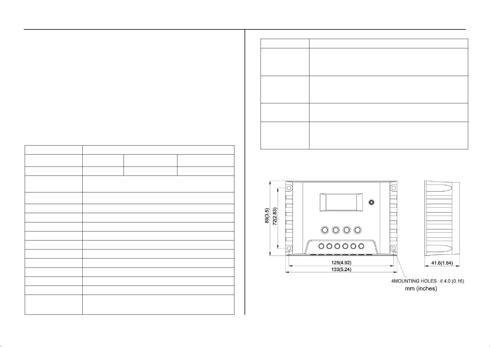
8. MECHANICAL SPECIFICATIONS
 Loading...