

Page 1
EPS Stromversorgung GmbH
Telefon +49 (0)821 570451-0
Electronic Power Supplies
Fax +49 (0)821 570451-25
Alter Postweg 101
D-86159 Augsburg
www.eps-germany.de
M a n u a l
E P S / M P
Page 2

Page 3

Page 4

Software version: V21
June 2014
Page 5

Technical Specifications
Table of Contents
Technical Specifications .............................................................................................................................................. 4
Ambient Conditions ............................................................................................................................................................ 4
Input Specifications ............................................................................................................................................................ 4
Output Specifications ......................................................................................................................................................... 4
AI Interface ......................................................................................................................................................................... 5
RS 232 ................................................................................................................................................................................. 5
RS 485 ................................................................................................................................................................................. 5
Technical Drawing ............................................................................................................................................................... 6
Important Safety Instructions ..................................................................................................................................... 7
Initial Operation .................................................................................................................................................................. 7
Unpacking ........................................................................................................................................................................... 7
Setting Up ........................................................................................................................................................................... 7
Visual Inspection ................................................................................................................................................................. 7
Mains Operation ................................................................................................................................................................. 7
Functional Description ................................................................................................................................................ 8
General Settings ......................................................................................................................................................... 9
Front Panel Description ...................................................................................................................................................... 9
Configuration ...................................................................................................................................................................... 9
Contrast ............................................................................................................................................................................ 10
Voltage Settings........................................................................................................................................................ 10
U
limit
and I
limit
..................................................................................................................................................................... 10
OVP (Over Voltage Protection) ......................................................................................................................................... 10
AI-Type .............................................................................................................................................................................. 10
Remember Last Setting ..................................................................................................................................................... 10
Interface parameter (Option) ........................................................................................................................................... 10
Front Panel Operation .............................................................................................................................................. 11
Display and Settings .......................................................................................................................................................... 11
Current measurement values (Display) ................................................................................................................... 11
Main display ............................................................................................................................................................ 11
Operating modes .............................................................................................................................................................. 12
Main display overview ............................................................................................................................................ 12
Operating Mode description ................................................................................................................................... 13
Universal interface (Option) ..................................................................................................................................... 14
Commands ........................................................................................................................................................................ 14
Format ..................................................................................................................................................................... 14
Instruction Set ......................................................................................................................................................... 15
Quick view of commands ........................................................................................................................................ 15
Detailed description of commands ......................................................................................................................... 16
Response String ....................................................................................................................................................... 24
Ext. Control: Computer ............................................................................................................................................. 25
GPIB .................................................................................................................................................................................. 25
Status Word............................................................................................................................................................. 26
ESR-Register - Event-Status-Register....................................................................................................................... 26
RS232 interface ................................................................................................................................................................. 26
Interface Reconfiguration ....................................................................................................................................... 28
RS485 Interface ................................................................................................................................................................. 28
Interface Reconfiguration ....................................................................................................................................... 29
Page 6

Technical Specifications
2
Ext. Control: AI Interface (Option) .............................................................................................................................29
Pin Assignment AI Interface .............................................................................................................................................. 30
Analog Input ..................................................................................................................................................................... 30
Set Point U (U
Set
) ..................................................................................................................................................... 30
Set Point I (I
Set
) ........................................................................................................................................................ 31
Set Point OVP (U
OVP
) ................................................................................................................................................ 31
Analog Output .................................................................................................................................................................. 31
Monitor Set Point U (U
mon
) ...................................................................................................................................... 31
Monitor Set Point I (I
mon
) ......................................................................................................................................... 31
Monitor Actual Value P (P
mon
) ................................................................................................................................. 31
Analog Output OVP (U
OVPmon
) .................................................................................................................................. 32
Monitor Output Voltage (U
Istmon
) ............................................................................................................................ 32
Monitor Output Current (I
Istmon
) .............................................................................................................................. 32
Digital Input ...................................................................................................................................................................... 32
Activation (Ext. Control) .......................................................................................................................................... 32
Soft-Interlock........................................................................................................................................................... 32
Blocking (Standby) ................................................................................................................................................... 32
Digital Output ................................................................................................................................................................... 32
Blocking (Standby) ................................................................................................................................................... 32
Const. Voltage mode (CV) ................................................................................................................................................. 33
Error .................................................................................................................................................................................. 33
Ext. Control: Ethernet (LAN) ......................................................................................................................................33
Manual Assignment of an IP under Microsoft Windows® ................................................................................................ 33
Monitoring the device via browser................................................................................................................................... 34
Controlling the device via Telnet ...................................................................................................................................... 34
Controlling the device via browser ................................................................................................................................... 35
Ext. Control: USB .......................................................................................................................................................35
Interface Reconfiguration ................................................................................................................................................. 35
Data Log Function (Option) ........................................................................................................................................36
Format of the saved Data ................................................................................................................................................. 36
Script Mode ...............................................................................................................................................................36
Executing/Loading a Script ............................................................................................................................................... 36
Commands ........................................................................................................................................................................ 37
Syntax ...................................................................................................................................................................... 37
Quick view of commands ........................................................................................................................................ 37
Detailed description of commands ......................................................................................................................... 37
Controller ..................................................................................................................................................................41
Controller Structure PVsim Mode and User Mode ........................................................................................................... 42
Controller Structure UIP Mode ......................................................................................................................................... 42
Controller Structure UIR Mode ......................................................................................................................................... 42
Controller parameters ...................................................................................................................................................... 43
Sense Mode ...............................................................................................................................................................44
Load connection without Sensor Conductor .................................................................................................................... 44
Load Connection with Sensor conductor .......................................................................................................................... 44
Load Distribution without Sensor Conductor ................................................................................................................... 44
Appendix ...................................................................................................................................................................45
Equivalent leakage current measurement according to VDE 0701 .................................................................................. 45
Notes .........................................................................................................................................................................47
Page 7

Technical Specifications
Page 8
Technical Specifications
4
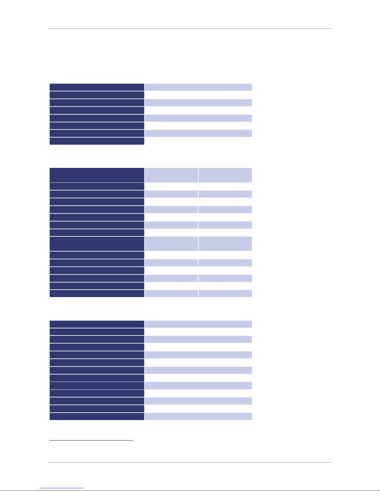
TECHNICAL SPECIFICATIONS
A
MBIENT CONDITIONS
Cooling
Fan
Operating temperature
0 - 50 °C
Storage temperature
-20 - 70 °C
Humidity
< 80 %
Operating altitude
< 2000 m
Vibration
10 - 55 Hz/1 min/2G XYZ
Shock
< 20 G
Weight
5 kW 19 kg, 10 kW 26 kg, 15 kW 33 kg
I
NPUT SPECIFICATIONS
EPS/MP models
(by max output power)
1.2 kW 2.4 kW
Connection
3 wire (1P+N+E)
AC socket on rear panel
IEC-C14 IEC-C20
Input voltage
230 Vac, 50/60 Hz (207-253 Vac 47-63 Hz)
Input current
1,2
≈ 6.5 A
≈ 13 A
Inrush transient current2
≈ 25 A
≈ 25 A
Main input fuse rating
10 A
16 A
Main input fuse type and location
built-in fast acting PCB mounted cartridge fuse
Recommended supply breaker value
& curve
16 A type D 16 A type D
Leakage current
≈ 1.5 mA
≈ 1.5 mA
THD input current
≈ 3.75 %
≈ 10.75 %
THD input voltage
≈ 1.87 %
≈ 2.55 %
Power factor
≈ 0.99
≈ 0.99
Efficiency type 1
≈ 88 % (with PFC)
≈ 89 % (with PFC)
Dissipated power 1
≈ 165 W
≈ 350 W
O
UTPUT SPECIFICATIONS
Static voltage regulation
± 0.05 % + 2 mV
Static current regulation
± 0.1 % + 2 mA
Dynamic regulation
< 1-3 ms (typ.)
Ripple
< 0.2 % RMS (typ.)
Stability
± 0.05 %
Programming accuracy (V
out
)
± 0.05 % +2 mV
Programming accuracy (I
out
)
± 0.05 % +2 mA
Display accuracy (V
out
)
< ± 0.5%
Display accuracy (I
out
)
< ± 0.5%
Isolation
3,000 V
Over voltage protection
0 - 120 % V
max
Circuit protection
OC/OV/OT/OP
Line regulation
< ± 0.1 % + 2 mV
1
for nominal output voltage and nominal output current
2
for nominal input voltage
Page 9

Technical Specifications
AI I
NTERFACE
Digital outputs
(CV, Standby, Error)
Output type: Open collector with pull-up resistor 10 k after + 5 V
I
sinkmax
: 50 mA
Digital inputs
(Ext. Control, Standby)
Input resistance: 47 k
Ω
Maximum input voltage: 50 V
High level: Ue > 2 V
Low level: Ue < 0.8 V
Analog outputs (X
mon
)
Output resistance: 100
Ω
Minimum permissible load resistance: 2 kΩ
Minimum load resistance for 0.1 % accuracy: 100 kΩ
Analog inputs (X
set
)
Input resistance: 1 M
Ω
Maximum permissible input voltage: 25 V
Reference voltage
Reference voltage U
ref
: 10 V ±
10 mV
Output resistance: < 10 Ω
Maximum output current: 10 mA (not short-circuit-proof)
5 V - Supply voltage
Output voltage: 5 V
±
300 mV
Maximum output current: 50 mA (not short-circuit-proof)
RS 232
Signal inputs (RxD, CTS)
Maximum input voltage:
±
25 V
Input resistance: 5 kΩ (Type)
Switching thresholds: UH < - 3 V, UL > + 3 V
Signal outputs (TxD,RTS)
Output voltage (at R
Last
> 3 k
Ω): min
±
5 V, Type
±
9 V, max
±
10 V
Output resistance: < 300 Ω
Short circuit current: Type ± 10 mA
RS 485
Maximum input voltage
± 5 V
Input resistance
> 12 kΩ
Output current
± 60 mA Max
High level
Ud > 0.2 V
Low level
Ud < - 0.2 V
Page 10
Technical Specifications
6
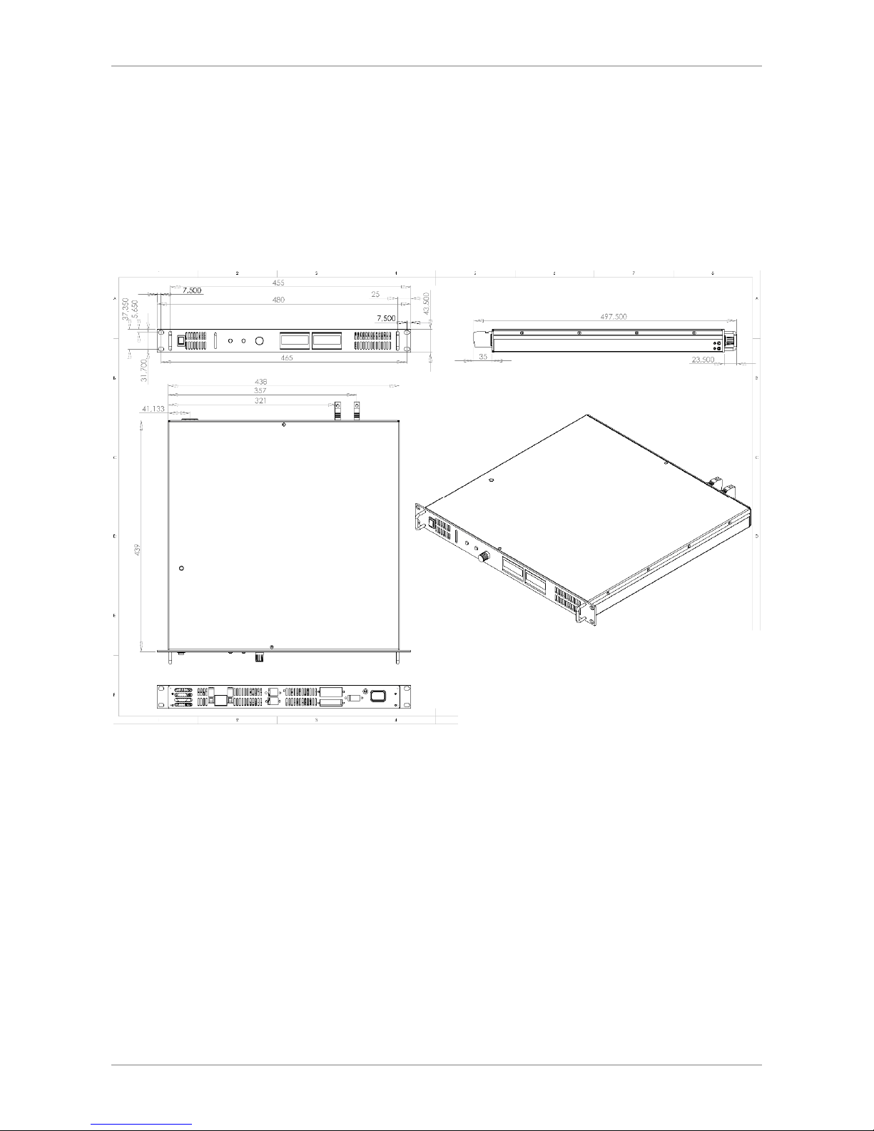
T
ECHNICAL DRAWING
Page 11
Important Safety Instructions
IMPORTANT SAFETY INSTRUCTIONS
Ple ase re ad t h is ma nu a l tho rou ghl y bef or e putt ing the de vic e
int o ope rat ion . Pay re g ar d to th e f o ll o wi ng sa f et y in str uct ion s
and ke ep thi s m anu al nea rb y fo r f ut u re pu rpo se.
This operating manual is based on the state of technology at the time of printing. However, it is possible that despite
regular control and correction, the present document contains printing errors or deficiencies. EPS Stromversorgung
GmbH assumes no liability for any technical, printing or translational errors within this manual.
I
NITIAL OPERATION
U
NPACKING
Please make sure that the shipping carton and the packaging is free of damage. If external damage is found, it is
important to record the type of damage. Please keep the original packaging to ensure the device is adequately
protected in case it needs to be transported in the future or claims for compensation need to be asserted.
S
ETTING UP
To avoid electric shocks and product failure, the device should be installed in a temperature and humidity controlled
indoor environment. The ambient temperature must not exceed 50 °C. The device must never be exposed to liquids or
extreme humidity.
V
ISUAL INSPECTION
The unit must be examined immediately for defects or damages in transit. Damages caused during transport may be
loose or broken control knobs and bent or broken connectors. Do not use the device if any physical damage is
apparent. Please inform the carriers and a representative of EPS Stromversorgung immediately.
M
AINS OPERATION
Make sure to verify the model number and voltage stated on the nameplate. Damages due to wrong power feed are
not covered by guarantee conditions.
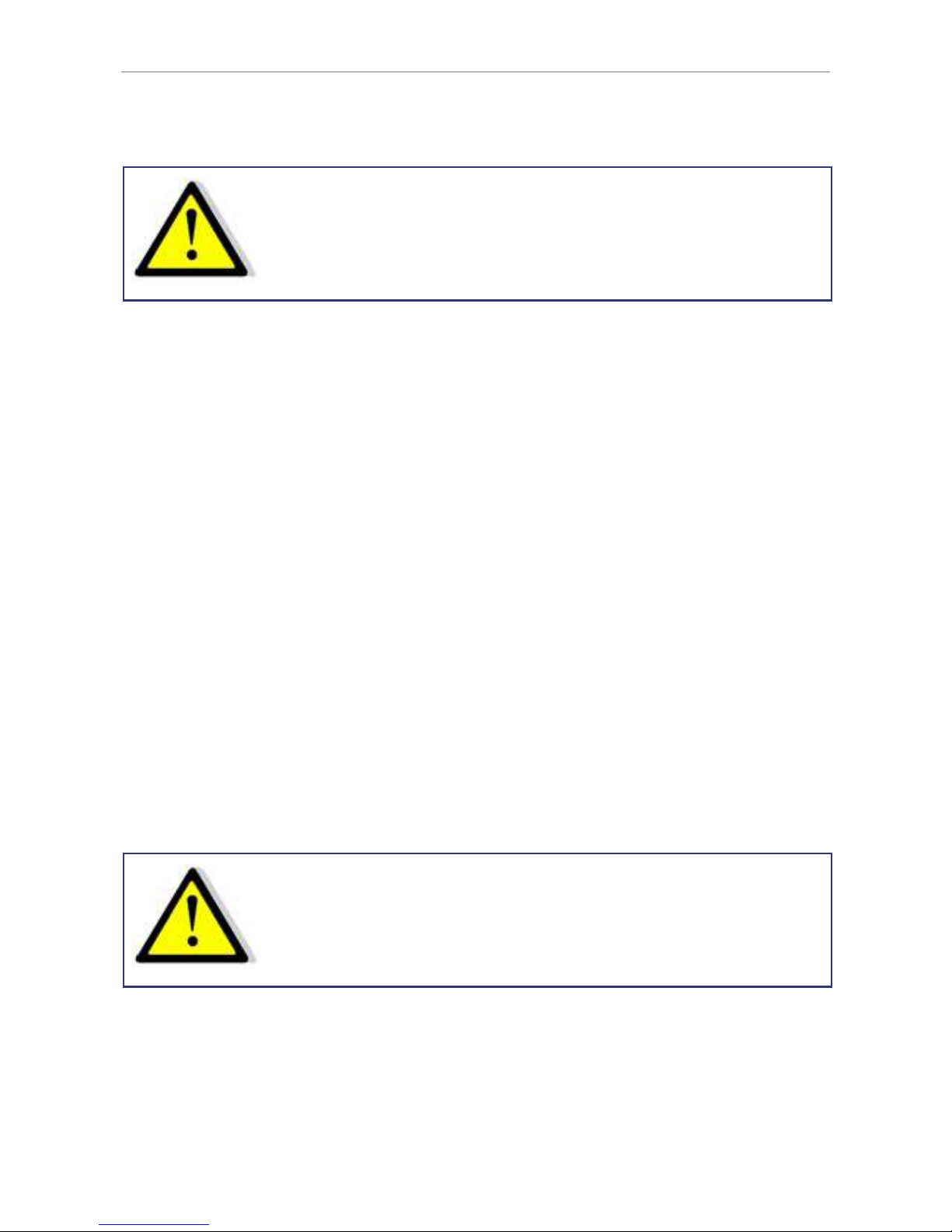
The u nit m u st o n ly b e ope rat ed wh en co nn e ct e d dir ect ly to t he
mai ns. To av oid da ma g e, do not c o nn e ct th e u nit to
iso lat ing tra nsf or mer s, a uto -tr ans f or mer s, m ag n eti c c u rr ent
lim ite rs or sim ila r d evi ces .
Page 12
Functional Description
8
FUNCTIONAL DESCRIPTION
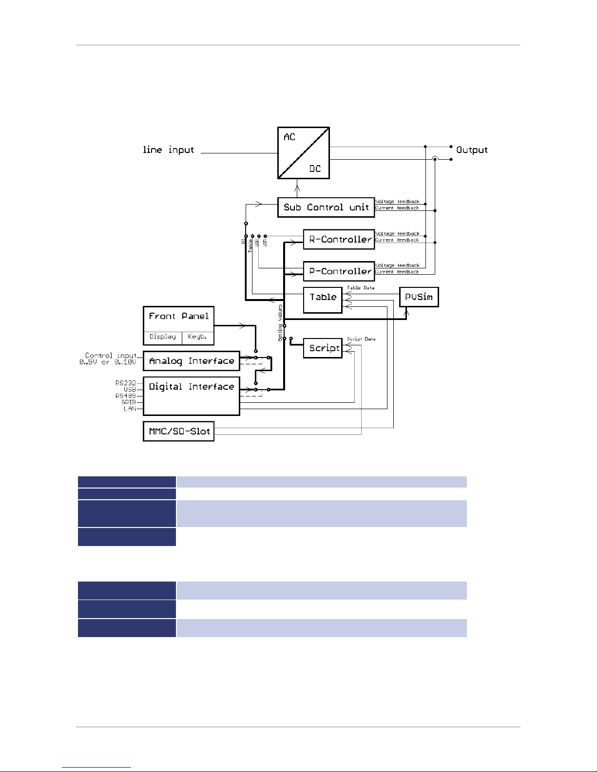
The following block diagram gives information about the various adjustment options.
Basically, four different operation modes are available:
UI mode
Unit is operated with current and voltage limitation.
UIP mode
Unit is operated with current, voltage and power limitation.
UIR mode
Unit is operated with current, voltage and power limitation. Additionally, the set value for
voltage is calculated by means of the present output current to simulate an internal
resistance.
Table mode
Set
values for current and voltage are saved in a table. Therefore, UI characteristics can be
easily adjusted.
There are three different ways to program the table:
PV
sim
mode
The UI characteristic of a solar generator is calculated with the Uo, Ik, Umpp and
Impp
parameters and then written to the table.
Memory card
The table can be programmed using a script from a memory card.
A script is a simple text file ( Script Control).
Digital interface
The table can be programmed using the digital interface (
Universal Interface
,
WAVE
Command bzw. DAT Command).
Page 13
General Settings
The adjustment of set points and the selection of an operation mode are performed via console ( Front Panel
Operation), interface ( Universal Interface) or analog/digital IO ( Ext. Control: AI-Interface).
In order of priority, commands which have been sent by interface come first, by analog/digital-IO come second and by
keyboard come third. For example, if the interface specifies the set point, the corresponding values will be sent to the
output, irrespective of other settings.
Another easy way to automate functions is offered by script control ( Script Control). A list of commands is saved to
the script memory and enables the user to change the chronological sequence of certain settings. The script memory
can be programmed via memory card or digital interface.
Measurement values of the latest output data are permanently available at all interfaces. Therefore, the present
output voltage can be read from the display or via digital interface, while the control of the unit is carried out via
analog/digital IO.
GENERAL SETTINGS
F
RONT PANEL DESCRIPTION
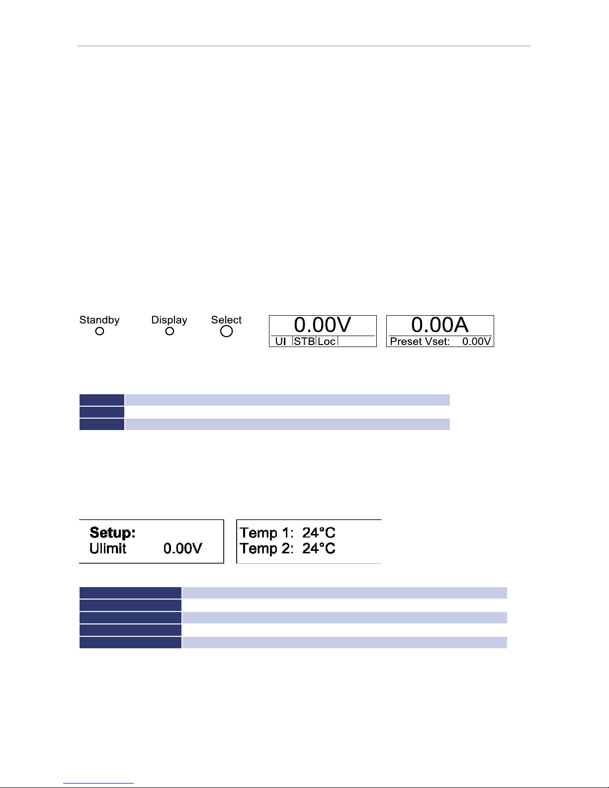
The picture above shows a schematic view on the front panel of the EPS/MP. There are 3 buttons to control the unit.
Basic functions of the control buttons:
Standby
release or lock the output, quit OVP
Display
short press: change displayed information, long press: change between main menu and setup menu
Select
press: change selected menu point, rotate: change selected value
C
ONFIGURATION
The configuration menu can be accessed by holding the button
Display
for at least 1 second. This opens a menu
where general settings of the unit can be changed. To browse through the different options, the button
Select
must
be pushed. To change a setting the button
Select
must be rotated.
Setup options:
U
limit
0 V-V
max
; set maximum output voltage which is selectable at the front panel
I
limit
0 V-V
max
; set maximum output current which is selectable at the front panel
OVP
0 V- 1.2 x V
max
; set over voltage protection activation value
AI-Mode
5 V/10 V; select the AI-control voltage range
Remember Last Setting
ON/OFF; activate or deactivate the settings memory after a power down the unit
The displayed temperature is the temperature of the heat sinks. Temperature 1 is the temperature of the PFC heat
sink and temperature 2 is the temperature of the power unit heat sink.
Page 14
Voltage Settings
10
C
ONTRAST
After the unit has been switched on, the display shows the EPS logo. The contrast of the display can be adjusted by
using the rotary pulse encoder
Select
. Afterwards, the contrast settings will be saved automatically.
VOLTAGE SETTINGS
U
LIMIT
AND
I
LIMIT
U
limit
limits the maximum output voltage. The output voltage is limited to the selected value, irrespective of the values
that have been set at the front panel or at one of the interfaces. The adjustment range is 0 V up to the maximum
rated voltage of the device.
I
limit
limits the maximum output current. The output current is limited to the selected value, irrespective of the values
that have been set at the front panel or at one of the interfaces. The adjustment range is 0 A up to the maximum
rated current of the device.
These settings can only be changed at the display and they apply to all interfaces.
OVP (O
VER VOLTAGE PROTECTION
)
The output is shut immediately if the output voltage exceeds the selected value. The display indicates this status with
the word ‚OVP‘. To reset this error, push the button
Standby
. The OVP value applies to the front panel operation.
There may apply different values for the AI-interface and the digital interface. The digital interface is initialized with
the value which has been adjusted on the front panel. The adjustment range is 0 V up to the maximum rated voltage
of the device + 20 %.
AI-T
YPE
This feature adjusts the voltage levels of analog input signals and analog output signals. Selectable ranges are 0-5 V
and 0-10 V.
R
EMEMBER LAST SETTING
If this option is activated (‚On‘), selected parameters will be kept after a blackout. If this option is deactivated (‚Off’),
standard setting (0V/0A/UI-Mode) will be loaded after supply voltage is enabled.
I
NTERFACE PARAMETER (OPTION
)
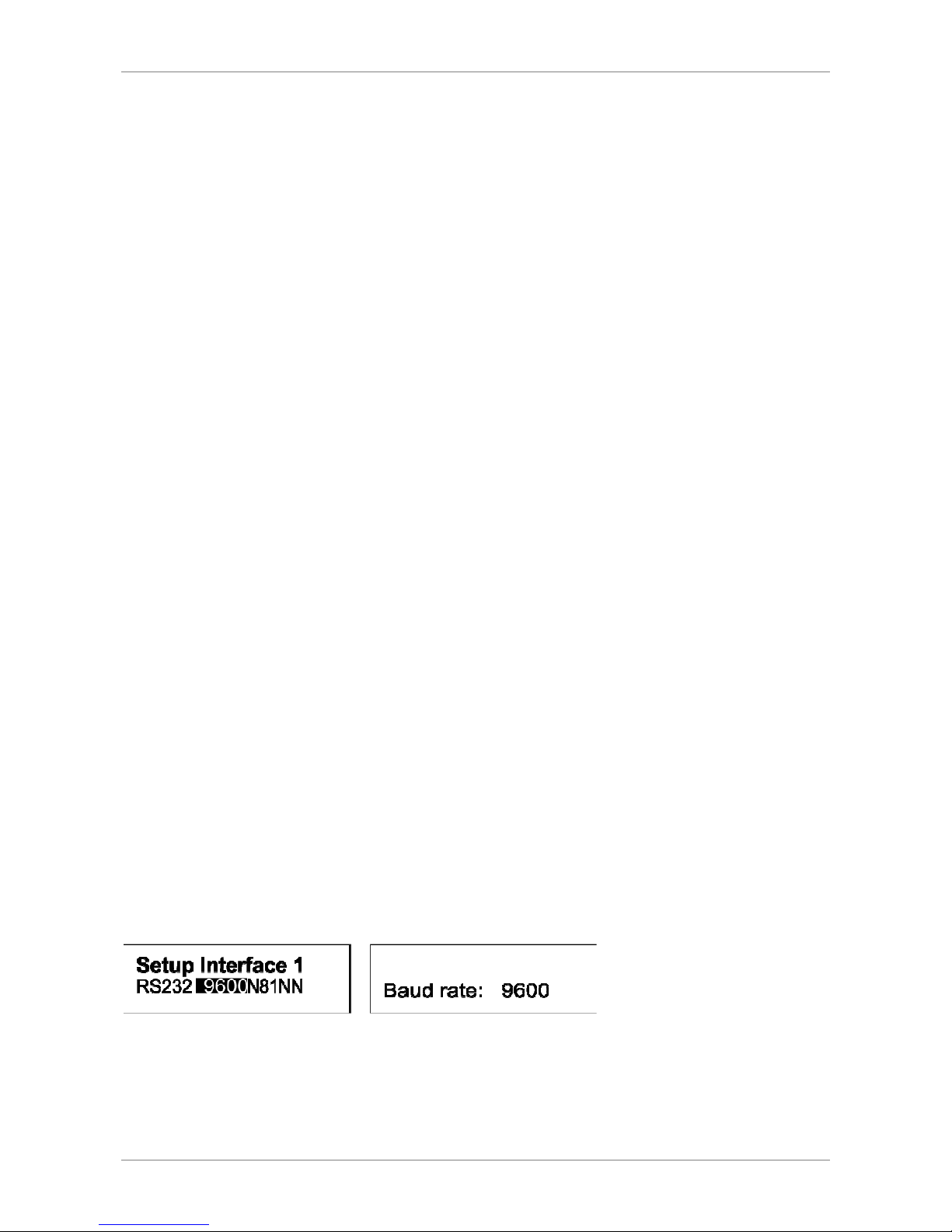
The display shows all available digital interfaces and their changeable parameters. To see interface parameters, push
the button
Display
for 1 second. Push this button again to see the first interface and its changeable parameters,
which can be selected by pushing the rotary pulse encoder and changed by turning the rotary pulse encoder (function
of the parameters Universal Interface).
Page 15
Front Panel Operation
FRONT PANEL OPERATION
D
ISPLAY AND SETTINGS
Current measurement values (Display)
In normal mode, pushing the button
Display
switches between five different overview screens.
Main display
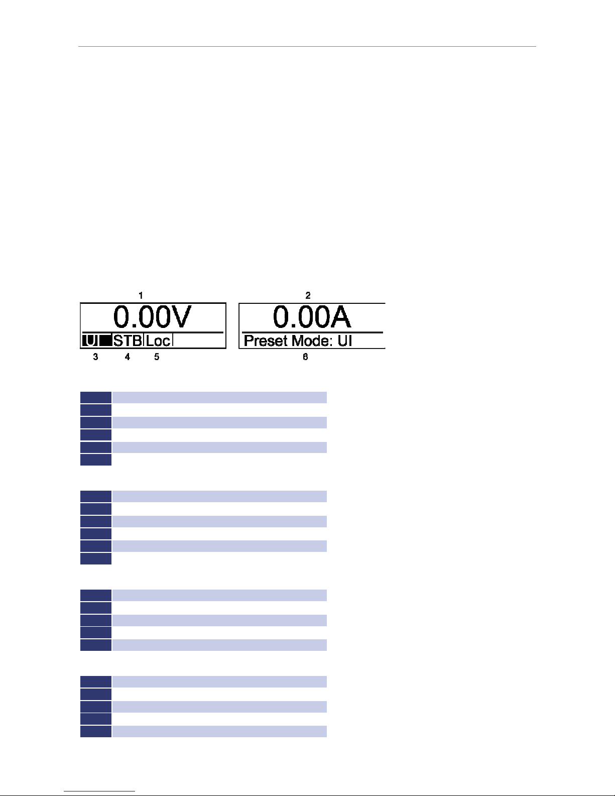
The main display shows current measure and set values. The display is divided in two separate displays. After enabling
the unit, the measured values for output voltage and putput current (position 1 and 2) are displayed. On the right
display (position 6) the actual set value (Preset V
set
) is shown. To change this value, the rotary pulse encoder
Display
must be turned. Pushing the button
Select
, toggles through the next set parameters (in UI mode it will be output
current). To open the mode select menu (left display, position 3) where different operation modes are available, the
button
Select
must be pushed again.
Selectable parameters according to operation mode:
U
Output voltage
I
Ouput current
P
Output power (UIP mode only UIP mode)
Ri
Internal resistance (UIR mode only UIR mode)
U
mpp
MPP voltage (PV
sim
mode only PVsim mode)
I
mpp
MPP current (PV
sim
mode only PVsim mode)
Selectable options in current control mode (left display, position 5):
Loc
Front panel operation
Scr
Memory card operation
AI
Analog interface operation
Rem
Interface operation
LLO
Interface operation , Front panel operation locked
Dis
Unit locked via interlock input (option)
Available modes for operating status of the unit (left display, position 4):
STB
Standby mode
CV
Voltage limitation mode
C
Current limitation mode
CP
Power limitation mode
OVP
Deactivation of the unit by over voltage protection
Available operation modes of the unit (left display, position 3):
UI
Voltage and current limitation
UIP
Voltage, current and power limitation
UIR
Voltage and current limitation, simulated internal resistance
PV
sim
Simulation of a photovoltaic characteristic
User
Simulation of a user-defined characteristic
Page 16
Front Panel Operation
12
O
PERATING MODES
Main display overview
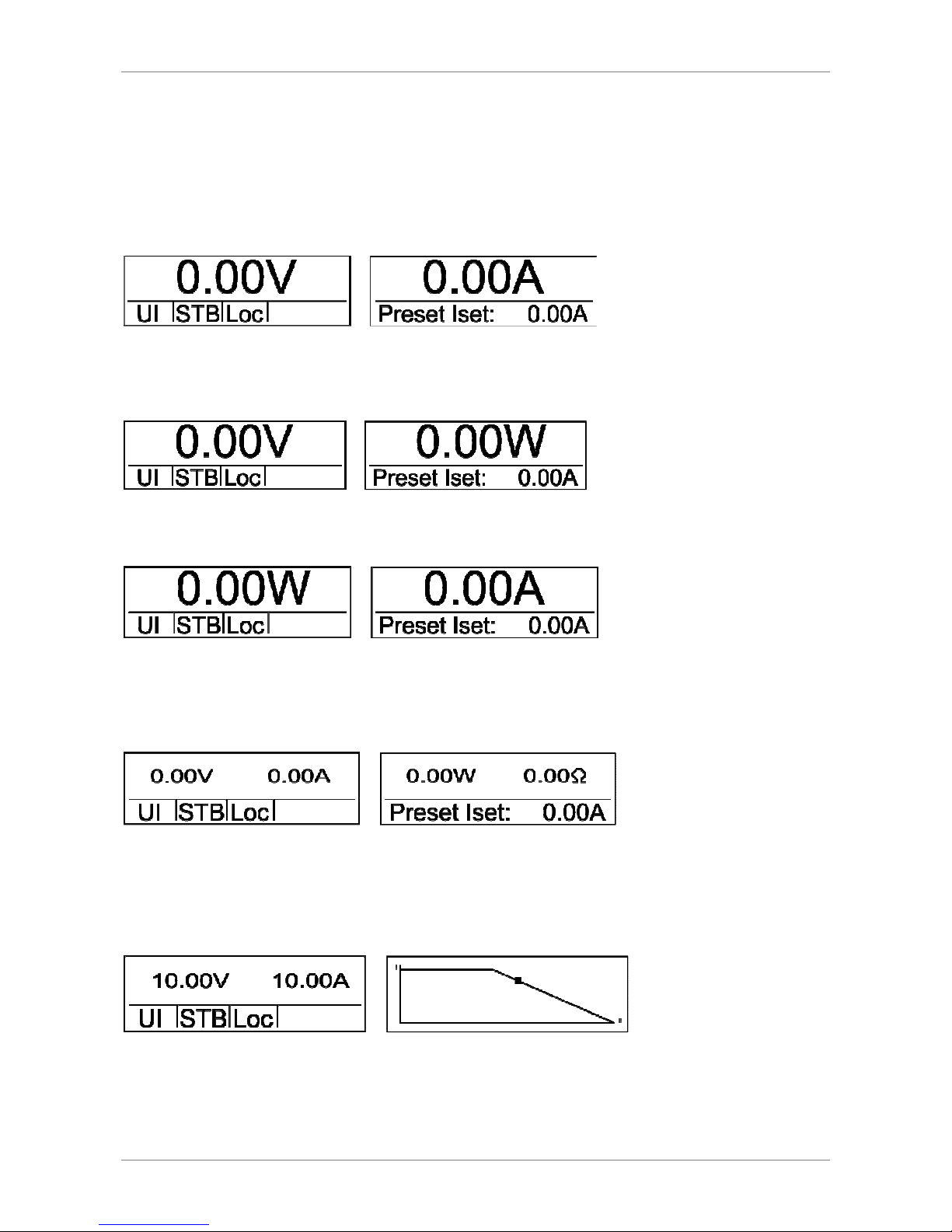
Main display 1
After power up, the display shows the actual output voltage and output current.
Main display 2
After pushing the button
Select
once, actual output voltage and output power are shown on the display.
Main display 3
After pushing the button
Select
twice, actual output power and output current are shown on the display.
Main display 4
After pushing the button
Select
thrice, actual output voltage and output current are shown on the left display and
actual output power (P = U * I) and load resistor (R = V ÷ C) are shown on the right display. The values for power and
resistor will be calculated from the actual values of the output voltage and the output current.
Main display 5/diagram screen
After pushing the button
Select
four times, actual output voltage and output current are shown on the left display.
The output characteristic of the power supply is shown on the right display. The X-axis shows the output voltage and
the Y-axis shows the output current.
The picture above shows the UIR mode of the power supply. The dot marks the actual operation point of the unit. The
diagram is always scaled for the maximum allowed output current (this value can be set in the setup menu (I
limit
)) and
the maximum allowed output voltage (this value can be set in the setup menu (U
limit
)).
Page 17

Front Panel Operation
Operating Mode description
UI Mode
In UI mode, the set values for voltage and current are transferred directly to the switch mode regulator. There is no
additional digital control.
UIP Mode
In UIP mode, the set values for voltage and current are transferred directly to the switch mode regulator. If the output
current exceeds the previously adjusted limit value, the current set point will be regulated.
UIR Mode
In UIR mode, the voltage set point is regulated in a way that a power supply unit with (adjustable) internal resistance
is simulated. The set value for current limiting is transferred directly to the switch mode regulator.
PV
sim
Mode
In PV
sim
mode, the diagram of a PV generator is simulated. Given values are open-circuit voltage Uo, short-circuit
current Ik, as well as the amounts of voltage and current by which the PV generator delivers the maximum power
(U
mpp
, I
mpp
). Parameters can be found in the specification sheet of the simulated PV generator.
Values for U
mpp
may be in a range from 0.6 to 0.95 * U.
Values for I
mpp
may be in a range from 0.6 to 0.95 * I.
Script Mode
In script mode, the unit is controlled by memory card. The display status ‚Mode‘ shows the present operating mode
‚UI‘. The lower right corner of the display shows the word ‚Scr‘, which indicates that script operation was selected. If
there is no memory card in the slot, this option cannot be selected. For detailed information about memory card
control and about how to build up a script, see Script Control.
Page 18

Universal interface (Option)
14
UNIVERSAL INTERFACE (OPTION)
All interfaces of the digital interface are equal. There is no shift between the interfaces. For example, the first
command can be issued via the IEEE interface while the second command can be issued via the RS232 interface. The
return values will be sent from that interface the command was issued from.
C
OMMANDS
Communication is based on an ASCII protocol. The following chapters describe how to write a command and give an
overview over the commands.
Format
A command consists of the command word, a parameter (if necessary) and a terminator. The character for the
terminator is Carriage Return
<CR>
or Line Feed
<LF>
.
Character ASCII Dec value Hex value
Carriage Return
<CR> 13 0d
Line Fee
<LF> 10 0a
If the command contains a <DEL> or <ESC> character, it will not be processed. Therefore, a command can be cancelled
while entering. Though, a terminator (
<CR>
or
<LF>
) is necessary.
Character ASCII Dec value Hex value
Escape
<ESC> 27 1b
Delete
<DEL> 127 7f
Commands are not case sensitive and may be mixed up. Therefore, the effect of the following commands is the same:
GTL, Gtl, gTL. Decimal places are optional and separated by a full stop ‘.‘ . The number of decimal places is not limited.
Therefore, the effect of the following commands is the same: UA,10, UA,10.0, UA,10.000000000, UA,0010,
UA,010.0000
The number of decimal places to be analyzed depends on parameter and unit type. It corresponds to the number of
decimal places, a command without a parameter would return. As a rule, decimal places are analyzed until a
resolution of 0.1% is reached.
Example: Evaluation of decimal places
EPS/MP with 600 V, 25 A
600 V * 0.1 % = 0.6 V one decimal place
25 A * 0.1 % = 0.025 A three decimal places
Optional, after a numerical value, a letter may be added to indicate the unit. However, this letter will not be analyzed.
Example: Attached letter as unit
UA,10.0 V Resets output voltage to 10 V
UA,10.0 m Caution! The ‚m‘ will not be evaluated, output voltage here is also 10 V
Example: A valid command with corresponding hex values
U A , 1 0 . 2 <CR>
55 h 41 h 2 ch 31 h 30 h 2 eh 32 h 0 dh
Example: Adjustment of output voltage 10 V/5 A (full command sequence)
OVP,100 adjusts OVP to 100 V
UA,10 adjusts output voltage to 10 V
IA,5 current limiting 5 A
SB,R output enabled
Page 19
Universal interface (Option)
Instruction Set
The IEEE-488.2 standard demands several basic commands. Some commands may occur twice for compatibility
reasons (once in the EPS version and once in the (old) IEEE-488.2 version). The following syntax is used to describe the
commands:
[] Square brackets optional parameter
<> Angle bracket numerical value
{} Curly bracket selection list
| Vertical line separator within selection list
Example
GTR[,{0|1|2}] means that the command GTR can be used with or without parameters. If a parameter exists, it has to be 1, 2 or 3. Valid
commands are: GTR GTR,1 GTR,2 GTR,3
IA[,<imax>] means that the command IA can be used either with or without parameters. If a parameter exists, it has to be a numerical
value.
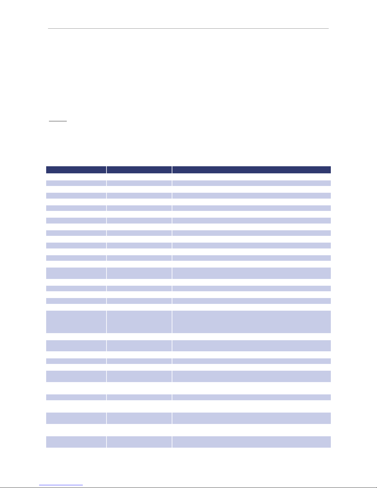
Quick view of commands
Command Description Result
CLS* or CLS
Clear Status
Deletes the status byte
DAT,<U>,<I>
DIP Data for user
-
defined characteristic
DCL Device Clear
Initialization data reset
GTL Go To Local
Activates front panel operation
GTR[,{0|1|2}]
Go To Remote
Activates digital interface
operation
IA[,<imax>]
Set I
max
Adjusts current limiting
ID or *IDN?
Identification
Displays identification string
IMPP[,<impp>]
Set I
mpp
Adjusts MPP current during PVsim mode.
LLO Local Lockout
Deactivates LOCAL button
LIMI Limit I
a
Reads maximum
adjustable current limitation
LIMP Limit P
a
Reads maximum unit output.
LIMR Limit R
Reads adjustable range for R
i
within UIR mode.
LIMRMAX
Limit R
max
Reads maximum adjustable range for R
i
within UIR mode.
LIMRMIN
Limit R
min
Reads minimum adjustable
range for R
i
within UIR mode.
LIMU Limit U
a
Reads maximum adjustable voltage limitation
MODE[,{UI|UIP|UIR|PVSIM|
USER|Skript}]
Set Mode Selects operation mode
MU[,<Nr>]
Measure U
a
Measures present output voltage
MI[,<Nr>]
Measure I
a
Measures present
output current
*OPT? Optional Identification Query
Displays units current hardware/software version
OVP[,<U
ovp
>] Overvoltage Protection
Adjusts over voltage protection
PA[,<P
limit
>] Set P
max
Adjusts power limitation
PCx[,<baud>,<parity>,
<data bits>,<stop bits>,
<handshake>,<echo>,
<timeout>]
Program
Communication
Adjusts the interfaces
RA[,<R
i
>] Set Ri
Adjusts internal resistance
REGLER[,<Nr>,<Kp>,<Ki>,
<Kd>]
Controller Parameters Adjusts controller parameters for UIP, UIR and PVsim mode
RI or
*RST Reset Instrument
Resets hardware (no return value)
SB[,{S|R|1|0}]
Standby
Enables/blocks the output
SCR[,<CMD>[,<value>]]
Load Script
Programming of script memory
SS or *PDU Save Setup
Saves previously made channel and interface parameter
adjustments (no return
value)
STATUS Status
Query of the units status (return values in binary format) (also see following
table)
STB or *STB?
Interface Status
UA[,<ua>] Set Ua
Adjusts output voltage (if there are no parameters, present set point is
displayed)
UMPP[,<umpp>] Set U
mpp
Adjusts MPP voltage in PV
sim
mode (if there are no parameters, present set point
is displayed)
WAVE End Userwave Data
Ends transfer of user
-
defined output characteristic (gradual interpolation of
intermediate values)
WAVELIN End Userwave Data
Ends transfer of user
-
defined output characteristic (linear interpolation of
intermediate values)
WAVERESET,<Um>,<Im>
Start Userwave Data
Starts transfer of user
-
defined output characteristic
Page 20

Universal interface (Option)
16
Detailed description of commands
CLS* or CLS - Clear Status
This command deletes the status byte. It affects only the status byte of the interface, the command was sent from. No
return value. For detailed description of the status byte see the different interface chapters.
DAT,<U>,<I> - Data
Data for a user-defined characteristic. No return value. For detailed description of this command see Wavereset.
DCL - Device Clear
This command resets the initialization data. No return value.
Caution: Interface parameters are also reset!
GTL - Go To Local
This command activates front panel operation. If ‚Local Lockout‘ (LLO) was activated before, it will also be reset. No
return value.
GTR[,{0|1|2}] - Go To Remote
This command activates digital interface operation. The optional parameter affects the future behavior of the unit
after switch on. Setting is saved permanently. No return value.
Optional parameter 0 = Deactivates automatic remote operation
The command GTR must be entered to activate the unit’s remote operation mode. This mode is useful if the unit shall be operated
manually and at the same time, measurement values shall be read out via the digital interface.
Optional parameter 1 = Activates remote operation on first addressing
Unit switches to remote operation when receiving a command via digital interface. The only exception is the GTL command, which
switches the unit to local mode.
Optional parameter 2 = Activates remote operation immediately after switch on
After the unit was switched on, remote mode is immediately activated. Front panel operation is deactivated.
IA[,<imax>] - Set I
max
This command adjusts current limiting. Entering the command without parameters displays the set value. If the set
value is higher than the maximum current of the unit, the range-error-bit within the ESR register of the interface is set.
The present set value remains unchanged. If the set value is higher than the I
limit
value, which was adjusted by the
user’s settings, but lower than the maximum current of the unit, the current is limited to the I
limit
value. No error
message.
Example: 300 A unit, I
limit
adjusted to 200 A via configuration menu
GTR Remote operation
OVP,200 Over voltage protection 200 V
UA,10 Output voltage 10 V
IA,100 Output current 100 A
SB,R Output open
IA,400 Output current 400 A, this command is ignored, because the current is higher than the maximum current of the device.
„Rangeerror“ is set within the status byte.
IA,250 Output current 250 A, since the output current was limited to 200 A via configuration menu, current limiting is set to 200
A. Error bit is not set.
IA Query of the adjusted current.
IA,200.0A Unit answers: I
limit
= 200 A
In master/slave mode, the current of a programmed device is adjusted. Connected in parallel, the total current is n x IA.
Example:
In M/S mode, 3 devices are connected parallel. IA,10 programs an output current of 10 A. All connected devices are set to 10 A. Since 3
devices have been connected parallel, the total current is 3 x 10A = 30A.
ID or IDN? - Identification
This command displays the identification string. Return value: <ID-String>.
Page 21

Universal interface (Option)
IMPP[,<impp>] - Set I
mpp
This command adjusts the MPP current for PV
sim
mode. Entering the command without parameters displays the set
value. If the set value is higher than the maximum current of the unit, the range-error-bit within the ESR register of
the interface is set. The present set value remains unchanged. If the set value is higher than the I
limit
value, which was
adjusted by the user’s settings, but lower than the maximum current of the unit, the current is limited to the I
limit
value. No error message follows.
Example:
GTR Remote operation
OVP,200 Over voltage protection
UA,50.5 Open circuit voltage of a 50.5 V simulated PV generator
IA,10 Short circuit current of a simulated 10 A PV generator
UMPP,40.4 MPP voltage of a simulated 40.4 V PV generator
IMPP,8.2 MPP current of a simulated 8.2 A PV generator
MODE,PVSIM Activates PV simulation mode
SB,R Output open
In master/slave mode, the current of a programmed device is adjusted. In parallel connection the total current is n x IA.
LIMI - Limit I
a
With this command the user can read the maximum adjustable current limiting.
Example: 300A unit, I
limit
was adjusted to 200 A via configuration menu
LIMI Query of maximum adjustable current
LIMI,200.0A Unit answers: I
limit
= 200 A
LIMP - Limit Pa
With this command the user can read the unit’s maximum output.
Example: 10 kW unit
LIMP Query of units output
LIMP,10000 Unit answers: 10 kW
LIMR - Limit R
With this command the user can read the adjustable range for Ri within UIR mode.
Example:
LIMR Query of adjustable internal resistance
LIMR,0.015R,1.00R Unit answers: 15 mOhm up to 1 Ohm
LIMRMAX - Limit R
max
With this command the user can read the maximum adjustable range for Ri within UIR mode.
Example:
LIMRMAX Query of maximum adjustable internal resistance
LIMRMAX,1.000R Unit answers: 1 Ohm
LIMRMIN - Limit R
min
With this command the user can read the minimum adjustable range for Ri within UIR mode.
Example:
LIMRMIN Query of minimum adjustable internal resistance
LIMRMIN,0.015R Unit answers: 15 mOhm
Page 22

Universal interface (Option)
18
LIMU - Limit Ua
Reads maximum adjustable voltage limitation. This command requests the previously defined maximum output
voltage.
Example: 300 V unit was adjusted to 200 V via configuration menu
LIMU Query of maximum adjustable current
LIMU,200.0V Unit answers: U
limit
= 200 V
LLO - Local Lockout
This command deactivates the
Local
button. Unit cannot be switched to local mode by holding the button
Standby
.
No return value.
MI[,<Nr>] - Measure I
a
This command measures the present output current.
Example:
GTR Remote operation
OVP,200 Over voltage protection 200 V
UA,10 Output voltage 10 V
IA,1 Output current 1 A
SB,R Output open
MI Measures present output current
MI,0.567A Unit answers: 567 mA
In master/slave mode with parallel connection the total current of all connected devices is displayed. Using the
parameter <Nr> will show the value of each connected device. Numbering starts with 0.
Example:
MI,2 displays the measured output current at the bus of device number 3.
MODE[,{UI|UIP|UIR|PVSIM|USER|Skript|0|1|2|3|4|5}] - Set Mode
This command selects the operation mode. Entering the command without parameter displays the presently selected
operation mode. Entering the command with parameter activates the operation mode. Alternatively, the operation
mode can be indicated as number.
The following table shows the different settings:
Command Function
MODE,UI
MODE,0
UI mode is activated
MODE,UIP
MODE,1
UIP mode is activated
MODE,UIR
MODE,2
UIR mode is activated
MODE,PVSIM
MODE,3
PV
sim
mode is activated
MODE,USER
MODE,4
User-defined UI characteristic is activated. The characteristic is defined with the
commands
DAT, WAVE, WAVELIN
and
WAVERESET
.
MODE,SKRIPT
MODE,5
Script mode is activated. The script is read from the memory card or loaded after
the command SCR has been entered.
Page 23

Universal interface (Option)
MU[,<Nr>] - Measure U
a
This command shows the measurement value of the present output voltage.
Example:
GTR Remote operation mode
OVP,200 Over voltage protection 200 V
UA,10 Output voltage 10 V
IA,1 Output current 1 A
SB,R Output open
MU Measures present output voltage
MU,10.0V Unit answers: 10 V
In master/slave mode with serial connection the total current of all connected devices is displayed. Using the
parameter <Nr> will show the value of each connected device. Numbering starts with 0.
Example:
MU,1 displays the measured output voltage at the bus of device number 2.
*OPT? - Optional Identification Query
This command does an optional identification query, which means it displays the software version.
Example:
*OPT? Query of version number
08.06.2012 V42 Unit answers: Version 42 vom 08.06.2012
OVP[,<U
ovp
>] - Over Voltage Protection
This command adjusts the over voltage protection. Entering the command without parameter displays the present set
point. If the set point is higher than a maximum of 1.2 x voltage of the unit, the range error bit within the ESR register
of the interface is set. The present set point remains unchanged.
Example:
GTR Remote operation mode
OVP,200 Over voltage protection 200 V
UA,100 Output voltage 100 V
IA,10 Output current 10 A
SB,R Output open
PA[,<P
limit
>] - Set P
limit
This command adjusts the power limitation for UIP mode. Entering the command without parameter displays the
present set point. If the set point is higher than the maximum power of the unit, the range error bit within the ESR
register of the interface is set. The present set point remains unchanged.
Example:
GTR Remote operation mode
MODE,UIP UIP mode activated
OVP,200 Over voltage protection 200 V
UA,100 Output voltage 100 V
IA,10 Output current 10 A
PA,500 Power limitation 500 W
SB,R Output open
In master/slave mode the power of a programmed device is adjusted. Total output is n x PA.
Example:
2 devices are in M/S mode. The command PA,100 sets the power output to 100 W. Both connected device are adjusted to 100 W. The
total output is 2 x 100 W = 200 W.
Page 24

Universal interface (Option)
20
PCx[,<baud>,<parity>,<data bits>,<stop bits>,<handshake>,<echo>,<timeout>] - Program Communication
This command adjusts the interfaces. The EPS/MP has a maximum of 3 digital interfaces (x = 1, 2 or 3). The
corresponding commands are
PC1, PC2
or
PC3
. Type and number of parameters depend on the type of interface.
Currently there are no settings available for GPIB and LAN. Entering the command without parameter displays present
interface parameters.
Parameter Function
<baud>
Baud rate in bps
<parity>
Data parity
O = Odd = Uneven parity
E = Even = Even parity
N = None = No parity bit
<data
bits> Number of data bits
<stop bits>
Number of stop bits
<handshake>
Handshake
H = Hardware
S = Software
N = None (no handshake)
<echo>
Character echo
E = Echo = echo on
N = None = echo off
<timeout>
Timeout in ms when switching between sending and
receiving (RS485 only)
Allowed parameters for RS232 interface:
PCx,<baud>,<parity>,<data bits>,<stop bits>,<handshake>,<echo>
Parameter Function
Baud: 1200, 2400, 4800, 9600, 14400, 19200, 38400, 57600, 62500, 115200
Parity: O, E, N
Data bits:
7, 8
Stop bits
1, 2
Handshake:
H, S, N
Echo: E, N
Allowed parameters for USB interface:
PCx,<baud>,<parity>,<data bits>,<stop bits>,<handshake>,<echo>
Parameter Function
Baud: 1200, 2400, 4800, 9600, 14400, 19200, 38400, 57600, 62500, 115200
Parity: O,
E, N
Data bits:
7, 8
Stop bits
1, 2
Handshake:
H, S, N
Echo: E, N
Note: The USB interface of the PC is controlled like a virtual COM port and therefore the parameters correspond to those of the RS232
interface.
Allowed parameters for RS485 interface:
PCx,<baud>,<parity>,<data bits>,<stop bits>,<timeout>
Parameter Function
Baud: 1200, 2400, 4800, 9600, 14400, 19200, 38400, 57600, 62500, 115200
Parity: O, E, N
Data bits:
7, 8
Stop bits
1, 2
Timeout:
0…100
If the interface parameters must be changed permanently, the data has to be saved after the
PCx
command with the
command
<SS>
. No return value.
Page 25

Universal interface (Option)
Example:
PC1 Query of first interface parameters
PC1,RS232,9600,N,8,2,N,E Unit answers: PC1 is a RS232 interface, 9600 bauds, 8 data bits, 2 stop bits, no handshake, no
parity, echo on.
PC1,115200,N,8,2,N,E Adjust baud rate to 115200 baud.
The new baud rate is active immediately after the command has been sent!
PC2 Query of second interface parameters
PC2,RS485,9600,N,8,1,1 Unit answers: PC2 is a RS485 interface, 9600 bauds, 8 data bits, 1 stop bit.
Timeout when switching between receiving and sending is 1 ms.
PC2,9600,N,8,1,50 Increase timeout to 50ms.
PC3 Query of third interface parameters
PC3, EMPTY Unit answers: Interface 3 is not available in this unit.
SS Save settings.
RA[,<Ri>] - Set Ri
This command adjusts the internal resistance for UIR mode. Entering the command without parameters displays the
present set point. If the set point is out of adjustment range the range error bit of the interface is set in the ESR
register. The present set point remains unchanged. Adjustment range can be requested with the commands
LIMRMAX
and
LIMRMIN
.
Example:
GTR Remote operation mode
MODE,UIR UIR mode activated
OVP,200 Over voltage protection 200 V
UA,100 Output voltage 100 V
IA,10 Output current 10 A
RA,0.1 Internal resistance 0,1 Ohm
SB,R Output open
REGLER[,<Nr>,<Kp>,<Ki>,<Kd>] – Controller Parameter
Settings for controller parameters in UIP, UIR and PV
sim
mode. Entering the command without parameters displays the
present settings as a table. The number of the parameter determines the parameter set which is to be adjusted.
0 Controller for UIP
1 Controller for UIR
2 Controller for PV
sim
The range of values for controller parameters is 0 - 30000. New settings can permanently be saved with the command
SS
. For a detailed description of the controller parameters see Controller.
Example:
REGLER Read present settings
Type P I D
P 10 20 5
Ri 20 20 2
Pv 10 5 5
Unit answers:
UIP Mode Kp = 20 Ki = 10 Kd = 5
UIR Mode Kp = 20 Ki = 20 Kd = 5
PV Mode Kp = 10 Ki = 5 Kd = 5
REGLER,0,10,10,5 New controller parameters for UIP mode
REGLER,1,22,18,5 New controller parameters for UIR mode
SS Save new settings
RI or *RST - Reset Instrument
The unit executes a hardware reset. No return value.
Page 26

Universal interface (Option)
22
SB[,{S|R|1|0}] - Standby
This command enables/disables the output. Entering the command without parameters displays the present standby
status. The commands
SB,S
and
SB,1
switch the unit to standby mode, the output is disabled. The commands
SB,R
and
SB,0
disable the standby mode, the output is enabled.
Example:
GTR Remote operation mode
OVP,200 Over voltage protection 200 V
UA,100 Output voltage 100 V
IA,10 Output current 10 A
SB,R Output is active
SB Retrieve standby status
SB,R Unit answers: output is active
SCR[,<CMD>[,<value>]] - Load Script
With this command the script memory can be programmed. The command
SCR
without parameters initializes the
programming procedure. The command
SCR
with parameters writes the commands into the script memory. The
order of the commands corresponds to the order of commands of the script. Script commands and their parameters
are described in the chapter Script Control.
Example:
GTR Remote operation mode
OVP,200 Over voltage protection 200 V
SCR Initialisation of script programming
SCR,U,12 1. script command: U = 12 V
SCR,I,15 2. script command: I = 15 A
SCR,UI 3. script command: mode UI
SCR,RUN 4. script command: activate output
SCR,LOOPCNT,10 5. start address loop
SCR,U,12 6. script command: U = 12 V
SCR,DELAY,8 7. script command: wait 8 ms
SCR,U,1 8. script command: U = 1 V
SCR,DELAY,1000 9. script command: wait 1 s
MODE,SKRIPT Activate script mode
SB,R Start script
SS or *PDU - Save Setup
Saves present unit parameters (interface parameter and controller parameter). No return value.
STATUS - Status
Query of device status. Return value in binary units. Function of the bits within the status byte:
Bit Function
D15
Number of units in M/S mode. If no other device is
connected, 1 is displayed, if two devices are connected to
the bus, 2 is displayed etc. If M/S mode was disabled via
configuration menu, 0 is displayed.
D14
D13
D12
D11 - reserved
-
D10 - reserved
-
D9 - reserved
-
D8 Limit mode, unit in power limitation mode
D7 Limit mode, unit in current limitation mode
D6 Local lockout (1 = LLO active, 0 = LLO not active)
D5 Local (1 = front panel
operation)
D4 Remote (1 = digital interface operation)
D3 - reserved
-
D2 - reserved
-
D1 Standby (1 = unit in standby mode)
D0 OVP (1 = shut down by over voltage protection)
Page 27

Universal interface (Option)
Example:
STATUS Status query
STATUS,0000000100010000 Unit answers: Remote operation mode, power limitation
UA[,<U
max
>] - Set U
max
This command adjusts the voltage limitation. Entering the command without parameters displays the present set
point. If the set point exceeds the maximum voltage of the unit, the range error bit within the ESR register of the
interface is set. The present set point remains unchanged. If the set point is higher than the selected value for U
limit
,
but lower than the unit’s maximum voltage, voltage limitation is restricted to U
limit
. There is no error message.
Example:
GTR Remote control operation
OVP,320 Over voltage protection 320 V
UA,100 Output voltage 100 V
IA,10 Output current 10 A
SB,R Output is active
UA,400 Output voltage 400 V. This command is ignored because the voltage is higher than the maximum voltage of the unit.
Range error is set within the status byte.
UA,250 Output voltage 250 V. Since the output voltage was limited to 200 V via configuration menu, voltage limitation is adjusted
to 200 V. An error bit is not set.
UA Query of adjusted voltage
UA,200.0V Unit answers: set point Ua = 200 V
In master/slave mode the voltage of the programmed device is set. In master/slave serial connection the total voltage
is n x UA.
Example:
3 devices are connected in series while in M/S mode. With UA,10 an output voltage of 10V is programmed. Therefore all connected
devices are adjusted to 10V. Since three devices are connected in series, the total voltage is 3 x 10 V = 30 V.
UMPP[,<Umpp>] - Set U
mpp
This command adjusts the MPP voltage for PV
sim
mode. Entering the command without parameters displays the
present set point. If the set point is higher than the maximum voltage of the unit, the range error bit within the ESR
register of the interface is set. The present set point remains unchanged. If the set point is higher than the U
limit
value
which was adjusted in the configuration menu, but lower than the maximum voltage of the unit, the voltage limitation
is restricted to U
limit
. There is no error message.
Example:
GTR Remote operation mode
OVP,200 Over voltage protection 200 V
UA,50.5 Open circuit voltage of a simulated PV generator 50.5 V
IA,10 Short-circuit current of a simulated PV generator 10 A
UMPP,40.4 MPP voltage of a simulated PV generator 40.4 V
IMPP,8.2 MPP current of a simulated PV generator 8.2 A
MODE,PVSIM Activate PV
sim
mode
SB,R Output active
In master/slave mode the MPP voltage of the programmed device is adjusted. When connected in series, the MPP
total voltage is n x UMPP.
WAVE - End Userwave Data
This command ends the transfer of a user defined output characteristic. Interpolation of interim values is layered. For
detailed information about the function of this command see Wavereset.
WAVELIN - End Userwave Data
This command ends the transfer of a user defined output characteristic. Interpolation of interim values is linear. For
detailed information about the function of this command see Wavereset.
Page 28

Universal interface (Option)
24
WAVERESET,<U
max
><I
max
> - Start Userwave Data
Starts the transfer of a user defined output characteristic. The parameters U
max
and I
max
define the maximum voltage
of the output characteristic. Afterwards, the fulcrums of the UI characteristic can be entered using the command
DAT
. The characteristic ends with the commands
WAVE
or
WAVELIN
.
Example:
GTR Remote operation mode
OVP,200 Over voltage protection 200 V
WAVERESET,100,10 Output characteristic with a maximum of 100 V and 10 A
DAT,90,1 Fulcrum 90 V, 1 A
DAT,50,5 Fulcrum 50 V, 5 A
DAT,10,9 Fulcrum 10 V, 9 A
WAVELIN End of characteristic, linear interpolation
MODE,USER Activates the created UI characteristic
SB,R Output active
For more information and examples of user defined characteristics see Wave, Wavelin and Programming of
characteristics (Script Operation).
Response String
The response string has the following format:
command comma value unit <CR> <LF>
The value is a floating point string with a ‘.‘ as delimiter.
Command Response Command Response
IA IA,12.34A
MU MU,10.0V
LIMU LIMU,500.0V
PA PA,12W
LIMI LIMI,30.00A
RA RA,0.015R
LIMP LIMP,15000W
UA UA,100.0V
LIMRMIN
LIMRMIN,0.015R
UMPP UMPP,90.2V
LIMRMAX
LIMRMAX,0.110R
IMPP IMPP,10.01A
LIMR LIMR,0.015R,0.110R
OVP OVP,600.0V
Example: Command as ASCII and HEX protocol
L I M U , 5 0 0 . 0 V
4C 49 4D 55 2C 35 30 30 2E 30 56 0D 0A
The digits after the decimal point correspond to the resolution of the unit.
Example
UA at a 600 V unit UA,123.4V
UA at a 50 V unit UA,23.44V
The digits before the decimal point depend on the present measurement value.
Example: 600 V unit
UA,10.4V
UA,220.3V
UA,1.1V
Example: 50 V unit
UA,1.23V
UA,10.47V
UA,0.01V
Page 29
Ext. Control: Computer
EXT. CONTROL: COMPUTER
GPIB
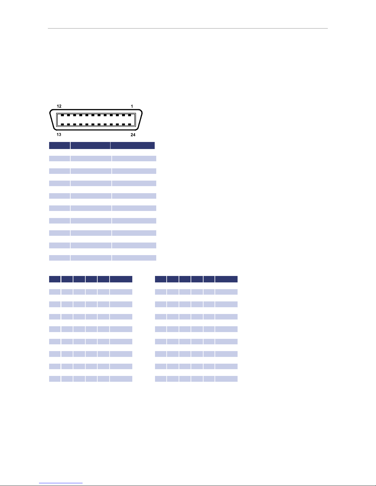
Connection is carried out with a 24pin Centronics connector. The device address is adjusted with the DIP switches S1S5. Here, S1 has the lowest priority and S5 the highest.
No Name Function
1 DIO1 Data line 1
2 DIO2 Data line 2
3 DIO3 Data line 3
4 DIO4 Data line 4
5 EOI End or Identify
6 DAV Data Valid
7 NRFD Not Ready For Data
8 NDAC No Data Accepted
9 IFC Interface Clear
10 SRQ Service Request
11 ATN Attention
12 SHIELD
Shield
13 DIO5 Data line 5
14 DIO6 Data line 6
15 DIO7 Data line 7
16 REN Remote Enable
18 - 23
GND Ground
24 SGND Signal Ground
Table: Device address
S1 S2 S3 S4 S5 Address S1 S2 S3 S4 S5 Address
Off Off Off Off Off 0
Off Off Off Off On 16
On Off Off Off Off 1 On
Off Off Off On 17
Off On Off Off Off 2
Off On Off Off On 18
On On Off Off Off 3 On On
Off Off On 19
Off Off On Off Off 4
Off Off On Off On 20
On Off On Off Off 5 On
Off On Off On 21
Off On On Off Off 6
Off On On Off On 22
On On On Off Off 7 On On On
Off On 23
Off Off Off On Off 8
Off Off Off On On 24
On Off Off On Off 9 On
Off Off On On 25
Off On Off On Off 10
Off On Off On On 26
On On Off On Off 11 On On
Off On On 27
Off Off On On Off 12
Off Off On On On 28
On Off On On Off 13 On
Off On On On 29
Off On On On Off 14
Off On On On On 30
On On On On Off 15 On On On On On 31
The device address is read in only when the unit is switched on. Changing the DIP switches while the unit is active will
not change the device address!
Table: Device equipment (according to IEEE-488.1)
Page 30
Ext. Control: Computer
26
SH1
Source Handshake function available
AH1
Acceptor Handshake function available
T6
Talker, Serial Poll, end addressing by MLA
L4
Listener function, end addressing by MTA
SR1
Service request available
RL1
Remote/Local function available
PP0
No parallel poll function
DC1
Device clear function available
DT0
No trigger function
C0
no controller function
E1
Open-collector driver
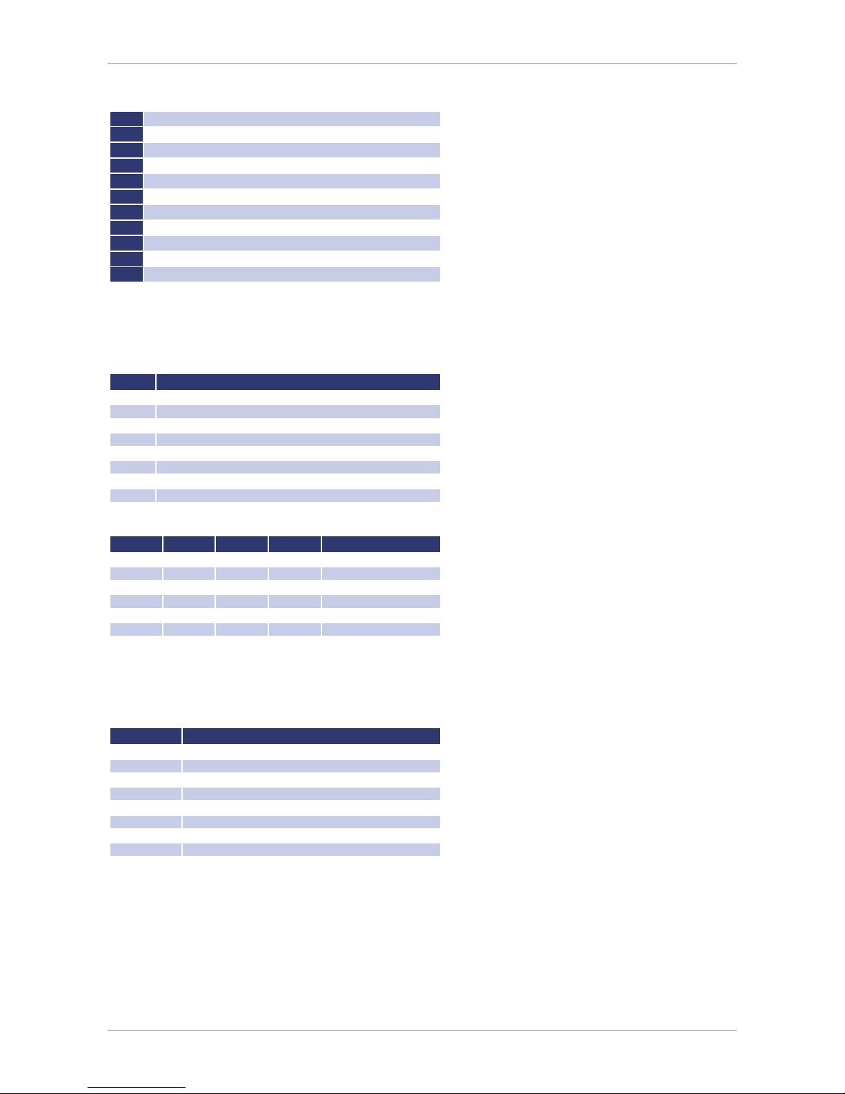
Status Word
The status word can be read with the command
<STB>
or
<*STB?>
. Return value: STB,xxxxxxxx
Table: Reading the status word
Bit Function
D7 n/a
D6 SRQ is set, if SRQ was requested
D5 ESB is set, if a byte was set within the SES
register
D4 MAV is set, if a message is available
D3 n/a
D2 see table
D1 see table
D0 see table
Table: Error messages
D3 D2 D1 D0 Error
0 0 0 1 Syntax
0 0 1 0 Command
0 0 1 1 Range
0 1 0 0 Unit
0 1 0 1 Hardware
0 1 1 0 Read
ESR-Register - Event-Status-Register
The ESR register can be read using the command
<*ESR?>
. Return value: ESR,xxxxxxxx. After the query, the ESR
register is deleted.
Bit Function
D7 Power on
D6 Command error
D5 User request
D4 Execution error
D3 Device dependent
error
D2 Query error
D1 Request control
D0 Operation complete
RS232
INTERFACE
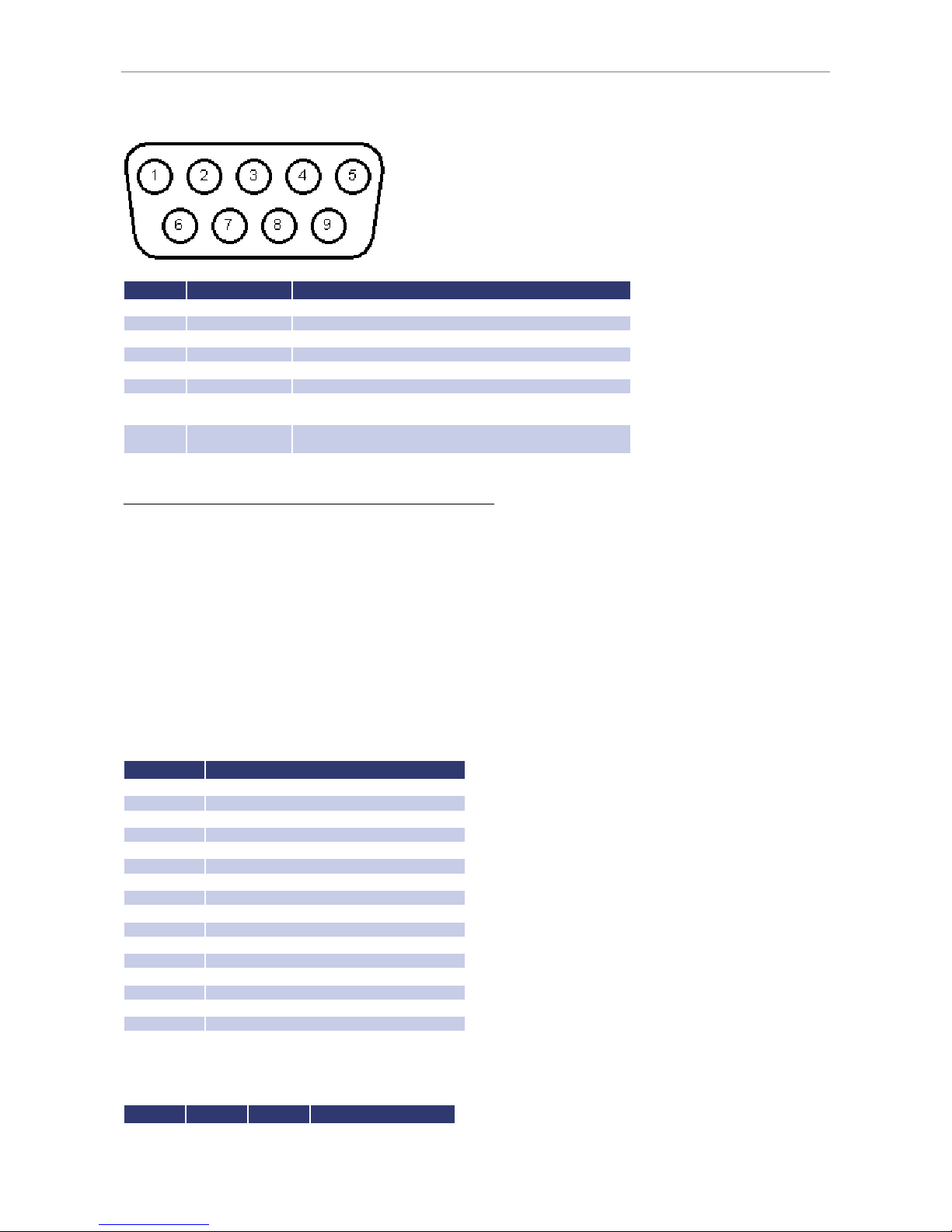
The connection of the RS232 interface is carried out with a 9pin sub D connector.
Page 31
Ext. Control: Computer
No Name Function
1 N.C.
2 TxD Data line from unit to PC
3 RxD Data line from
PC to unit
4 N.C.
5 GND GND
6 N.C.
7 CTS
Reception of the PC, signal direction from PC to unit
(only required for active Hardware handshake)
8 RTS
Reception of the unit, signal direction from unit to PC
(only required for active Hardware handshake)
9 N.C.
The interface can be operated using the following parameters:
Baud rate: 1200, 2400, 4800, 9600, 14400, 19200, 38400, 57600, 62500, 115200
Parity: O = Odd = uneven parity
E = Even = even parity
N = None = no parity bit
Number of data bits: 7 or 8
Number of stop bits: 1 or 2
Handshake: H = Hardware
S = Software
N = None (no handshake)
The defined character for XON is 0 x 11 and for XOFF it is 0 x 13.
Interface parameters in delivery state are 9600 baud, no parity, 8 data bits, 1 stop bit, echo on. The status word can be
read with the command
<STB>
or
<*STB?>
. The following functions are assigned to the bits:
Bit Function
D15 Parity error
D14 Over
run error
D13 Framing error
D12 Timeout error
D11 Echo on
D10 used internally, can be 1 or 0
D9 Hardware handshake (RTS/CTS)
D8 Software handshake (XON/XOFF)
D7 Parity enable
D6 Parity mode (1 = odd, 0 = even)
D5 Stop bit (1 = 2 stop bits; 0 = 1
stop bit)
D4 Data format (1 = 8 bit; 0 = 7 bit)
D3 used internally, can be 1 or 0
D2
Table
D1
Table
D0
Table
Table: Error messages
D2 D1 D0 Error
0 0 1 Syntax
Page 32

Ext. Control: Computer
28
0 1 0 Command
0 1 1 Range
1 0 0 Unit
1 0 1 Hardware
1 1 0 Read
If echo is on, the interface confirms each incoming character by sending the same character back to the sender. The
interface parameters can be adjusted via software and the command
<PCx>
. These settings can be saved with the
command
<SS>
.
Interface Reconfiguration
In case, the user has forgotten the active setup, there are two ways of reconfiguring the interface:
• sending the command
<PCx>
from one of the other interfaces
• using the display to configure the interface Interface Parameters
RS485 I
NTERFACE
The interface works with the following parameters:
Baud rate: 1200, 2400, 4800, 9600, 14400, 19200, 38400, 57600, 62500, 115200
Parity: O = Odd = uneven parity
E = Even = even parity
N = None = no parity bit
Number of data bits: 7 or 8
Number of stop bits: 1 or 2
Timeout: 0-100 ms
A timeout is the time between receipt and sending of a message. The connected device is selected by entering the
command and placing the number of the device and ‘#’ before it. When using the word ‚ALL‘ instead of a number, the
following command will be executed by all connected devices (e. g. #1,ID; #22,GTR, #ALL,GTL).
Example:
#1,ID
#22,GTR
#ALL,GTL
The status word can be read with the command
<STB>
or
<*STB?>
. The following functions are assigned to the bits:
Bit Function
D15 Parity error
D14 Over run error
D13 Framing error
D12 Timeout error
D11 n/a
D10 n/a
D9 n/a
D8 n/a
D7 Parity enable
D6 Parity mode (1 = odd, 0 = even)
D5 Stop bit (1 = 2 Stop bits; 0 = 1 Stop bit)
D4 Data format (1 = 8 bit; 0 = 7
bit)
D3 n/a
D2
Table
D1
Table
D0
Table
Table: Error messages
D2 D1 D0 Error
0 0 1 Syntax
Page 33

Ext. Control: AI Interface (Option)
0 1 0 Command
0 1 1 Range
1 0 0 Unit
1 0 1 Hardware
1 1 0 Read
Interface parameters are configured via software using the command
<PCx>
. The settings can be saved with the
command
<SS>
.
Interface Reconfiguration
In case, the user has forgotten the active setup, there are two ways of reconfiguring the interface:
• sending the command
<PCx>
from one of the other interfaces
• using the display to configure the interface Interface Parameters
EXT. CONTROL: AI INTERFACE (OPTION)
The device can be controlled via control signals and by using the analog/digital In/Out.
Page 34
Ext. Control: AI Interface (Option)
30
P
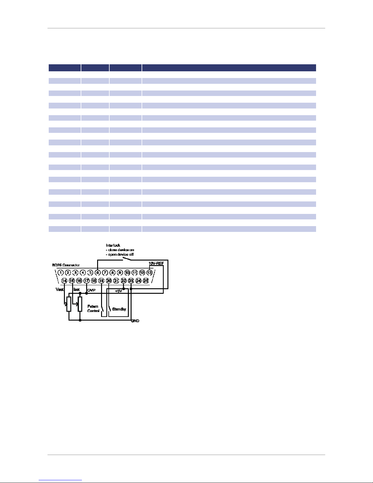
IN ASSIGNMENT AI INTERFACE
No (BD25) Dir Name Function
1 analog out
U
mon
Monitor set point U
2 analog out
I
mon
Monitor set point I
3 analog out
P
mon
Monitor actual value P
4 analog out
OVP
mon
Monitor actual value OVP
5 digital in
Soft-Interlock
Interlock function (Caution: Interlock does not
correspond to the machinery directives)
6 -nc- - -
7 digital out
CV
Signals „Const. Voltage“ mode
8 analog out
U
istmon
Monitor output voltage
9 gnd GND -
10 digital out
Standby
Signals standby
11 gnd GND -
12 -nc- - -
13 REF10 10 V-V
ref
Output 10
V reference voltage
14 analog in
U
set
Set point U
15 analog in
I
set
Set point I
16 analog in
In 2 -
17 analog in
OVP
set
Set point OVP
18 analog in
In 4 -
19 digital in
Ext. Control
Activates analog control
20 digital in
Standby
Activates standby
21 analog out
I
istmon
Monitor output current
22 pwr + 5 V Output 5 V supply voltage
23 gnd GND -
24 digital out
Error Signals shut down by OVP
25 gnd GND -
26 -nc- - -
All digital outputs are OC outputs with a pull-up resistance after + 5 V. All analog inputs and outputs can be operated
in 0-5 V or in 0-10 V mode.
A
NALOG INPUT
Set points are adjusted as dc voltage (0-5 V or 0-10 V) on the analog inputs. The voltage range can be chosen in the
configuration menu.
Set Point U (U
Set
)
Set point output voltage. The set point refers to the rated voltage of the unit.
Page 35

Ext. Control: AI Interface (Option)
Example:
EPS/MP at 600 V output voltage, AI is adjusted to 10 V, desired output voltage = 100 V.
U
set
= 10 V * 100 V ÷ 600 V = 1,667 V
Set Point I (I
Set
)
Set point output current. The set point refers to the rated voltage of the unit.
Example:
EPS/MP at 100 A output voltage, AI is adjusted to 10 V, desired output current = 2 A.
I
set
= 10 V * 2 A ÷ 100 A = 0.200 V
Set Point OVP (U
OVP
)
The output is deactivated immediately if the output voltage exceeds the adjusted value. This error is indicated on the
display with the word „Error“. To rest this error, standby mode must be activated. Adjustment range is 0 V up to the
maximum rated voltage of the device + 20%.
Example:
EPS/MP with 600 V output voltage, AI is adjusted to 10 V, desired OVP voltage = 650 V.
Adjustment range: 600 V + 20% = 720 V
U
set
= 10 V * 650 V ÷ 720 V = 9.028 V
A
NALOG OUTPUT
On the analog outputs, present measurement values are displayed as dc voltage values (regardless of the actual
operation mode). Therefore the AI interface can be used for monitor purposes. Maximum voltage is 5 V / 10 V.
Monitor Set Point U (U
mon
)
Present set point of the output voltage. Measurement value refers to the rated voltage of the device.
Example:
EPS/MP at 600 V output voltage, AI is adjusted to 10 V, voltage at output U
mon
= 2 V.
Present set point: U
set
= 2 V * 600 V ÷ 10 V = 120 V
Monitor Set Point I (I
mon
)
Present set point of the output current. Measurement value refers to the rated current of the device.
Example:
EPS/MP at 100 A output current, AI adjusted to 10 V, voltage at output I
mon
= 2 V.
Present set point: I
set
= 2 V * 100 V ÷ 10 V = 20 A
Monitor Actual Value P (P
mon
)
Present set point for output power. It is calculated by the controller from measurement values of output voltage and
output current. Measure value refers to the rated power of the device.
Example:
EPS/MP at 15 kW rated power, AI adjusted to 10 V, voltage at output P
mon
= 5 V.
Present output power P
out
= 5 V * 15 kW ÷ 10 V = 7.5 kW
Page 36

Ext. Control: AI Interface (Option)
32
Analog Output OVP (U
OVPmon
)
Present set point for over voltage protection. Measurement value refers to the rated voltage of the device + 20%.
Example:
EPS/MP at 600 V output voltage, AI adjusted to 10 V, voltage at output U
mon
= 2 V. Signal refers to 600 V + 20% = 720 V.
Present set point: U
ovp
= 2 V * 720 V ÷ 10 V = 144 V
Monitor Output Voltage (U
Istmon
)
Present measure value point value for output voltage. Measurement value refers to the rated voltage of the device.
Example:
EPS/MP at 600 V output voltage, AI adjusted to 10 V, voltage at output U
istmon
= 6 V.
Present output voltage U
out
= 6 V * 600 V ÷ 10 V = 360 V
Monitor Output Current (I
Istmon
)
Present measure value for output current. Measurement value refers to the rated current of the device.
Example:
EPS/MP at 100 A output current, AI adjusted to 10 V, voltage at output I
istmon
= 4 V.
Present output current I
out
= 4 V * 100 A ÷ 10 V = 40 A
D
IGITAL INPUT
The digital inputs can be used to adjust the operation mode for the analog control. Inputs are low active.
Activation (Ext. Control)
The input ‚Ext. Control‘ can be used to chose the operation mode ‚AI‘. The AI interface is activated by an applied
voltage of + 5 V up to + 10 V. Front panel operation is deactivated. Operation mode is marked as ‚AI‘ on the display.
The digital interface takes priority over the AI interface. The settings from AI interface have no effect if the device is
toggled to ‚Remote‘.
Soft-Interlock
The Interlock deactivates the unit immediately, when the connection between interlock input (Pin 5) and
+5 V voltage is opened. In this case, the output of the unit cannot be activated, neither by interface nor by front panel.
The difference between Soft-Interlock and Interlock is that a Soft-Interlock does not correspond to the machinery
directives. If the Soft-Interlock is triggered, the unit switches into Interlock-Mode.
Blocking (Standby)
The standby mode is activated by an applied voltage of + 5 V up to + 10 V.
The output signal is enabled, if the input ‚Standby‘ is toggled inactive.
D
IGITAL OUTPUT
On the digital outputs, actual device adjustments are displayed (irrespective of the actual operation mode). Therefore
the AI interface may be used for monitoring functions also. Gauges are consistent with a negative logic: S = Set = log.
0; R = Reset = log. 1
A set output has a voltage level of < 0.6 V. A reset output has a voltage level of > 1.2 V.
Blocking (Standby)
The blocking of the output is set, if the unit is in standby mode.
Page 37

Ext. Control: Ethernet (LAN)
C
ONST. VOLTAGE MODE
(CV)
Constant voltage mode is set, when the unit is in constant voltage mode.
E
RROR
An error is set, if the unit has been shut down by OVP. To reset this error, the standby mode must be activated.
EXT. CONTROL: ETHERNET (LAN)
To communicate with the EPS/MP via network, it is necessary to assign an IP address to the device first. In delivery
status, the device automatically draws an IP from the network. In its practical operation, this behavior is unfavorable,
because after each activation the device has a new IP address. Therefore, to each device an individual, permanent IP
address should be assigned.
The status word can be read with the command
<STB>
or
<*STB?>
. Only bits from D0 up to D2 are in use. All other
bits can be 1 or 0.
Table: Error messages
D2 D1 D0 Error
0 0 1 Syntax
0 1 0 Command
0 1 1 Range
1 0 0 Unit
1 0 1 Hardware
1 1 0 Read
M
ANUAL ASSIGNMENT OF AN IP UNDER MICROSOFT WINDOWS
®
After the console has been opened, clicking on ‚Start‘ and ‚Ausführen‘ opens an input field. After this, the command
cmd
or
command
opens a DOS window. The following has to be entered: arp -s xxx.xxx.xxx.xxx yy-yy-yy-yy-yy-yy.
‚xxx‘ is the desired IP address, ‚yy‘ is the MAC address of the unit, which can be read from the unit’s back panel.
The entry of the IP has been added to the ARP table. The device has no new IP yet. Execute telnet with new IP on port
1: telnet xxx.xxx.xxx.xxx 1. ‚xxx‘ is the desired new IP address. Connection fails but the new IP address is thus assigned
to the device. The assignment of the IP is still dynamical, which means that these settings get lost after the device has
been cut off from the network. The user interface can be loaded by entering the new IP address:
http://xxx.xxx.xxx.xxx. By selecting the menu item ‚Config‘, the IP address can be adjusted. Java must be supported by
your browser to adjust the IP.
Page 38
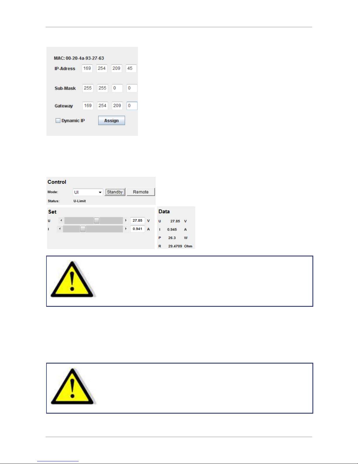
Ext. Control: Ethernet (LAN)
34
M
ONITORING THE DEVICE VIA BROWSER
The user interface opens via direct request of the IP address: http://xxx.xxx.xxx.xxx. The item menu ‚Control‘ opens
the control of the unit. Java must be supported by your browser to control the device.
Whe n co ntr oll ing th e dev ic e via bro ws e r, a not her con tr o l v i a
tel net mu st not be ac tiv e!
C
ONTROLLING THE DEVICE VIA TELNET
The device can be controlled directly via port 10001. After the console has been opened, a click on ‚Start‘ and
‚Ausführen‘ opens an input field. After the commands
cmd
or
command
have been entered, a DOS window opens
with: telnet xxx.xxx.xxx.xxx 10001.
Alternatively, many terminal programs offer the possibility to establish a TCP/IP or telnet connection.
Whe n co n tr oll ing th e de vic e vi a por t 10 001 , th e use r in t er fac e
of the de vic e m ust n o t b e o pen in a br o ws er!
Page 39
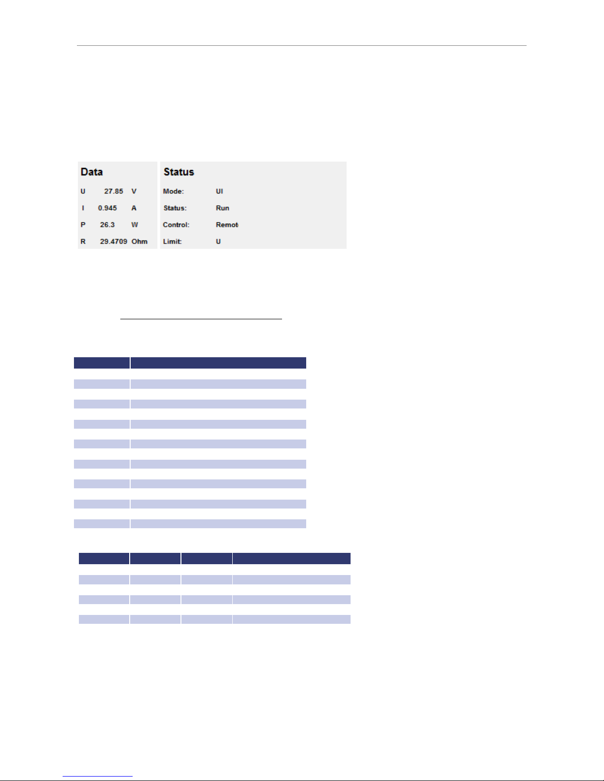
Ext. Control: USB
C
ONTROLLING THE DEVICE VIA BROWSER
The user interface can be opened via IP address: http://xxx.xxx.xxx.xxx. The menu ‚Display‘ opens the monitoring of
the unit. Java must be supported by your browser to control the device. Displayed are all present measurement
values, which are updated every 2 seconds. When using the monitoring function, automatic toggle to remote
operation when receiving a command should be deactivated (command
<GTR,0>
).
EXT. CONTROL: USB
The USB interface provides a virtual COM port for the PC. Via this port, the unit can be controlled as with a normal
RS232 interface, e. g. with a terminal program. Corresponding drivers for all current operating systems are available as
download: http://www.ftdichip.com/Drivers/VCP.htm.
The status word can be read with the command
<STB>
or
<*STB?>
.
Bit Function
D15 Parity error
D14 Over run error
D13 Framing error
D12 Timeout error
D11 Echo on
D10 used internally, can be 1 or 0
D9 Hardware
handshake (RTS/CTS)
D8 Software handshake (XON/XOFF)
D7 Parity enable
D6 Parity mode (1 = odd, 0 = even)
D5 Stop bit (1 = 2 Stop bits; 0 = 1 Stop bit)
D4 Data format (1 = 8 bit; 0 = 7 bit)
D3 used internally, can be 1 or 0
D2
Table
D1
Table
D0
Table
Table: Error messages
D2 D1 D0 Error
0 0 1 Syntax
0 1 0 Command
0 1 1 Range
1 0 0 Unit
1 0 1 Hardware
1 1 0 Read
The defined character for XON is 0 x 11 and for XOFF it is 0 x 13.
Interface parameters are adjusted by software with the command
<PCx>
and afterwards they can be saved with the
command
<SS>
.
I
NTERFACE RECONFIGURATION
In case, the user has forgotten the active setup, there are two ways of reconfiguring the interface:
Page 40
Data Log Function (Option)
36
• sending the command
<PCx>
from one of the other interfaces
• using the display to configure the interface Interface Parameters
DATA LOG FUNCTION (OPTION)
The device has a data log function. A memory card may be used as data logger. All measurement values will be saved,
separated by tabulators, in a text file. The time interval may be adjusted from 1-4294967 s (= 71 minutes). To activate
the data log function, a memory card must be inserted. The root directory of the memory card must contain a text file
named “EPSLOG.txt“. The new data will be written into this file.
The me mor y c ard mu st be i ns ert ed or rem o ve d i n st an dby
mod e o nly !
In case, that the first entry of the first line of the file is "interval=xxxx" (xxxx = time in seconds), the memory interval is
adjusted accordingly. The entry must be written in lower case letters and without space characters. If the interval
remains unspecified, the memory interval is 60 seconds.
Example:
interval=30
The data log function is active whenever the device is not operating in standby mode. The function is indicated by a
small memory card symbol in the upper right corner of the main display. Whenever a new data set is written, the
symbol will be displayed as filled for ca. 1 second. In case the memory card is full, the symbol will be crossed out.
F
ORMAT OF THE SAVED DATA
The first entry shows the present operation mode. The second entry shows the present operation mode followed by
‚Udc‘ and ‚Idc‘.
Example:
USER I-Limit 1,0 10,02
USER OVP 0,0 0,00
UI U-Limit 100,01 0,10
UIP U-Limit 100,0 0,10
SCRIPT MODE
Operation sequences may be programmed in a script which can be read in from a memory card. A script is a text file,
which includes a sequence of commands. Alternatively, the script memory can be programmed via digital interface
using the command
SCR
. For more information about the use of this command see Commands. The device is able
to process up to 250 commands.
E
XECUTING/LOADING A SCRIPT
The script must be saved on a MMC or SD card as text file with .txt or .scr ending.
The mode ‚Scr‘ must be selected from the main display. Pushing the rotary pulse encoder will open the file selection
menu. The script file can be selected. An error message appears if, the file could not be read correctly or, if the read in
Page 41

Script Mode
setup is invalid (e. g. IA 40 at a 10 A unit). To return to the file selection menu, the rotary pulse encoder or the button
Display
must be pushed again. The script has been loaded and can be started by pushing the button
Standby
.
The last five commands of the script are displayed in the field ‚Preset’. The actual command is placed on top. The
script ends when button
Standby
is pushed and device is toggled to standby mode.
C
OMMANDS
Syntax
Upper and lower case are nonrelevant. Therefore, the following commands deliver the same results: PMAX 100 Pmax
100 pMaX 100. Delimiters must be placed between two commands or between command and parameter. Valid
delimiters are: blank, tabulator, LineFeed <LF>, Carriage Return <CR> and equal sign (=).
Numerical values must be placed as basic units and may not be followed by characters. Valid delimiters for decimal
places are: point and comma. No characters must be attached: U 12,345 U 10.00 U 12. The command UAC 12.114V is
invalid, because it is followed by a character.
All commands may be written consecutively, but must be separated by blanks: U 10 I 1 UIP LOOP RUN. Due to its
unclear syntax, this style is not recommendable.
Quick view of commands
Command Description Result
; or # comment
Entering commented text.
DELAY<t>, DELAYS<t>
delay Delays execution of the script for duration of time t.
I<I in ampère>
output current
Set point output current.
IMPP<I in ampère>
MPP current
MPP current in ampère for PV simulation.
LOOP, LOOPCNT
Loop Define return address.
PMAX maximum output
UIP mode
Maximum output for UIP mode.
PV PVsim mode
Activate PVsim mode.
RI internal resistance UIR mode
Set point internal resistance in ohm for UIR mode.
RUN open output
Enable output.
STANDBY
close output
Disable output.
U set point output voltage
Set point output voltage in V.
UI UI mode
Activate UI mode.
UIP UIP mode
Activate UIP mode.
UIR UIR mode
Activate UIR mode.
UMPP set point MPP voltage
Set point MPP voltage (for PV simulation)
USER set points current and voltage
Generates set points
for current and voltage using the internal table.
WAIT wait Waits for user action.
WAVE, WAVELIN
characteristic programming
Characteristic programming.
Detailed description of commands
; or # - Comment
Comment on text. All characters from ; or # up to end of line will be ignored. This function is not available when
programming via digital interface.
Example:
# This is a comment
UIP # This command activates the UIP mode
; Comments can also start with a semicolon
DELAY, DELAYS - Time delay
The commands
DELAY
and
DELAYS
delay the execution of the script. The following number defines the duration of
the delay in ms (milliseconds). Maximum duration of delay is 65535 ms.
Example:
Page 42

Script Mode
38
UI # UI mode
U 10 # Output voltage 10 V
I 1 # Output current 1 A
RUN # Activate output
DELAY 200 # Wait 200 ms
U 100 # Adjust output voltage to 100 V
DELAYS 10 # Wait 10 seconds
STANDBY # Deactivate output
I - Set point output current
This command adjusts the set point for the output current in ampere.
Example:
I 9.8 # Output current 9.8 A
IMPP - Set point MPP current
This command adjusts the set point for the MPP current for PV simulation in ampere.
Example:
IMPP 8.123 # MPP current 8.123 A
LOOP, LOOPCNT - Return Loop
Usually the script ends with the last command. A return address can be defined with the command
<LOOP>
. From
this point on, the processing will continue after the last command of the script. To interrupt the program, button
Standby
must be pushed. The command
<LOOPCNT>
equals the command
<LOOP>
. But here, the command
defines the number of loops. The maximum number is 65535.
Example:
# This example activates the output for 10s, then deactivates it for 2s
# and starts from the beginning. This will continue until the user interrupts the
# process by pushing the button Standby.
UI # UI mode
U 100 # Output voltage 100 V
I 10 # Output current 10 A
LOOP # Start address
RUN # Activate output
DELAYS 10 # Wait 10s
STANDBY # Deactivate output
DELAYS 10 # Wait 2s
# This example works like the previous one.
# The cycle is executed only 10 times, and then the script ends.
Page 43

Script Mode
UI # UI mode
U 100 # Output voltage 100 V
I 10 # Output current 10 A
LOOPCNT 10 # Start address
RUN # Activate output
DELAYS 10 # Wait 10s
STANDBY # Deactivate output
DELAYS 10 # Wait 2s
PMAX - maximum output in UIP mode
Maximum output for the UIP mode.
PV - Pv
sim
mode
Activates the PV
sim
mode.
Example:
PVSIM #Activate PV simulation
RI - Internal resistance UIR mode
This command adjusts the set point for the internal resistance in UIR mode.
RUN - Activate output
The command
RUN
resets the standby mode and activates the output.
Example:
RUN # Activate output
STANDBY - Deactivate output
The command
STANDBY
deactivates the output and activates standby mode.
Example:
STANDBY # Deactivate output
U - Set point output voltage
Set point for output voltage in V.
Example:
U 100 # Output voltage 100 V
UI - UI-Modus
This command activates the UI mode. Unit works current and voltage regulated.
Example:
UI # UI mode
UIP - UIP mode
This command activates the UIP mode. Unit works current, voltage and power regulated.
UIR - UIR mode
This command activates the UIR mode. Unit works current and voltage regulated. Additionally, an internal resistance
is simulated.
UMPP - Set point UMPP voltage
Set point for MPP voltage for PV simulation in V.
Example:
UMPP 80.42 # MPP voltage 80.42 V
Page 44

Script Mode
40
USER - Set points current and voltage
This command generates the set points for current and voltage by using the internal table. Thereby, different UI
characteristics can be created. The tables can be created beforehand by using the command
WAVE
.
WAIT - Waiting for user action
The program is stopped until the user pushes the button
Standby
.
Example:
; Starter characteristic:
UI ; UI mode
I 10 ; Current limitation 10 A
U 12 ; Output voltage 12 V (->100%)
RUN ; Activate output
LOOP ; Start address after end of the script
WAIT ; Waits until rotary pulse encoder is pushed
U 10,5 ; 1. ramp
U 9 ; Command is processed within 1 ms. Therefore the
U 7,5 ; ramp has 5 interim values.
U 6
U 4,5
DELAY 15 ; 15 ms pause
U 4,8 ; 2. ramp
U 5,1 ; Command is processed within 1 ms. Therefore
U 5,4 ; the ramp has 5 interim values.
U 5,7
U 6
DELAY 2000 ; 2000 ms pause
U 6,6 ; 3. ramp
U 7,2 ; Command is processed within 1 ms. Daher
U 7,8 ; The ramp has 10 interim values.
U 8,4
U 9
U 9,6
U 10,2
U 10,8
U 11,4
U 12
WAVE, WAVELIN - Characteristic programming
The command
WAVE
is used to start the characteristic programming. The command is followed by numerical values,
which indicate the desired voltage and current. Finally, followed by the command with a prefixed '-' characteristic (
-
WAVE
).
WAVE
<U1> <I1>
<U2> <I2>
<U3> <I3>
...
<Un> <In>
-WAVE
The command
WAVELIN
equals the command
WAVE
.
WAVELIN
<U1> <I1>
<U2> <I2>
<U3> <I3>
...
<Un> <In>
-WAVELIN
Page 45
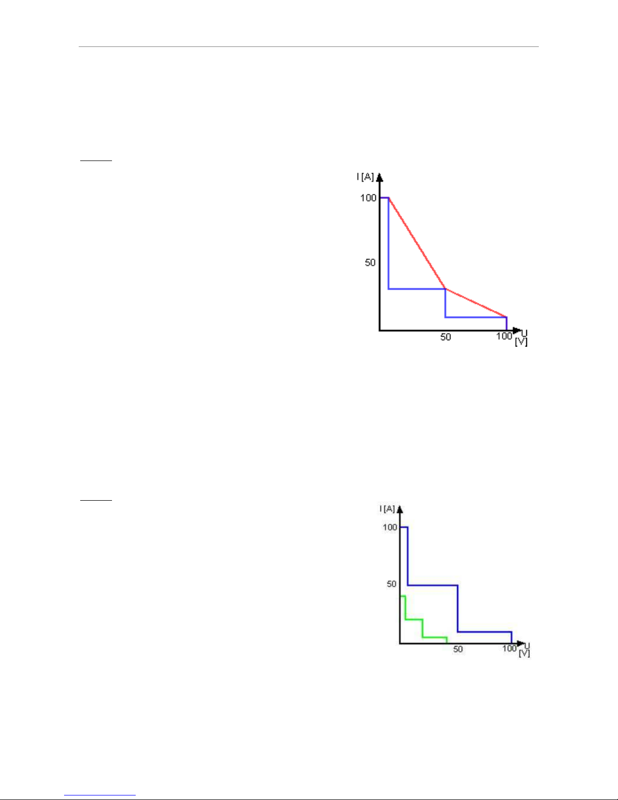
Controller
WAVELIN
With the
WAVELIN
command, the interim values between the fulcrums are linear interpolated, with the
WAVE
command they are layered (see example). Characteristics which are not constant or negative in their course are
accepted but the behavior of the unit may not be predicable.
Example:
; Characteristic with layered interim values
; This script delivers the blue characteristic in the diagram
WAVE ; Start of the table
100 10 ; 100 V 10 A
50 25 ; 50 V 25 A
10 100 ; 10 V 100 A
-WAVE ; End of the table
RUN ; Output active
; Characteristic with linear interim values
; This script delivers the red characteristic
WAVE ; Start of the table
100 10 ; 100 V 10 A
50 25 ; 50 V 25 A
10 100 ; 10 V 100 A
-WAVELIN ; End of the table
RUN ; Output active
If output voltage or output current is changed afterwards, the characteristic keeps its course. Though values are
stretched or compressed to the new range.
Example:
# This script generates a blue characteristic
# After a 10 second delay it switches to the green characteristic:
WAVE # Start of the table
100 10 # 100 V 10 A
50 50 # 50 V 50 A
10 100 # 10 V 100 A
-WAVE # End of the table
U 100 # Output Voltage 100 V
I 100 # Output Current 100 A
USER # Select characteristic
RUN # Output open
DELAY 10000 # Wait 10 seconds
U 50 # Output Voltage 50 V
I 50 # Output Current 50 A
CONTROLLER
The software contains three digital PID controllers. Each controller is assigned to the UIR, UIP and PVsim mode. When
required, the controller parameters can be changed via universal interface.
Page 46
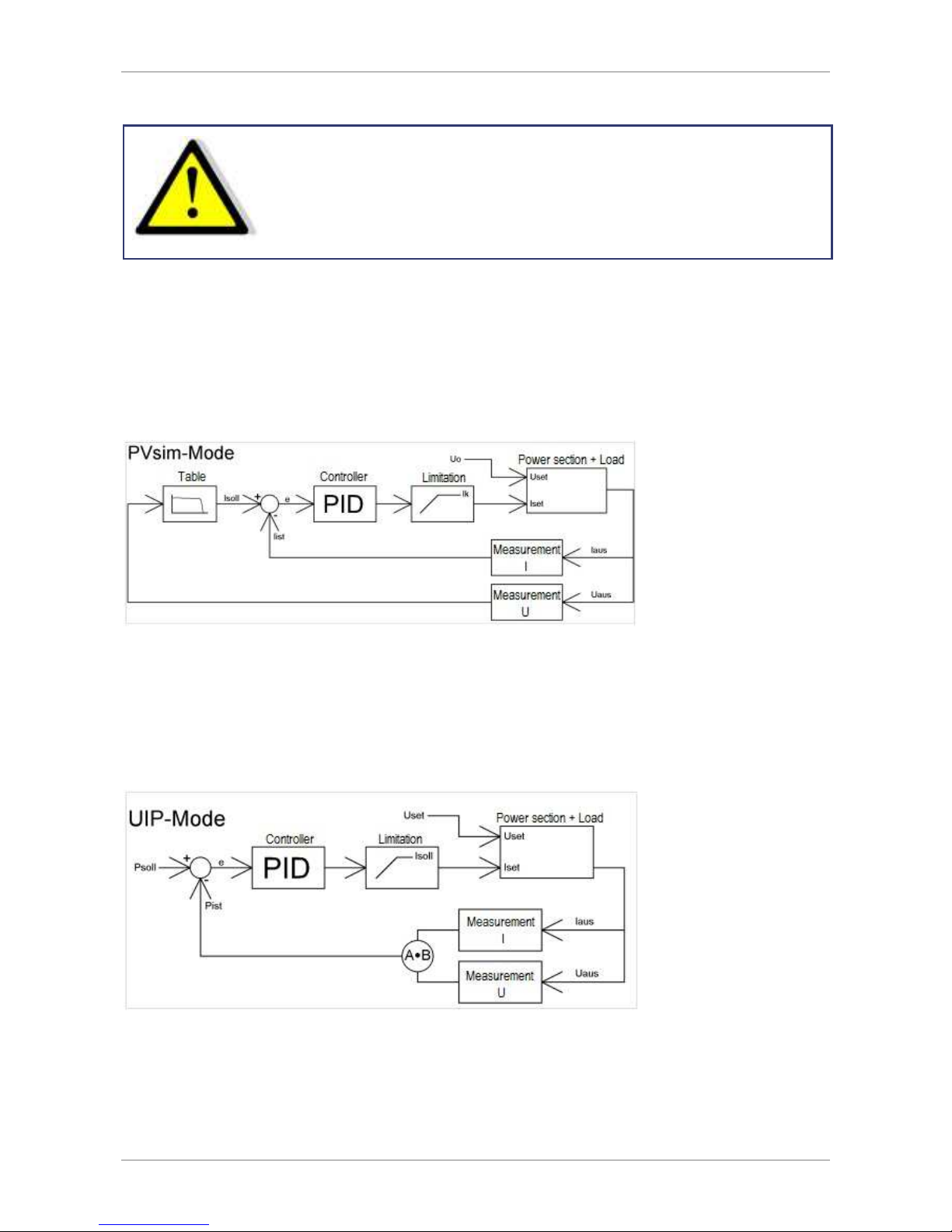
Controller
42
Imp rop er ad j us t men t o f t he co n tr o ll er c an le ad t o c ont rol ler
osc ill ati ons wh ich m a y d ama ge con nec te d d evi c es !
C
ONTROLLER STRUCTURE PVSIM MODE AND USER MODE
The current set point is calculated from the output voltage and a table. This set point stands for the input signal of the
PID controller after it was subtracted from the actual value. The PID controller releases the current set point for the
power supply. The current set point is limited to the short circuit current, as a maximum. The voltage set point of the
power supply is permanently set to the open circuit voltage of the table. In PVsim mode the current is regulated while
the voltage is fixed.
C
ONTROLLER STRUCTURE
UIP M
ODE
The output voltage is multiplied with the output current. The result is subtracted from the power set point. This signal
is the input signal of the PID controller, which releases the current set point for the power supply. The current set
point is limited to the current set point, as a maximum. The voltage set point of the power supply is permanently set
to the voltage set point. In UIP mode the current is regulated, while the voltage is fixed.
C
ONTROLLER STRUCTURE
UIR M
ODE
The measured output current is multiplied with the adjusted internal resistance. The result is subtracted from the
adjusted set point and is then the set point for the voltage controller:
U
soll
= U
set
- Ia * Ri
Page 47
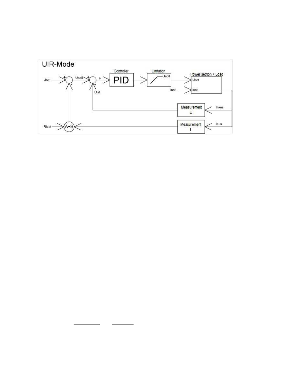
Controller
The output signal is limited to the voltage set point. The current set point of the power supply is permanently set to
I
soll
. In UIR mode the voltage is regulated while the current is fixed.
C
ONTROLLER PARAMETERS
common differential equation of a PID controller:
E Controller deviation
Kp Proportional coefficient
Tn Reset time
Tv Derivative time
Since the digital controller is a discrete-time system, the integral is replaced by a summation and the differential by a
difference:
The following equation puts the controller into practice within the software:
Parameters P, I and D are calculated as follows:
Controller parameters can be programmed via digital interface using the command
REGLER
.
Ts Sampling time
Ts Sampling time = 300 us
( )
⋅
∫
dt
de
Tv+dtte
Tn
+eKp=y
1
y= 0,1Pei+0,001I
∑
m=−
∞
m=i
em+0,1D(ei− e
i−1
)
P= 10Kp I=
1000
Kp
Ts
Tn
D=
10KpTv
Ts
( )
−
−
−∞
∑
1ii
i=m
=m
mi
ee
Ts
Tv
+e
Tn
Ts
+eKp=y
Page 48
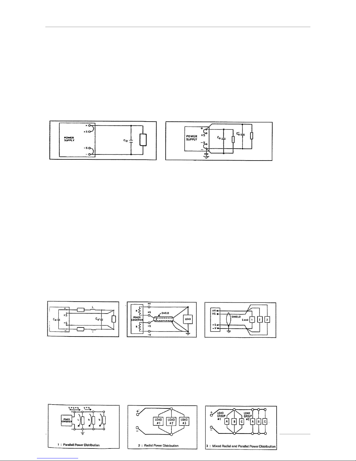
Sense Mode
44
SENSE MODE
L
OAD CONNECTION WITHOUT SENSOR CONDUCTOR
Almost all our power supplies are provided with sensor conductor connectors to compensate the voltage drop on the
load. In case, these connectors are not in use, they must be short-circuited with correct polarity to the load outputs
and directly to the output connectors. By no means, current may flow over the sense connectors. In case of multiple
loads, the user has to provide a central load distribution point. To reduce peak loads and for an HF impedance
terminator, a 1-10 µF capacitor should be connected to the output.
L
OAD CONNECTION WITH SENSOR CONDUCTOR
The following points must be considered, when existing sense cables are connected directly to the load or to the
central load distribution point:
• remove existing sense cable bridges from the power supply
• directly connect + sense and - sense with correct polarity to the load distribution point
• connect + sense and - sense conductors to a 1-47 µF capacitor
• protect sense cable or at least twist + sense and - sense
• select load line cross section, so that voltage drop is < 0.4 V
• avoid overload of power supplies (voltage drop per line x current)
If thus you paid attention to the points stated above, oscillation occurs through load or power induction and complex
load situations, please contact our company EPS.
L
OAD DISTRIBUTION WITHOUT SENSOR CONDUCTOR
To ensure a proper use, a central load distribution situation is essential. Illustration 2 shows a correct load
distribution. Illustration 1 shows an insufficient supply of load 2, load 3 etc. via parallel load conductors. In practice, it
may occur that an optimal distribution is not possible. Illustration 3 shows a mixed distribution, where at least the
largest consumers are supplied centrally.
Page 49
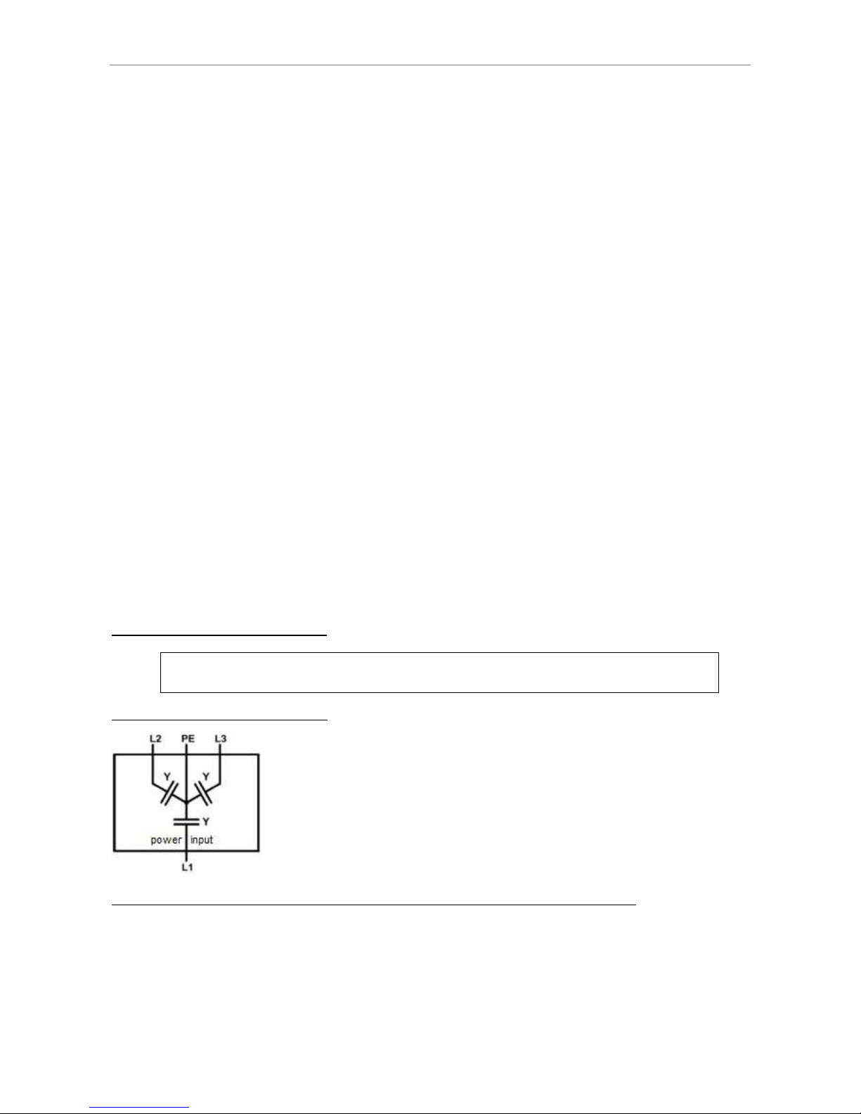
Appendix
APPENDIX
E
QUIVALENT LEAKAGE CURRENT MEASUREMENT ACCORDING TO
VDE 0701
The equivalent leakage current measuring according to DIN VDE 0701-1 may deliver results beyond the norm.
Cause: Measurements are primarily performed on so-called EMC-filters at the AC input of the units. These filters are
built symmetrical, that means capacitors are installed between L1/2/3 and PE. While measuring, L1, L2 and L3 are
connected together and the current flow to PE is measured. Therefore up to 3 capacitors are connected parallel which
doubles or triples the measured leakage current. This is permissible according to the norm.
Quotation from the norm of 2008, appendix D:
„When measuring protection conductor currents with the equivalent leakage current measuring method, it is
important to note that devices with protective grounds and symmetrical circuits may have results, due to the wiring,
that are up to three or four times higher than the leakage current of one phase.“
Graphical representation of a balanced circuit:
Example illustration from the norm protective ground measuring - equivalent leakage current measuring method:
Page 50
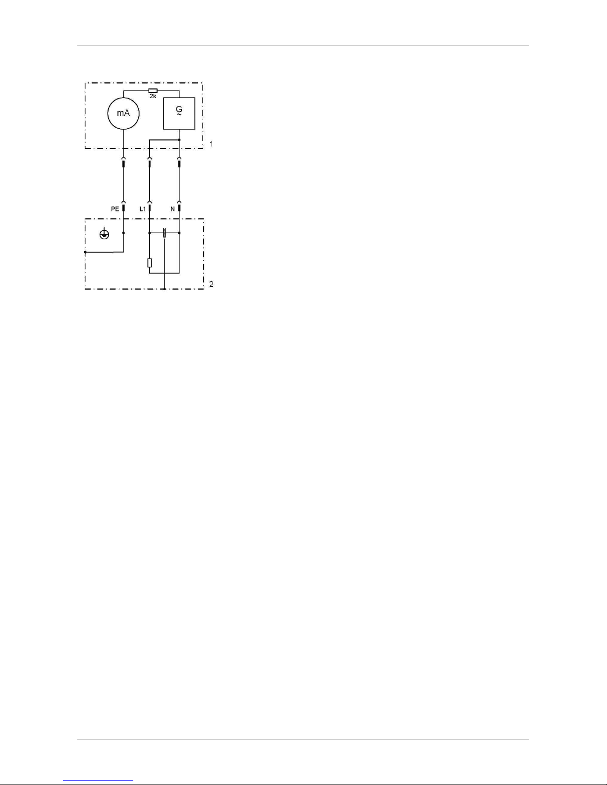
Appendix
46
Note: The illustration shows the measurement method for two-phase power supplies. In the three-phase version, phase N is
replaced by L2 and/or L3.
Page 51

Notes
NOTES
Page 52

Notes
48
Page 53

Notes
 Loading...