


FMK0008970_4083-ESK_30V60A_1~230VAC_PFC_Ah_Ext-Sollwerte_X4_neutral_e.doc 1/41
© Alle Rechte liegen bei m Hersteller. Jegliche Änderung nur mit ausdrücklicher Genehmigung des Autors
Operating manual for
DC power supply
EPS/HC 40030-60
in switch mode technology, air cooled
230V AC / 50-60cps
with PFC (Power Factor Control) for reduced phase current)
with integrated total counter
external control mode (external setpoints) selectable
DC output: 30V / 60A
continuously variable
in constant current and constant voltage regulation
Read this operating manual completely before installation.
Not following installation and operation procedures will void the
warranty. It also could result in serious injury or death.

FMK0008970_4083-ESK_30V60A_1~230VAC_PFC_Ah_Ext-Sollwerte_X4_neutral_e.doc 3/41
List of Contents:
1 General security information ------------------------------------------------------------------- 5
1.1 Class-A device ---------------------------------------------------------------------------------------5
1.2 Security ------------------------------------------------------------------------------------------------5
1.3 Installation of the DC power supply modules ------------------------------------------------7
1.4 Operation conditions -------------------------------------------------------------------------------7
2 General description ---------------------------------------------------------------- -------------- 8
2.1 Switch mode technology --------------------------------------------------------------------------8
2.2 PFC technology--------------------------------------------------------------------------------------8
2.3 Intended purpose------------------------------------------------------------------------------------9
3 DC bus bars --------------------------------------------------------------------------------------- 10
4 Mains supply -------------------------------------------------------------------------------------- 11
5 Operation ------------------------------------------------------------------------------------------ 12
5.1 Main switch ----------------------------------------------------------------------------------------- 12
5.2 LCD display ----------------------------------------------------------------------------------------- 13
6 Key pad functions -------------------------------------------------------------------------------- 14
6.1 The key pads to the right hand side ---------------------------------------------------------- 14
6.1.1 Key „ON“ -------------------------------------------------------------------------------------------- 14
6.1.2 Key „OFF“ ------------------------------------------------------------------------------------------ 14
6.1.3 Key „Enter“ ----------------------------------------------------------------------------------------- 14
6.1.4 Key „CLR“ ------------------------------------------------------------------------------------------- 14
6.1.5 Meaning of flashing LED signals in keypad ------------------------------------------------ 14
6.2 Second key pad row ------------------------------------------------------------------------------ 15
6.2.1 Key „increase voltage“ -------------------------------------------------------------------------- 15
6.2.2 Key „decrease voltage“ ------------------------------------------------------------------------- 15
6.2.3 Key „increase current“ --------------------------------------------------------------------------- 15
6.2.4 Key „decrease current“ -------------------------------------------------------------------------- 15
6.2.5 Special function of the UP / DOWN buttons ------------------------------------------------ 16
6.3 The key pads to the left hand side, F1 – F4, quick menu ------------------------------- 16
6.3.1 Key „F1“Total counter --------------------------------------------------------------------------- 16
6.3.2 Key „F2“Manual / Auto (internal / external setp.) ------------------------------------------ 16
7 Standard functions: current and voltage regulation ------------------------------------- 17
7.1 Up – Down keys ----------------------------------------------------------------------------------- 17
7.2 Constant current regulation --------------------------------------------------------------------- 17
7.3 Constant voltage regulation -------------------------------------------------------------------- 17
8 The total counter --------------------------------------------------------------------------------- 18
8.1 General description ------------------------------------------------------------------------------- 18
9 External setpoints -------------------------------------------------------------------------------- 19
10 Quick menu --------------------------------------------------------------------------------------- 20
11 Setting in main menu --------------------------------------------------------------------------- 21
11.1 General description ------------------------------------------------------------------------------- 21
11.2 Settings ---------------------------------------------------------------------------------------------- 22
11.3 „Additional Settings“ ------------------------------------------------------------------------------ 22
11.4 Info ---------------------------------------------------------------------------------------------------- 22
11.5 Service ----------------------------------------------------------------------------------------------- 23
11.5.1 Reset to default settings ------------------------------------------------------------------------- 23
11.5.2 “Optional features” -------------------------------------------------------------------------------- 23
11.5.3 Releasing optional features --------------------------------------------------------------------- 23
11.6 Setup ------------------------------------------------------------------------------------------------- 24
12 Set values, select settings --------------------------------------------------------------------- 25
12.1 Principle of settings ------------------------------------------------------------------------------- 25
13 Configuration of the total counter ------------------------------------------------------------ 26
13.1 Possible settings of the total counter --------------------------------------------------------- 28
14 Configuration of the peRB --------------------------------------------------------------------- 29
15 Configuration of the external setpoints ----------------------------------------------------- 29

FMK0008970_4083-ESK_30V60A_1~230VAC_PFC_Ah_Ext-Sollwerte_X4_neutral_e.doc 4/41
16 Password ------------------------------------------------------------------------------------------ 31
16.1 Setting------------------------------------------------------------------------------------------------ 31
17 Signals on terminal X4 ------------------------------------------------------------------------- 33
17.1 X4 connecting scheme--------------------------------------------------------------------------- 33
17.2 Extern ON ------------------------------------------------------------------------------------------- 33
17.3 Blocking (switching the DC output OFF) ---------------------------------------------------- 33
17.4 Constant current regulation (CC)-------------------------------------------------------------- 34
17.5 Constant voltage regulation (CV) ------------------------------------------------------------- 34
17.6 Readout values for current and voltage ----------------------------------------------------- 35
17.7 I-act.-Signal 0 … 60mV -------------------------------------------------------------------------- 35
17.8 Error relay ------------------------------------------------------------------------------------------- 35
18 Back plane----------------------------------------------------------------------------------------- 36
18.1 Wiring scheme X4--------------------------------------------------------------------------------- 36
19 Preventative maintenance --------------------------------------------------------------------- 37
20 Technical data ------------------------------------------------------------------------------------ 38
21 Error and function messages ----------------------------------------------------------------- 39
22 Spare parts list ----------------------------------------------------------------------------------- 41
23 Warranty and delivery conditions ------------------------------------------------------------ 41

FMK0008970_4083-ESK_30V60A_1~230VAC_PFC_Ah_Ext-Sollwerte_X4_neutral_e.doc 5/41
1 General security information
1.1 Class-A device
This device is defined as a class-A-device.
Warning: This device is provided to be used only in industrial
environment! In other environments, a sufficient
electromagnetic tolerance could not be assured without additional
installation measures.
1.2 Security
This DC power supply was delivered after a thorough function- and
safety-check. Only qualified staff shall connect the rectifier module and
put it into operation. Service and maintenance is only to be performed by
qualified personnel.
Any manipulation or repairing is life endangering. Observe all instructions
of the manufacturer; else, the warranty for DC power supplies and
accessories will expire.
Parts carrying a life-endangering voltage potential are installed inside the
casing. These are marked with a warning sticker.
Any manipulation of the electrical parts is life endangering and by doing
so, including improper operation, cancels the guarantee.
Attention!
Do not operate any DC power supply with one or more loose cable
connectors!
If during operation one or more plugs are pulled out of the boards
inside the modules, electronic parts and the power unit could be
destroyed!
This DC power supply was constructed in consideration of the threat
analysis and the relevant safety regulations. Further, all relevant
technical specifications are respected. Therefore, this technology is
state-of-the-art and guarantees a maximum of safety and functionality.
The safety and functionality can only be kept if the all relevant
arrangements are done.
The operator of the installation is responsible for the adherence of safety
rules.

FMK0008970_4083-ESK_30V60A_1~230VAC_PFC_Ah_Ext-Sollwerte_X4_neutral_e.doc 6/41
Attention!
Don’t use the handles on the front and back side of the device to
carry or move the device!
Danger of accident!
Consider the high weight and the sharp metal edges of
the device!
Wear individual protective clothing!
The operator has to ensure that
- the DC power supply is only to be used for the application released by
the manufacturer
Active loads such as batteries or generators must never be
connected to the DC generator (danger of destruction)!
- the installation is only to be put into operation if it is in an accurate
condition and all safety devices are checked regularly.
- all requested individual protective equipment for operator and
maintenance personnel is available and is be used.
- the operating and maintenance manual is available and in an accurate
condition
- mounting, repairing, electrical installation, adjusting and maintenance
are only to be performed by qualified personnel.
Security information
The DC-power-supplies of the series EPS/HC 40030-60 can be
operated as desktop or rack-mounting units. If they are not installed
inside cabinets or other casings, make sure that they are protected
against dropping particles, water, dust and vapor!
The manufacturer recommends installing the DC-power-supplies in
cabinets or other protective casings.
The DC power supplies are only to be operated in the permissible ranges
of current, voltage, environmental temperature and atmospheric humidity
according to the rating plate and the operating manual.

FMK0008970_4083-ESK_30V60A_1~230VAC_PFC_Ah_Ext-Sollwerte_X4_neutral_e.doc 7/41
1.3 Installation of the DC power supply modules
While mounting the module and the DC connectors, observe especially
the following:
- Don‘t tighten screws with a lever, don’t bent any rails or panels.
- The units must be mounted in a horizontal way.
- If mounting the units near the plating tanks is necessary, one has to
make sure that they are protected against chemical vapor and dust
and dropping particles.
- Ensure an unhindered airflow at the air input and air output.
- Observe the installation instructions of the electrical installation.
1.4 Operation conditions
DC power supplies are not to be operated in an explosive environment.
Ensure a sufficient airflow to avoid an internal overheating. Always install
the rectifiers directly on to a strong surface and never near an object that
may block the airflow.
Keep a distance from
at least 50cm
from air inlet and outlet to walls or other devices.
The cooling air must be free from any chemical contamination and free
from particles, steam and dust.
The unit must be protected from dropping particles, dripping water and
spalsh water.
The DC power supply should be fixed on the installation place by using
the mounting holes.
Attention!
Never use the front panel to hang up the device as shown on the
sketch below!

FMK0008970_4083-ESK_30V60A_1~230VAC_PFC_Ah_Ext-Sollwerte_X4_neutral_e.doc 8/41
2 General description
The DC-power supply t ype EPS/HC 40030-60 is a sophisticated
switch m ode type rectifier, designed for the industry. It is
designed to fit in a 19”- casing.
The control of the output parameters is done by keys in the front panel of
the unit (internal setpoints mode) or via external analog set signals
(external setpoints mode). The output values are shown on the large,
illuminated display. The display can also show status and warning or
error messages.
The electronic regulation guarantees correct output parameters during
the operation, even with variable loads at the DC output.
Over temperature protection
The device is temperature protected. In case of rising interior
temperature, first the fan speed increases. If the temperature is still
increasing, the device decreases the output current automatically;
in extreme case, the output is set to zero. After a cooling phase, the
output power is increased automatically.
Attention:
Auto-re-start after cooling down!
Do not run the power supply at higher environmental temperatures
than 35°C!
2.1 Switch mode technology
This device was designed as switch mode type DC power supply. The
advantages of the switch mode technology are:
- very compact design
- maximum regulation accuracy
- very low ripple
- high efficiency; power factor cos. 0.95
2.2 PFC technology
The PFC technology (Power Factor Control) allows a reduced phase
current by increasing the efficiency of the power part.

FMK0008970_4083-ESK_30V60A_1~230VAC_PFC_Ah_Ext-Sollwerte_X4_neutral_e.doc 9/41
2.3 Intended purpose
Device for industrial application
According to the norms
DIN EN 61000-3-12 (VDE 0838-12):2012-06
EN 61000-3-12:2011
this device is only to be used for industrial applications. Offering and
selling the device to the general public is not provided.
All other use must be clarified with the technical support of the
manufacturer. Otherwise, the installation or other connected devices
could be damaged.

FMK0008970_4083-ESK_30V60A_1~230VAC_PFC_Ah_Ext-Sollwerte_X4_neutral_e.doc 10/41
3 DC bus bars
The DC output bus bars are located in the rear panel of the device.
Connect the DC output of the DC power supply to the load.
Check for right polarity and proper contact.
Look for the
DIN VDE 0298-4 : 2013-06
admitted cable cross section and the correct polarity.
Attention:
The connection of active loads as batteries or DC-machines to the
DC output would cause damages to the unit!
Please check:
Do not wire the power supply cable and the DC-cables into a roll or bind
the supply cable and the DC-wiring together with other wires. Otherwise,
overheating is possible.

FMK0008970_4083-ESK_30V60A_1~230VAC_PFC_Ah_Ext-Sollwerte_X4_neutral_e.doc 11/41
4 Mains supply
Supply voltage: 230V AC +/-10% 50-60Hz
Phase current: see ”Technical data”
Use the delivered mains cable.
Mains cable specification:
The mains cable must be selected corresponding to the following
regulations:
DIN VDE 0298-4 / 2013-06
Use equivalent regulations that are valid for the country the device is
used in.
Provide for an allowable external fuse admitted to
DIN VDE 0636-2 / 2014-09 / DIN EN 60269-2
Check for the correct environmental temperature (max. 35°C).
Please check:
Make sure that the supply cables could be directly connected to your
main supply.
Avoid the use of cable extensions and multiple power sockets.
Do not wire the power supply or the DC-cables into a roll or bind the
supply and the DC-cables together with other wires. Otherwise,
overheating is possible.

FMK0008970_4083-ESK_30V60A_1~230VAC_PFC_Ah_Ext-Sollwerte_X4_neutral_e.doc 12/41
5 Operation
5.1 Main switch
The DC-power-supply must be switched on by using the main switch in
the front panel (key ON / OFF, to the left hand side).
The LED between the two buttons lights up if the unit is switched on.
After connection to the main supply the following information appear on
the display:
- Checking Memory
- Memory o.k.
- Clearing memory
- Memory cleared
- Initializing memory
- Memory initialized
If the booting sequence is done the pe-logo is shown for a short time.
Afterwards the unit starts the normal operating mode.

FMK0008970_4083-ESK_30V60A_1~230VAC_PFC_Ah_Ext-Sollwerte_X4_neutral_e.doc 13/41
5.2 LCD display
In normal operating mode, the digital display shows the actual current
and voltage parameters of the connected DC power supply.
Below the current and voltage values, the parameters of the additional
functions are shown.
Depending on the operating state, the display can show special
parameters and special functions.
The display can also show error messages.
The display is backlight-illuminated.
The contrast, the display language (menu text) and the illumination can
be configured in the “additional Settings” menu.
FMK0008970_4083-ESK_30V60A_1~230VAC_PFC_Ah_Ext-Sollwerte_X4_neutral_e.doc 14/41
6 Key pad functions
6.1 The key pads to the right hand side
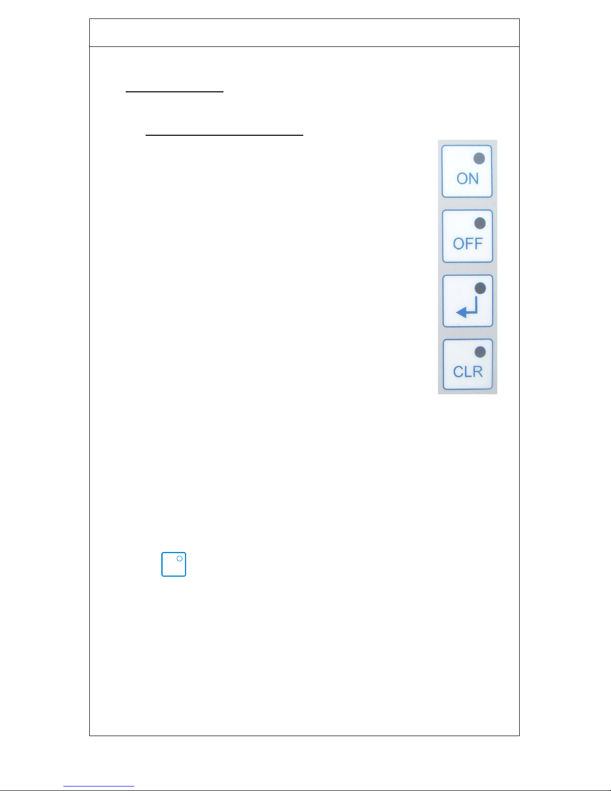
6.1.1 Key „ON“
Switch the connected DC power supply on
ON, if LED lights up
6.1.2 Key „OFF“
Switch the connected DC power supply OFF.
OFF, if LED lights up
6.1.3 Key „Enter“
Open setup menu
Confirm setting
6.1.4 Key „CLR“
Cancel procedure, back to the previous menu
point or to the operating screen (press several
times)
Relay reset
Receipt error and warning messages (press key at least 3sec)
Cancel error and warning messages
6.1.5 Meaning of flashing LED signals in keypad
As a matter of principle:
The LED in the CLR key is flashing if an output relay or the audible alarm
signal can be reset. This is done by a simple press on the CLR key.
The CLR led is also flashing in case of any internal error.
CLR

FMK0008970_4083-ESK_30V60A_1~230VAC_PFC_Ah_Ext-Sollwerte_X4_neutral_e.doc 15/41
6.2 Second key pad row
Up – Down keys:
In internal-setpoints operating mode, the Up – Down keys are used to
adjust the output voltage and current infinitely.
Current and voltage settings:
6.2.1 Key „increase voltage“
Press key to increase the output voltage
If LED lights up: constant voltage regulation
mode
6.2.2 Key „decrease voltage“
Press key to decrease the output voltage
6.2.3 Key „increase current“
Press key to increase the output current
If LED lights up: constant current regulation
6.2.4 Key „decrease current“
Press key to decrease the output current
As soon as one of the four keys is pressed, the display switches from
operating mode to setting mode for current and voltage setting.
Short pressing on the key changes the value by one digit.
Constant pressing causes continuous change of the value.
The changes can be also be done if the OFF button was pressed
(DC power supply switched off).
After two seconds without key actuation the actual values are
indicated again.
In setting menu, the arrow keys are used to select an item and to adjust
the values.

FMK0008970_4083-ESK_30V60A_1~230VAC_PFC_Ah_Ext-Sollwerte_X4_neutral_e.doc 16/41
6.2.5 Special function of the UP / DOWN buttons
If the current UP / down keys or the voltage UP / DOWN keys are
pressed at once, there is a special behavior of the value setting. The set
values are jumping in three steps:
step 1 step 2 step 3
0A 50% nominal current 100% nominal current
respectively
0V 50% nominal voltage 100% nominal voltage
6.3 The key pads to the left hand side, F1 – F4, quick menu
6.3.1 Key „F1“Total counter
Quick menu for “reset actual count”
6.3.2 Key „F2“Manual / Auto (internal / external setp.)
Mode selection:
Manual (LED off) (internal setpoint)
Auto (LED on) (external setpoints via X4 terminal)
Key „F3“
not used in this version
Key „F4“
not used in this version

FMK0008970_4083-ESK_30V60A_1~230VAC_PFC_Ah_Ext-Sollwerte_X4_neutral_e.doc 17/41
7 Standard functions: current and voltage regulation
Setting of the output voltage and output current in standard
operating mode (Manual mode)
7.1 Up – Down keys
The Up – Down keys are used to adjust the output voltage and current
infinitely.
7.2 Constant current regulation
If a constant current is needed, follow these terms:
First move the output voltage to the highest admitted level for your
process by using the “Voltage Up” or “Voltage Down” key.
Now use the “Current Up key” or “Current Down key” to adjust your DCcurrent.
The selected output voltage and current values are shown on the digital
displays.
The LED in keypad “Current Up” lights up if the
current set value is reached at the DC output.
After two seconds without key actuation the actual values are
indicated again.
7.3 Constant voltage regulation
If a constant voltage is needed, follow these terms:
First move the output current to the highest admitted level for your
process by using the “Current Up” or “Current Down” key.
Now use the “Voltage Up key” or “Voltage Down key” to adjust your DC-
voltage.
The selected output voltage and current values are shown on the digital
displays.
The LED in keypad “Voltage Up” lights up if the
voltage set value is reached at the DC output.
After two seconds without key actuation the actual values are
indicated again.
UVI
A
I
A
I
A
IAU
V
U
V
U
V

FMK0008970_4083-ESK_30V60A_1~230VAC_PFC_Ah_Ext-Sollwerte_X4_neutral_e.doc 18/41
8 The total counter
8.1 General description
The total counter allows the measurement of the actual current with
switchable measuring ranges ampere hours, ampere minutes, ampere
seconds, 1/10 000Ah and gram-silver, gram gold.
The actual counter reading is shown down in the display (line: “Total c.“)
Possible settings for the total counter
The following counting ranges are available:
Ah = Ampere hours
Am = Ampere minutes
As = Ampere seconds
0.0001Ah = 1 ten-thousandth part of ampere hour
gS = Gram silver
gG = Gram Gold (single weighted 3-weighted)
- Set decimal point
Attention
Each digit set after the decimal point reduces the digits before the
decimal point!
Example:
If you set ampere-hours with three digits after the decimal point
only two digits before the decimal point can be shown (99.999Ah).
If you set zero digits after the decimal point five digits before the decimal
point can be shown (99999Ah)
- Delete actual count
- Delete overflow indication
Attention:
The actual values (Ah, Am, As, 0.0001Ah, gS, gG) are deleted by
switching the unit or changing the decimal places!
The actual count is stored if the main switch of the unit is switched
off or if the unit is disconnected from mains.

FMK0008970_4083-ESK_30V60A_1~230VAC_PFC_Ah_Ext-Sollwerte_X4_neutral_e.doc 19/41
9 External setpoints
In “External mode”, the DC power supply is controlled via external
setpoints (terminal X4, see wiring scheme).
If “External setpoints” is activated the current and voltage Up / Down
keys are deactivated.
The switching is done via key F2.
The display shows: Setpoints: extern
In “External setpoints mode”, the control signals for current and voltage
I-set and U-set are 0 … 10V each. These signals are supplied at terminal
X4.
The digital displays will show the actual output values. The readback
values are given out indirect-coupled on the X4-terminal
(signals: 0 … 10V each).

FMK0008970_4083-ESK_30V60A_1~230VAC_PFC_Ah_Ext-Sollwerte_X4_neutral_e.doc 20/41
10 Quick menu
F1 key: Quick menu for the total counter (reset the actual count).
F2 key: External setpoints
By pressing any F key in standard operating mode the following display
is shown:
Press F1 to reset the actual count
Press F1 to toggle between Manual and Auto mode
By using the quick menu function you can set the parameters of the
additional functions directly.

FMK0008970_4083-ESK_30V60A_1~230VAC_PFC_Ah_Ext-Sollwerte_X4_neutral_e.doc 21/41
11 Setting in main menu
11.1 General description
Open the main menu by pressing the ENTER key.
The display shows:
Select the desired menu point by pressing the corresponding key.
(Press CLR-key to come back to the main menu screen.)
If no optional features like Ah counter, Preset counter, Timer, Ramp or
external control are released, the menu item “Settings” is deactivated
(the text color is grey).
CLR

FMK0008970_4083-ESK_30V60A_1~230VAC_PFC_Ah_Ext-Sollwerte_X4_neutral_e.doc 22/41
11.2 Settings
The SETTINGS menu is the menu for the process settings:
- Total counter
- External setpoints
Press the F1-key to come to this menu
Select the remaining sub items of this menu point by pressing the
corresponding keys (F2, F3, F4 and „decrease current“).
11.3 „Additional Settings“
contains the adjustments for:
- Display language
- Key click
- Display illumination
- Display contrast
- Relay assignment
If you want to adjust one of these items, press the F2 key
in the main menu.
Attention:
All additional settings can interfere with the function of the unit, and
should only be carried out after an agreement with the service-section of
manufacturer.
By opening the menu “additional settings” a warning message appears.
If you are sure to carry out changes confirm the message with the
F4 key.
11.4 Info
contains the information (no settings!) about:
- Version No.
- Build counter
- Nominal output voltage
- Nominal output current
- Max. output voltage
- Max. output current
- Serial No.
If you want to see one of these information press the F3 key
(in main menu).
F3
F2

FMK0008970_4083-ESK_30V60A_1~230VAC_PFC_Ah_Ext-Sollwerte_X4_neutral_e.doc 23/41
11.5 Service
In this menu item, you find the manufacturer address, telephone- and
facsimile Number.
If service or maintenance is required, several default settings can be
revised, after entering the access code.
11.5.1 Reset to default settings
To reestablish the default settings of the unit the
Code: 130
is to be entered here (press F1 key in the submenu “Service”, then set
up the value to 130, by using the “Current up/down keys”).
11.5.2 “Optional features”
In the submenu „Settings” all available optional features are listed.
Any function has to be unlocked with a releasing-code delivered by
manufacturer.
11.5.3 Releasing optional features
To release optional features, press the „Voltage increase“ key in the
menu item “Service”.
In this menu, the following optional features can be activated (for every
feature that is not released by the manufacturer, a releasing code is
requested):
- Total counter / preset counter (enabled)
- RS485-BUS controlling (enabled)
- Ramps
- Timer
- DC steps
- Chopper Timer
- Voltage or current monitoring (enabled)
- Pole changer
- Current density regulation
- Operating hour counter
Attention:
Not all functions can be combined with each other!
It is not possible to enable all functions simultaneous.
Some features are only available with special hardware equipment and
cannot simply be released by software code.
Please ask our sales manager for further information!

FMK0008970_4083-ESK_30V60A_1~230VAC_PFC_Ah_Ext-Sollwerte_X4_neutral_e.doc 24/41
11.6 Setup
The settings in this menu point are only available for the manufacturer
service team. General device parameters are set here.
To enter this menu point a releasing code is requested.
End of main menu.
Press the CLR key once or several times to come back to the previous
menu points and back to operating mode.
CLR

FMK0008970_4083-ESK_30V60A_1~230VAC_PFC_Ah_Ext-Sollwerte_X4_neutral_e.doc 25/41
12 Set values, select settings
In the menu points described above you can set values or select
functions.
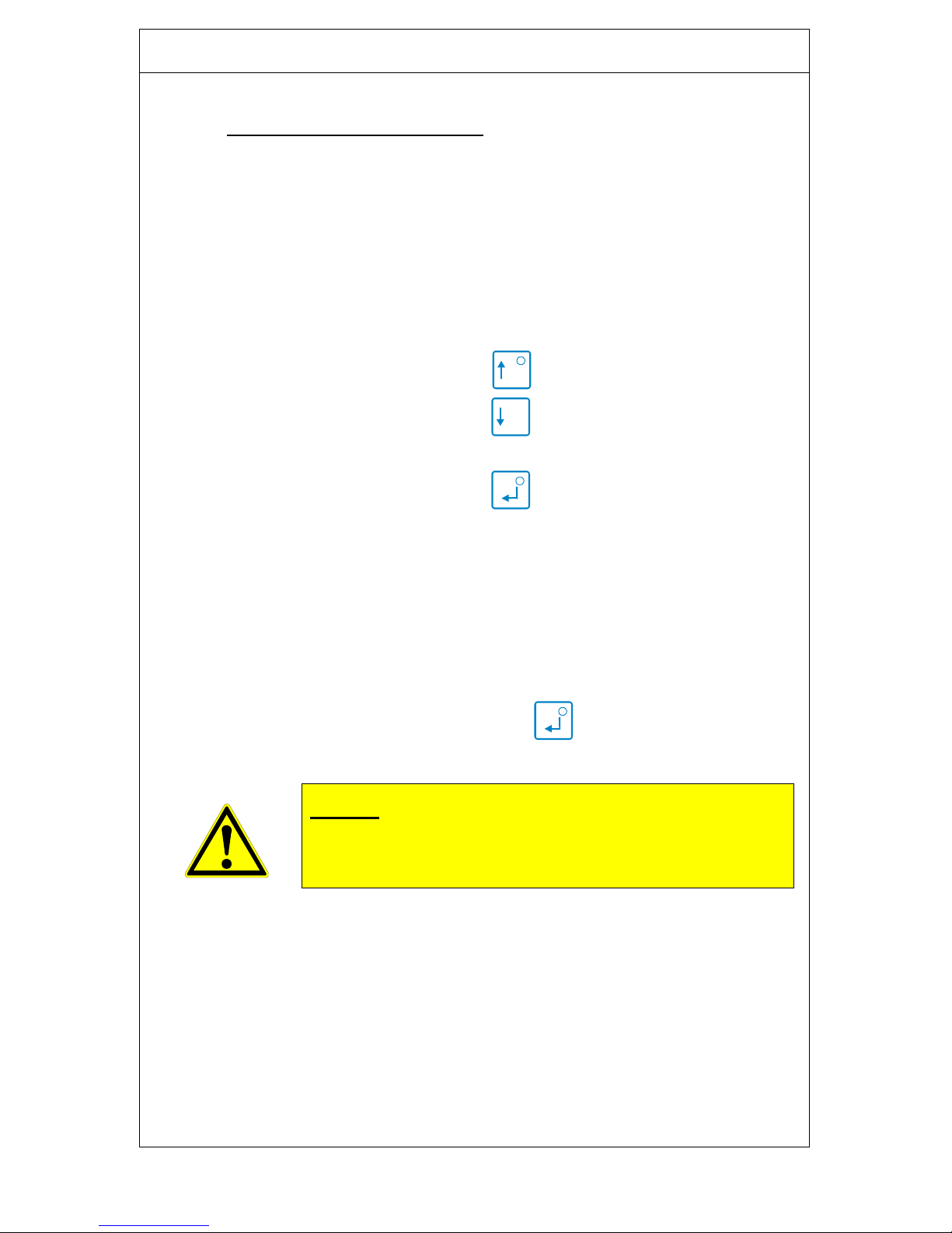
12.1 Principle of settings
Use the keys to select the line whose parameters you want to
change.
Example: Additional settings:
Set the desired value or selection point by the Up / Down keys
Confirm with ENTER.
Press the CLR key once or several times to come back to the previous
menu points and back to operating mode.
This principle is effective for all settings.
I
A
Set value
U
V
U
V
Select line
I
A
CLR

FMK0008970_4083-ESK_30V60A_1~230VAC_PFC_Ah_Ext-Sollwerte_X4_neutral_e.doc 26/41
13 Configuration of the total counter
If you are in normal operating mode (current and voltage display):
Open the main menu by pressing the ENTER key.
The display shows:
Press the F1-key:
The display shows:
Press the F1-key:
FMK0008970_4083-ESK_30V60A_1~230VAC_PFC_Ah_Ext-Sollwerte_X4_neutral_e.doc 27/41
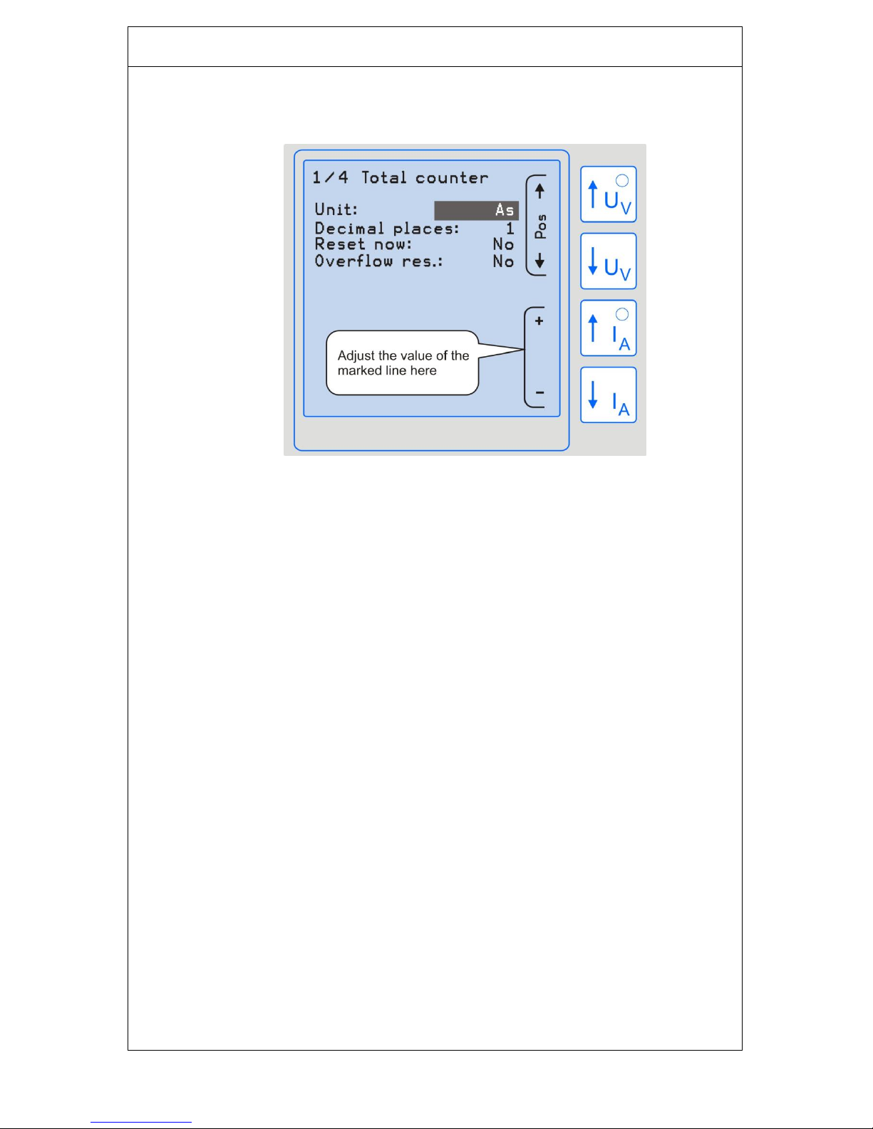
The display shows:
Select the line by voltage UP / DOWN keys.
FMK0008970_4083-ESK_30V60A_1~230VAC_PFC_Ah_Ext-Sollwerte_X4_neutral_e.doc 28/41
13.1 Possible settings of the total counter
The following counting ranges (unit) are available:
Ah (Ampere hours)
Am (Ampere minutes)
As (Ampere seconds)
0.0001Ah (1 ten-thousandth part of ampere hour)
GramSil (Gram silver)
GrGold I (Gram gold, univalent)
GrGo III (Gram gold, trivalent)
The setting is done by the keys.
Confirm with ENTER.
Further items in this menu point:
Decimal places: 0, 1, 2, 3
Reset now (delete actual count) yes / no
Overflow reset yes / no
Confirm each setting with ENTER.
Attention:
The actual values are deleted by changing the unit (Ah, Am, As,
0,0001Ah, gS, gG) or changing the decimal places!
The actual count is stored if the main switch of the unit is switched
off or if the unit is disconnected from mains.
IAI
A

FMK0008970_4083-ESK_30V60A_1~230VAC_PFC_Ah_Ext-Sollwerte_X4_neutral_e.doc 29/41
14 Configuration of the peRB
No setting to be done by customer in this menu point!
15 Configuration of the external setpoints
If you are in normal operating mode (current and voltage display):
Open the main menu by pressing the ENTER key.
The display shows:
Press the F1-key.

FMK0008970_4083-ESK_30V60A_1~230VAC_PFC_Ah_Ext-Sollwerte_X4_neutral_e.doc 30/41
The display shows:
Press the F3-key.
The display shows:
Select via keys between “internal” or “external setpoints”
Quick menu: The switching is done via key F2.
Ext. switch: This setting must be set to “No”!
IAI
A

FMK0008970_4083-ESK_30V60A_1~230VAC_PFC_Ah_Ext-Sollwerte_X4_neutral_e.doc 31/41
16 Password
The password menu is used to protect the settings areas (menu
„Settings“ and menu „Additional settings“)
If the password is set, the protected areas could just be opened if the
password is entered.
There are eight digits to be set.
Disable password: set all digits to zero (0 0 0 0 0 0 0 0)
16.1 Setting
If you are in normal operating mode (current and voltage display):
Open the main menu by pressing the ENTER key.
The display shows:
Press the F1-key:
Press the “Voltage-UP / Voltage-DOWN” keys to change the menu page.
Select the „Password“ menu:
Press the corresponding F-key to open the menu.
FMK0008970_4083-ESK_30V60A_1~230VAC_PFC_Ah_Ext-Sollwerte_X4_neutral_e.doc 32/41
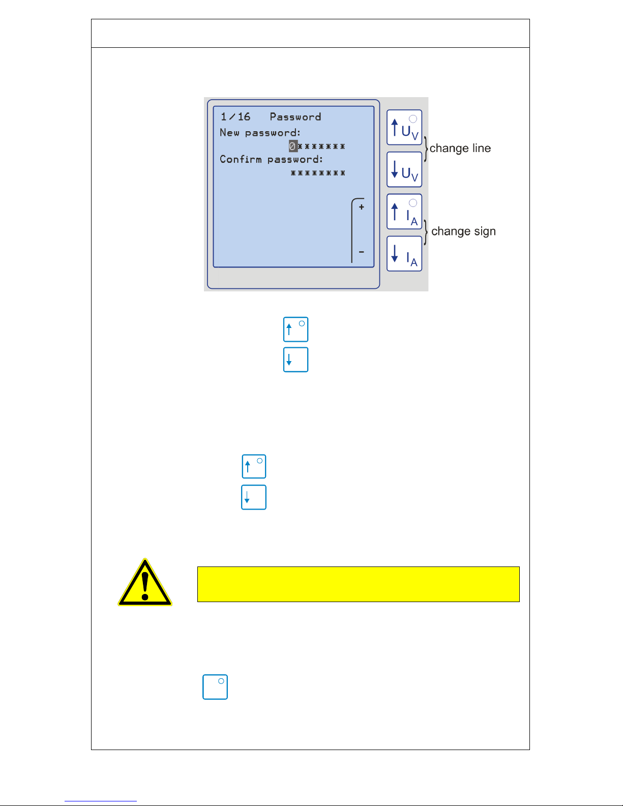
The display shows:
For each digit, select the cipher 0 to 9
by using the keys
Press ENTER to confirm each digit.
Confirm password:
Use the keys to change the line:
Repeat the password setting here in this line.
Confirm each digit with ENTER.
Make sure the password is noted somewhere!
Disable password: set all signs to zero (0 0 0 0 0 0 0 0)
Press the CLR key once or several times to come back to the previous
menu points and back to operating mode.
IAIAU
V
U
V
CLR

FMK0008970_4083-ESK_30V60A_1~230VAC_PFC_Ah_Ext-Sollwerte_X4_neutral_e.doc 33/41
17 Signals on terminal X4
17.1 X4 connecting scheme
17.2 Extern ON
To switch the DC power supply ON, use the Extern-ON function. It is
wired to pin 10 (GND) and pin 12 (ON) of the X4-terminal.
Attention:
The unit is not disconnected from mains if the function is set to
OFF!
Use only potential free contacts!
Consider:
If the BLOCKING contact (see below) is closed, the unit could not be
switched on! The BLOCKING function has priority!
17.3 Blocking (switching the DC output OFF)
To switch the DC output OFF, use the BLOCKING function. It is wired
to pin 10 (GND) and pin 13 (BLOCKING) of the X4-terminal.
Attention:
The unit is not disconnected from mains if the DC output is set to
BLOCKING!
Use potential free contacts!

FMK0008970_4083-ESK_30V60A_1~230VAC_PFC_Ah_Ext-Sollwerte_X4_neutral_e.doc 34/41
17.4 Constant current regulation (CC)
If a constant current is needed, follow these terms:
First move the output voltage to the highest admitted level for your
process using the voltage set signal U-set: Supply 10V DC to X4/6
(related to X4/3, GND). If possible, use the Uref. signal 10.2V DC at X4/5
to set the output voltage to maximum. If another signal than the Uref.
signal is used, the GND potential of the external control signal is to be
connected to X4/3.
Now use the current set signal I-set to adjust your DC-current: Supply
0 … 10V DC to X4/4 (related to X4/3, GND) to set the output current from
0A to I
nom
. If possible, use the Uref. signal 10.2V DC at X4/5 to set the
output current to maximum. If another signal than the Uref. signal is
used, the GND potential of the external control signal is to be connected
to X4/3.
Both, the current and the voltage readout value I-act. and U-act. , will be
given out at X4/1 and X4/2 (0 … 10V each, related to GND).
Attention:
If one set signal, the current or voltage one, is set to zero the DC output
is blocked!
17.5 Constant voltage regulation (CV)
If a constant voltage is needed, follow these terms:
First move the output current to the highest admitted level for your
process using the current set signal I-set: Supply 10V DC to X4/4
(related to X4/3, GND). If possible, use the Uref. signal 10.2V DC at X4/5
to set the output current to maximum. If another signal than the Uref.
signal is used, the GND potential of the external control signal is to be
connected to X4/3.
Now use the voltage set signal U-set to adjust your DC-voltage: Supply
0 … 10V DC to X4/6 (related to X4/3, GND) to set the output voltage
from 0V to U
nom
. If possible, use the Uref. signal 10.2V DC at X4/5 to set
the output voltage to maximum. If another signal than the Uref. signal is
used, the GND potential of the external control signal is to be connected
to X4/3.
Both, the current and the voltage readout value I-act. and U-act. , will be
given out at X4/1 and X4/2 (0 … 10V each, related to GND).
Attention:
If one set signal, the current or voltage one, is set to zero the DC output
is blocked!

FMK0008970_4083-ESK_30V60A_1~230VAC_PFC_Ah_Ext-Sollwerte_X4_neutral_e.doc 35/41
17.6 Readout values for current and voltage
The read out values I-act. and U-act. are wired up to the terminal X4
pin 1 (I-act.) and pin 2 (U-act).
The signals are
0 ... 10V for 0A ... I
nom
and
0 ... 10V for 0V ... U
nom
.
The signals I-act. and U-act. are related to Ref. GND (pin X4/3).
17.7 I-act.-Signal 0 … 60mV
The I-act. signal 0 … 60mV is a reference signal for the actual output
current.
Signal:
0 … 60mV for 0 … I
nom
: X4/7 = 60mV GND, X4/8 = +0 … 60mV
17.8 Error relay
The error relay is an internal relay that indicates if the DC power supply is
in operation, or if the system is off. The relay contacts are connected to
pin 14 – 16 of the service connector X4.
15 = COM 16 = NC 14 = NO
- relay contact X4/14 and X4/15 closed = in operation
- relay contact X4/16 and X4/15 closed = mains supply OFF,
or internal error.
Attention:
The Extern-ON function and the BLOCKING function do not influence the
error relay!
The error relay is switching to “Error / OFF” position (15 / 16 closed) if
there is an internal error, missing phase or low voltage.
Attention!
Do not overload the relay contacts!
Max. load of the error relay contacts: 48V / 500mA

FMK0008970_4083-ESK_30V60A_1~230VAC_PFC_Ah_Ext-Sollwerte_X4_neutral_e.doc 36/41
18 Back plane
1 = Main supply
2 = Terminal X4
3 = DC output
4 = Cooling air inlet
5 = Fuses
18.1 Wiring scheme X4

FMK0008970_4083-ESK_30V60A_1~230VAC_PFC_Ah_Ext-Sollwerte_X4_neutral_e.doc 37/41
19 Preventative maintenance
This device is extensively maintenance-free.
It is recommended to perform the following maintenance tasks at regular
intervals:
- Clean the fan and the air duct
- Check up the fan on functionality and unusual noises
- Verify the quality and cleanliness of the cooling air
- Visual check of the casing (protecting grade still kept?)
- Visual check of all accessible electrical connections within the
casing
- Check up all connections done by the customer
The maintenance intervals are to be defined by the customer and / or
operator. The intervals are depending on the environmental conditions
and operation cycles.
Do not clean the units with strong cleaning agents. Adjustment and
maintenance work should only be done under strict safety precautions,
especially if the work must be done while the device is switched on.
Inside the unit, there are no controls to be used during operation.
This device was manufactured under high quality standards and has
passed several function and safety tests during the production process. If
there should be any trouble however, please contact the manufacturer.
FMK0008970_4083-ESK_30V60A_1~230VAC_PFC_Ah_Ext-Sollwerte_X4_neutral_e.doc 38/41
20 Technical data
Device t ype:
EPS/HC 40030-60
Function:
DC power suppl y
Mains voltage:
1~ 230V AC +/-10% 50-60Hz
Phase current::
9.5A / phase at nominal DC output and
nominal supply voltage
(PFC technology)
Neutral:
no
Advised cable cross section for
mains cable:
according to
DIN VDE 0298-4 / 2013-06
DC-output voltage:
0 ... 30V, infinitely variable
DC-output current:
0 ... 60A, infinitely variable
Display resolution:
10mV / 100mA
Advised cable cross section for DC
cable:
according to
DIN VDE 0298-4 / 2013-06
Ripple:
< 1% of nominal voltage at 300cps *)
Regulation inaccuracy:
voltage: < 0.5%; current: < 1% *)
Cyclic duration factor:
100 %
Environmental temperature:
0 to +35°C
Noise suppression:
according to EN 55011 curve A
Protection grade:
IP20
Cooling:
Air, by fan
Cooling air consumption:
100m3/h
Weight:
app. 25kg
Dimensions:
482 x 134 x 520 (W x H x D)
Casing (color):
stainless steel
*) valid for 2 – 100% of the nominal values
Other features:
- automatic turn off at under- and over voltage with defined start level
- protection against short circuit and open circuit
- over temperature protected
- efficiency > 85 % (switch mode technology)
- power factor cos. 0.95

FMK0008970_4083-ESK_30V60A_1~230VAC_PFC_Ah_Ext-Sollwerte_X4_neutral_e.doc 39/41
21 Error and function messages
Function messages
Description
What to do?
Warning thresh.:
U/I Monitoring
Exceeding of the preset warning threshold
(only if U/I monitoring is activated)
Check the tank contacts and the
internal resistance of the tank.
Preset current respectively voltage
values are achieved?
Alarm thresh.:
U/I Monitoring
Exceeding of the preset alarm threshold
(only if U/I monitoring is activated)
Check the tank contacts and the
internal resistance of the tank.
Preset current respectively voltage
values are achieved?
Error:
Overload detected!
Overload (short circuit) on the output
detected (only at overload detection)
Check short circuit at the tank /
work piece→ check the tank!
Error messages
(in alphabetical order)
Description
What to do?
Error:
Operation relay off!
Indication relay of the power supply not
operated
Check the operating state of the
power supply:
- Main supply at the power supply
is missing
-Excess temperature
Contact service
Error:
Bus logging
Card full!
MMC/SD logging defective
(only for devices with MMC/SD card)
Install card with free memory
capacity
Error:
Bus logging
Buffer full!
MMC/SD logging defective
(only for devices with MMC/SD card)
Replace card
Without success: contact service
Error:
Bus logging
Write error!
MMC/SD logging defective
(only for devices with MMC/SD card)
Check card for correct
formatting and for free memory
capacity
RAM- Error:
„Memory check failed!”
RAM defective
Contact service
EEPROM- Error:
“Setup Error#X“
Saved setup data are defective
Reset to manufacturer setting
(see operating manual)
Without success: contact service
EEPROM- Error:
“ Config#X“
Saved configuration data are defective
Check configuration
Reset to manufacturer setting
(see operating manual)
Contact service
EEPROM- Error:
“ Setpoint Error#X“
Saved set value data are defective
Enter set values again
(continued processing possible)
Contact service
EEPROM- Error:
“ Actual Value Error#X”
Actual values lost
Contact service
(continued processing possible)
Error:
End switch 0x0000
End switch of pole changing defective
(only for devices with mechanical pole
changing)
Check the end switch of the
polechanger unit
Without success: contact service
Error:
Reference missing!
Reference voltage of the power supply is
missing
Check main supply
Check LEDs
Check wiring / connector from
control unit to power supply
Without success: contact service

FMK0008970_4083-ESK_30V60A_1~230VAC_PFC_Ah_Ext-Sollwerte_X4_neutral_e.doc 40/41
Error messages
(in alphabetical order)
Description
What to do?
Error:
Voltage tolerance
Voltage error
(in BUS operation, if voltage regulation is
active)
Check the tank contacts and the
internal resistance of the tank.
Preset current respectively voltage
values are achieved?
Error:
Current tolerance
Current error
(in BUS operation, if current regulation is
active)
Check the tank contacts and the
internal resistance of the tank.
Preset current respectively voltage
values are achieved?
Error:
High temperature!
Temperature too high
For water cooled devices:
Check water throughput, inlet
temperature, outlet temperature
Contact service
For air cooled devices:
Check environmental temperature,
air duct, fan grill, filter.
Does the fan turn?
Is the device polluted?
Contact service
Error:
Bus timeout
Preset time for timeout exceeded
→Switch off
Check control software
Warning:
Load out of range!
Current density regulation identifies
error.
Surface of goods out of range
(only if current density regulation is
active)
Adjust surface value,
re-configuration of
current density regulation
Warning:
Powerfail detected!
Count: 1(4=Stop!)
Powerfail:
The supply voltage did fall for a short
period of time
below the admitted tolerance
Number of registered powerfails:
At each powerfail the process relevant
data of the control unit are saved.
If while 10 minutes more than 3
powerfails are detected the software is
stopped.
Check the stability of the
supply voltage of your control unit.
If more than 3 powerfails are
detected: (“count: 4(4=Stop!”)
the control unit has to be reset.
22 Warranty and delivery conditions
The general trading conditions of the manufacturer are effective.
 Loading...