

Page 1
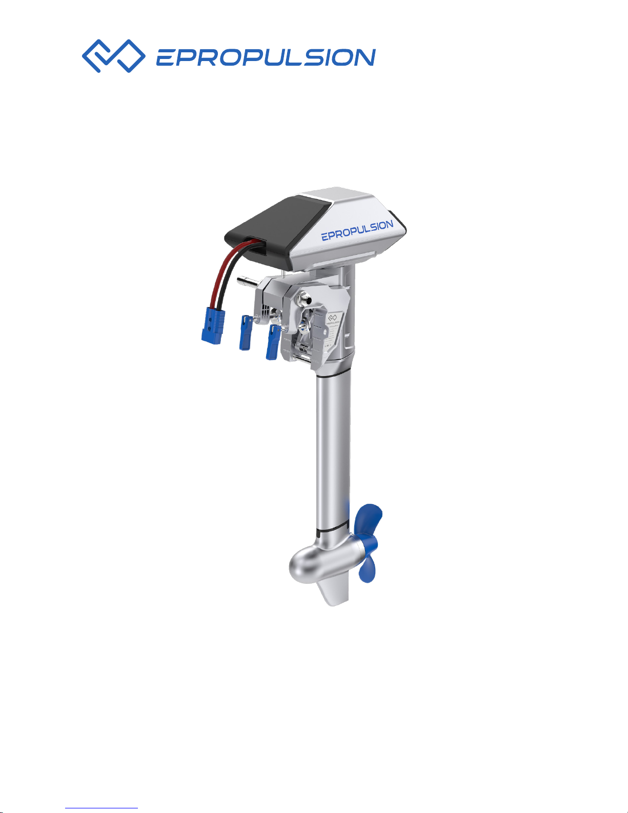
NAVY 3.0 USER MANUAL
November, 2017 Version 1.1
Copyright © 2014-2018 ePropulsion All Rights Reserved
Page 2

Page 3

1
Acknowledgement
Thanks for choosing ePropulsion products, your trust and support in our
company are sincerely appreciated. We are dedicated to providing highperformance electric outboards, as well as thrusters, reliable lithium batteries
and accessories.
Welcome to visit www.epropulsion.com and contact us if you have any
concerns.
Using This Manual
Before use of the product, please read this user manual thoroughly to
understand the correct and safe operations. By using this product, you
hereby agree that you have fully read and understood all contents of this
manual. ePropulsion accepts no liability for any damage or injury caused by
operations that contradict this manual.
Due to ongoing optimization of our products, ePropulsion reserves the rights
of constantly adjusting the contents described in the manual. ePropulsion
also reserves the intellectual property rights and industrial property rights
including copyrights, patents, logos and designs, etc.
This manual is subject to update without prior notice, please visit our website
www.epropulsion.com for the latest version. If you find any discrepancy
between your products and this manual, or should you have any doubts
concerning the product or the manual, please visit www.epropulsion.com.
ePropulsion reserves the rights of nal interpretation of this manual.
This manual is multilingual, in case of any discrepancy in the interpretation
of different language versions, the English version shall prevail.
Symbols
The following symbols will help to acquire some key information.
Important instructions or warnings
Useful information or tips
Page 4
2
Product Identication
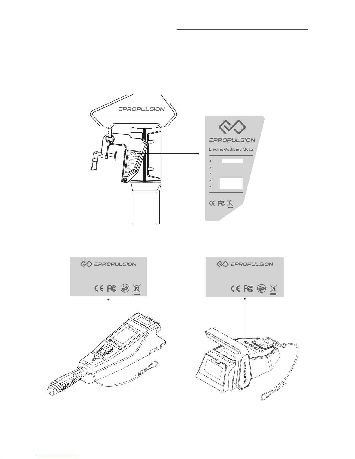
Below picture indicates the serial numbers of NAVY 3.0 main part, NAVY
Tiller Handle and NAVY Remote Control. Please note the position of the
serial numbers and record them for access to warranty service and other
after-sale services.
Rated Power : 3K W
Model:
Rated Power: 3KW
Rated Voltage: 48V
S/N:
Date:
FCC ID:2AKHE-EOM
FCC ID:2AKHE-EOM
Figure 0 -1
Figure 0-2 Figure 0-3
Model: NAVY Tiller Handle
Serial No.: DNTHXXXXXXX
Model: NAVY Remote Controller
Serial No.: DNRCXXXXXXX
Page 5

3
Table of Contents
Acknowledgement .................................................................................. 1
Using This Manual .................................................................................... 1
Symbols .................................................................................................... 1
Product Identication .............................................................................. 2
Table of Contents ..................................................................................... 3
1 Product Overview .................................................................................. 5
1.1 In the Package (R/T) ....................................................................... 5
1.2 Parts and Diagrams ........................................................................ 8
1.3 Specication ................................................................................... 9
1.4 Important Notes ............................................................................. 10
1.5 Declaration of Conformity ............................................................... 11
2 Preparations .......................................................................................... 13
2.1 Selecting the Battery....................................................................... 13
2.2 Mounting the Propeller ................................................................... 14
3 Mounting the Outboard Motor ............................................................. 15
3.1 Position of Mounting .......................................................................15
3.2 Mounting the Outboard ................................................................... 16
3.3 Mounting the Steering System (R) .................................................. 17
3.4 Mounting the Tiller (T) .................................................................... 17
4 Connecting the Battery ........................................................................ 18
4.1 Connecting a 48V Battery ............................................................... 18
4.2 Connecting a NAVY Battery ........................................................... 19
4.3 Batteries in Series/Parallel .............................................................20
5 Remote Control / Tiller .......................................................................... 21
5.1 Displaying .......................................................................................21
5.2 Charging ......................................................................................... 25
5.2.1 Charging by solar power ....................................................................... 25
5.2.2 Charging by wired connection .............................................................. 26
5.3 Power Adjusting .............................................................................. 28
5.3.1 Power Adjusting for Remote Control ..................................................... 28
5.3.2 Power Adjusting for Tiller ...................................................................... 29
Page 6

4
5.3.3 Recalibration ......................................................................................... 30
5.4 Use of Kill Switch ............................................................................ 32
5.5 Pairing Remote Control/Tiller to the Outboard .............................. 32
5.6 Warning Messages ......................................................................... 34
6 Congurations ....................................................................................... 38
6.1 Preference Settings ........................................................................ 38
6.2 Battery Conguration ...................................................................... 38
7 Checklist before Use............................................................................. 41
8 Starting the Outboard ........................................................................... 42
9 Stopping the Outboard ......................................................................... 43
10 Trim Angle Adjusting .......................................................................... 44
11 Maintenance ......................................................................................... 46
11.1 N ot es ............................................................................................. 46
11.2 Maintenance Time Table ............................................................... 46
11.3 Propeller Maintenance .................................................................. 47
12 Transportation and Storage ............................................................... 48
12.1 Transport ....................................................................................... 48
12.2 Placement....................................................................................... 48
12.3 Storage ........................................................................................... 48
13 Emergency Situations ........................................................................ 49
13.1 Collision ........................................................................................ 49
13.2 Sodden Outboard ......................................................................... 49
13.3 Low Battery Level ......................................................................... 49
13.4 Over-temperature Protection ......................................................... 49
14 Warranty .............................................................................................. 50
14.1 Warranty Policies .......................................................................... 50
14.2 Out of Warranty ............................................................................ 51
14.3 Warranty Claim Procedures .......................................................... 51
Page 7
5
1 Product Overview
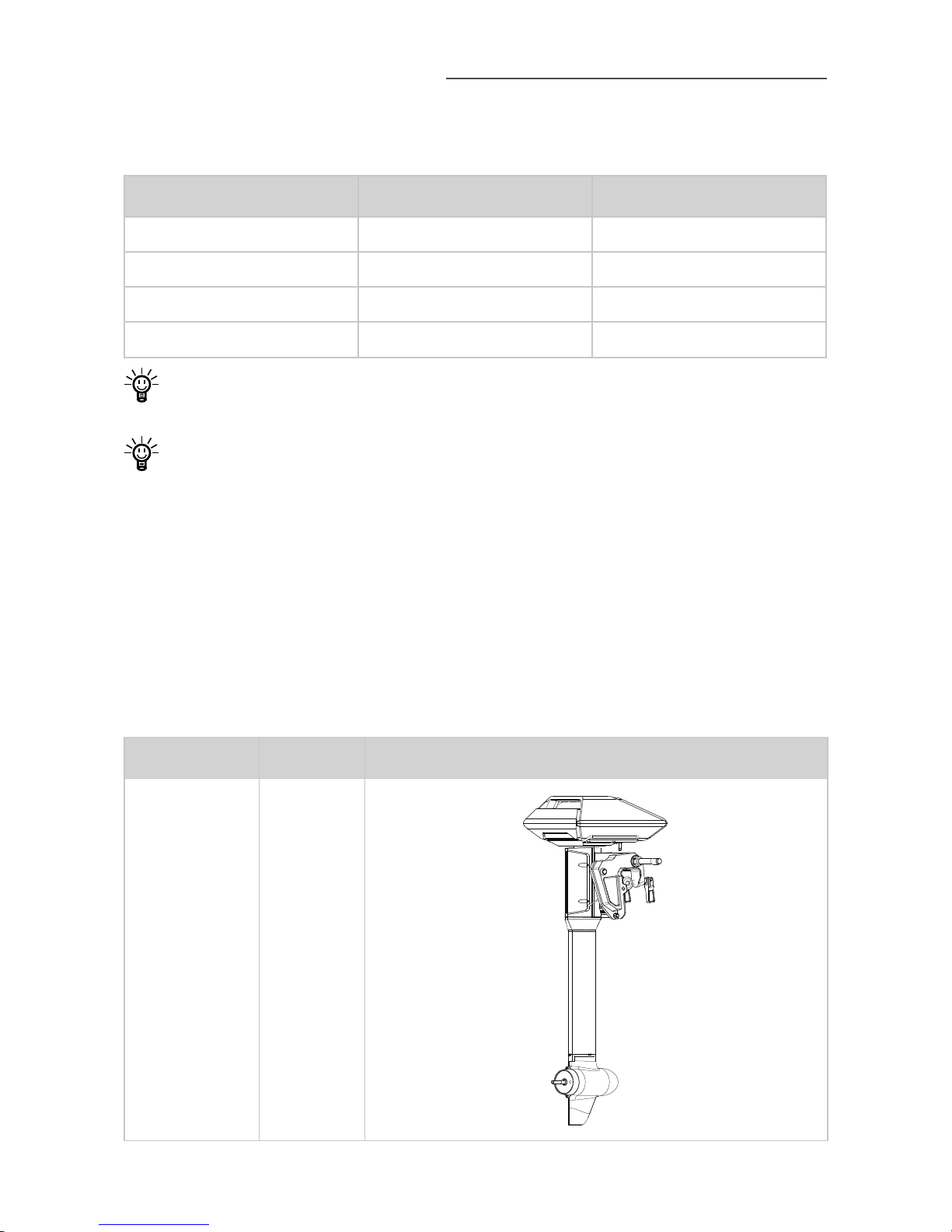
NAVY 3.0 is a 3KW electric outboard motor by either remote control or tiller
control. Below table shows different models of NAVY 3.0.
Model Control Shaft length
NAVY 3.0T-S Tiller 650mm/25.6"
NAVY 3.0T-L Tiller 775mm/30.5"
NAVY 3.0R-S Remote 650mm/25.6"
NAVY 3.0R-L Remote 775mm/30.5"
NAVY 3.0R refers to the remote control version and NAVY 3.0T refers to
the tiller control version.
NAVY 3.0T/R-S refers to the short shaft version, which is recommended
for transom height of 300mm~400mm; NAVY 3.0T/R-L refers to the
long shaft version, which is recommended for transom height of
400mm~500mm.
1.1 In the Package (R/T)
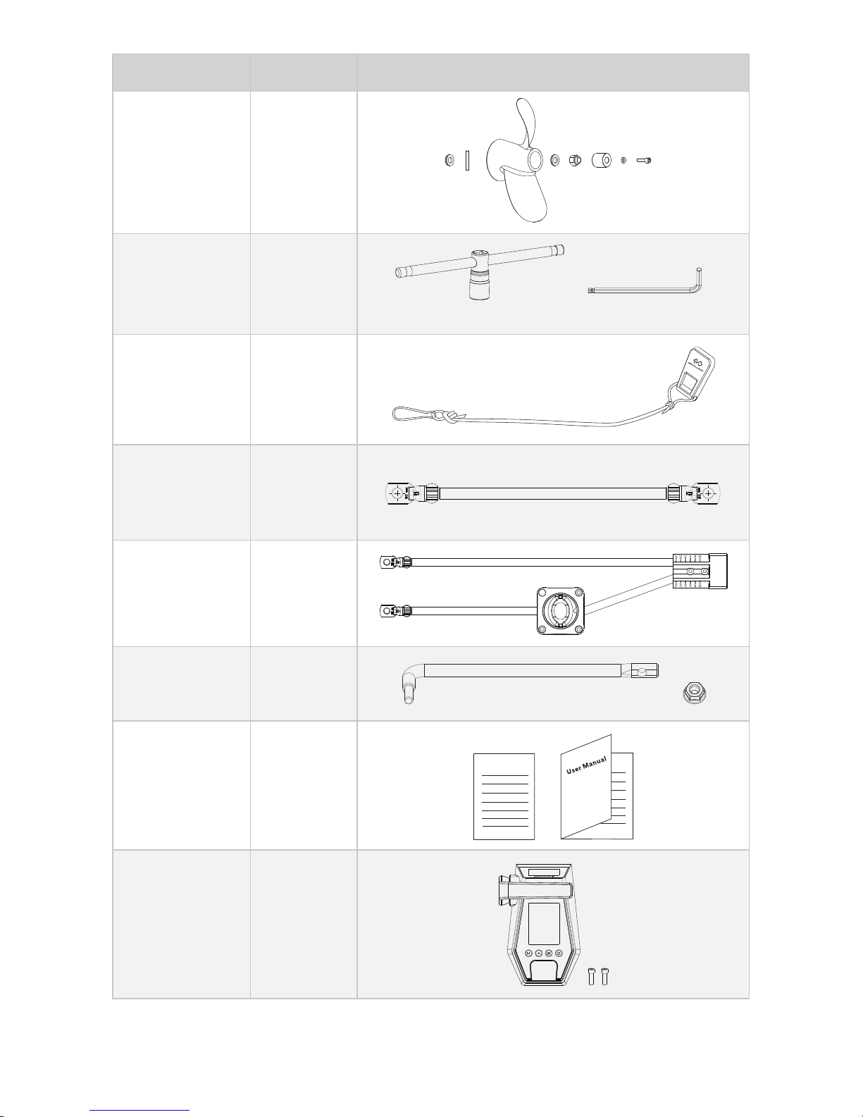
When you receive a set of NAVY 3.0, unpack its package and check if all
the items below are included in the package. If there is any loss or transport
damage, please contact your dealer immediately.
Items Qty./Unit Figure
Outboard
Main Part
1 set
Page 8
6
Items Qty./Unit Figure
Propeller and
Accessories
1 set
Wrench Set 1 set
19mm Wrench M6 Wrench
Kill Switch 2 pieces
Battery
Bridging Cable
3 pieces
Main Switch
Cable
1 piece
Link Arm
(R)
1 set
User Manual
&
Warranty Card
1 set
Warranty
Remote Control
(R)
1 set
Page 9
7
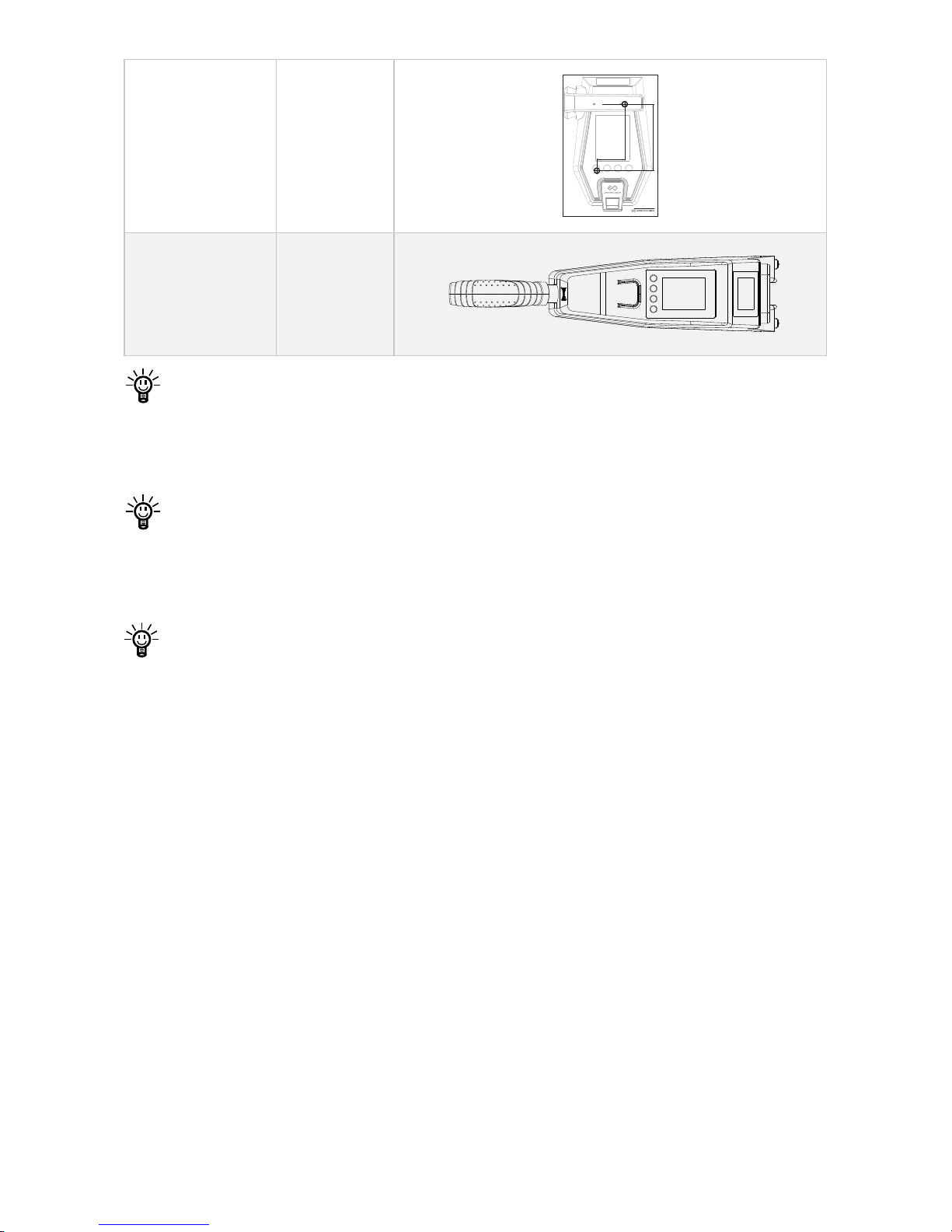
Fixing Guide
(R)
1 piece
41mm
98mm
2× 6mm
Plotting Scale - 1:1
Screw Size - M6×12mm
Navy 6.0R
Fixing Guide
For Remote Controller
Room 702
Kowloon Bldg
555 Nathan Rd
Kowloon, Hong Kong
www.epropulsion.com
Tiller
(T)
1 set
The items marked with “R” are in the package of NAVY 3.0R; and the
items marked with “T” are in the package of NAVY 3.0T; others without
R/T mark are common items included in both NAVY 3.0R package and
NAVY 3.0T package.
Some other accessories are also needed to operate the outboard motor,
such as the battery, charger and communication cable, etc. Users can
buy official accessories such as NAVY Battery, NAVY Charger and
communication cable, etc. from ePropulsion authorized dealers.
Save ePropulsion original package for transport and storage.
Page 10
8
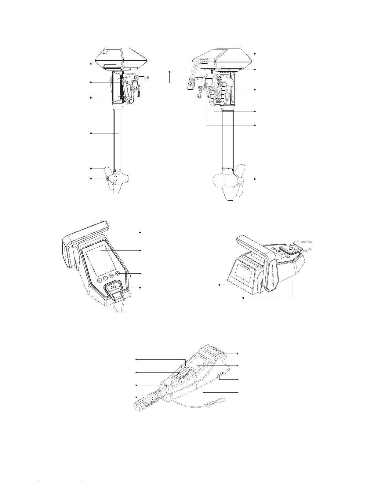
1.2 Parts and Diagrams
Steering
Tube
Release
Button
Trim Lever
Shaft
GPS Module(built-in)
Communication Port
Bracket Clamp
Tightening Handle
for Clamp
Mount Position
of Link Arm
Motor
Power Cable
Connector
Anode
Propeller
Figure 1-1 NAVY 3.0 Main Part
Figure 1-2 Remote Control
Figure1-3 Tiller
Throttle Handle
Buttons
Display Panel
Kill Switch
Communication Port
(Bottom)
Solar Panel
Forward/Reverse Icon
Release Button
Throttle Handle
Display Panel
Buttons
Kill Switch
Communication Port
(Bottom)
Solar Panel
Page 11

9
1.3 Specication
NAVY 3.0S / NAVY 3.0L
Typ e Electric
Rated Voltage / Current 48V / 62.5A
Input Voltage Range 39V ~ 60V DC
Maximum Input Power
(Forward / Reverse)
3KW / 3KW
Comparable Petrol Outboard 6HP
Maximum Overall Efciency 55%
Rated Rotation Speed 2300rpm
Control System Remote / Tiller
Communication Wireless / Wired
Communication Distance ≤10 m
Dimension of Outboard Main Part:
LengxWidthxHeight
413 x 308 x 1075(S) / 1200(L) (mm)
16.2" x 12.1" x 42.3"(S) / 47.2(L)
Dimension of Tiller:
Lx W x H
511mm x 118mm x 100mm /
20.1" x 4.6" x 4"
Shaft Length (S / L) 650mm (25.6") / 775mm (30.5")
Net Weight of Outboard Main Part 22Kg / 48.5lbs(S); 22.6Kg / 49.8lbs(L)
Net Weight of Tiller 1.5Kg / 3.3lbs
Net Weight of Remote Control 0.65Kg / 1.43lbs
Trim Angle Manual 4-step: 0°, 5°, 10°, 15°
Tilt Angle Manual: 60°
Propeller (Diameter / Pitch) 260mm (10.2") / 6.2"
Operating Temperature -25°C ~ 50°C (-13°F ~ 122°F)
Page 12

10
1.4 Important Notes
1. Check the status of the outboard and battery level before each trip.
2. The distance and speed value displayed is measured by Global
Positioning System (GPS), there may exist small errors due to GPS signal
strength degradation or some external environment conditions like
currents, winds and change of course.
3. Ensure the top of outboard is uncovered to avoid GPS signal attenuation.
4. Familiarize yourself with all the outboard operations, including starting,
steering, stopping, trim adjusting and tilting.
5. Only adults who have fully read and understood this manual are allowed
to operate this product.
6. Follow the boat manufacturer’s instructions to choose a suitable outboard.
Do not overload neither the boat nor the outboard.
7. Stop the outboard immediately if someone falls overboard during the trip.
8. Protect the battery from dropping into water or short-circuiting.
9. Follow the battery manufacturer’s instructions and pay attention to short
circuit, over-heat, over-charge and over-discharge.
10. Operate the outboard only when the propeller is underwater.
11. Tilt up the outboard motor above water after use.
12. Wash the outboard in time with fresh water after sailing in salt water.
13. Clean all electronic contacts with contact spray about every two months.
14. Do not leave the outboard in water if the boat is driven by other power
such as sailing or rowing.
15. An error code will display on the panel if the outboard malfunctions. Put
the throttle to zero position and turn off the main switch, then refer to
Chapter 5.6 Warning Messages for details and solutions.
16. For safety consideration, the system will shut down automatically when
the temperature of the motor or driver rise too high or the battery voltage
drops too low during operation.
17. Users are responsible to assemble the propeller and steering wheel. If
other assembly or disassembly is required, please contact your dealer.
ePropulsion accepts no liability for any damage or malfunction caused by
operations that violate this manual.
Page 13

11
1.5 Declaration of Conformity
Object of the declaration:
Product: NAVY 3.0
Model: NAVY 3.0R-S, NAVY 3.0R-L, NAVY 3.0T-S, NAVY 3.0T-L,
NAVY 3.0P, NAVY 3.0C
Company Name: Dongguan ePropulsion Intelligence Technology Limited
Company Address: Room 202, Bldg.17A, Headquarter No.1, 4th XinZhu
Road, SongShan Lake District, Dong Guan, Guang Dong, China
The object of the declaration is in conformity with the following directives:
EMC-directive 2014/30/EU
MD-directive 2006/42/EC
RED Directive 2014/53/EU
Applied standards:
EN 55014-1:2006+A1:2006+A2:2011
EN 55014-2:2015
EN 61000-3-2:2014
EN 61000-3-3:2013
EN 60204-1: 2016
EN ISO 12100:2010
EN 301 489-3: 2002 V1.4.1
EN 301 489-1:2008 V1.8.1
CE Test Report NO.: ATT1709040251D, ATT1709040251E,ATT1709040251M
Issued Date: September 30, 2017
The original certicates were issued by
Shenzhen An-Teng Testing Service Co., Ltd. in Shenzhen, China.
This device complies with part 15 of the FCC Rules: Operation is subject to
the following two conditions:
(1) This device may not cause harmful interference and,
(2) This device must accept any interference received, including
interference that may cause undesired operation.
FCC Test Report NO.: GTS201709000032E01
Issued Date: July 05, 2017
Page 14

12
FCC Statement
This equipment has been tested and found to comply with the limits for a
Class B digital device, pursuant to Part 15 of the FCC Rules. These limits
are designed to provide reasonable protection against harmful interference
in a residential installation. This equipment generates uses and can radiate
radio frequency energy and, if not installed and used in accordance with
the instructions, may cause harmful interference to radio communications.
However, there is no guarantee that interference will not occur in a particular
installation. If this equipment does cause harmful interference to radio or
television reception, which can be determined by turning the equipment off
and on, the user is encouraged to try to correct the interference by one or
more of the following measures:
-- Reorient or relocate the receiving antenna.
-- Increase the separation between the equipment and receiver.
-- Connect the equipment into an outlet on a circuit different from that to
which the receiver is connected.
-- Consult the dealer or an experienced radio/TV technician for help.
The manufacturer is not responsible for any radio or TV itnerference caused
by unauthorized modications to this equipment. Such modications could
void the user's authority to operate the equipment.
Signed by :
Shizheng Tao, Chief Executive Ofcer & Cofounder of
Dongguan ePropulsion Intelligence Technology Limited
Page 15

13
2 Preparations
2.1 Selecting the Battery
Lithium-based and lead-acid batteries can be used to supply power for
NAVY 3.0. Considering the high performance in energy density and
discharge ability, lithium-based batteries are more preferable. To ensure that
NAVY 3.0 can work at its full power continually, the batteries are required
to possess over 62.5A of continuous discharge current. To ensure longer
operating duration, the battery capacity is recommended to be 3000Wh or
above.
The rated continuous discharge current is affected by the battery type and
quantity of parallel batteries. To use lead-acid batteries, conventional leadacid or AGM or GEL batteries are acceptable, while starter batteries are not
recommended. Traction batteries or deep cycle batteries are more preferable
as they give power over sustained period of time. Besides, the deep cycle
marine batteries are also capable.
Battery capacity is a major factor that affects trip duration and distance.
For instance, a battery with 48V of rated voltage completely discharges at
a continuous current of 62.5A in 1 hour, so its rated capacity is 3000Wh
(62.5Ah*48V=3000Wh), we also can say its rated capacity is 62.5Ah. The
maximum power of NAVY 3.0 is 3KW which means the system can be
running at full power for about 1 hour when using this battery. You can select
a battery with proper capacity based on your requirements for travelling time
and distance. Note that the operating time and distance are also affected
by the input power of the outboard plus the external environment and
temperature. In addition, the type and tonnage of boats also play important
roles.
Users can choose NAVY Battery designed by ePropulsion for NAVY
outboard motors, which is a type of Lithium-ion battery with 3000Wh
capacity. When using with NAVY 3.0, one or more sets of NAVY Batteries
are required. When more than one NAVY Batteries are used in parallel,
communication cables should be used to connect NAVY batteries and NAVY
3.0 outboard motor for internal information exchange.
Users can connect four 12V batteries in series to make a 48V battery set
and use it to supply power for NAVY 3.0. Users can also enlarge the battery
capacity by parallel conguration.
Page 16
14
When using NAVY Batteries, the batteries will work well once being
correctly connected. When using non-ePropulsion batteries, before
starting the outboard, users should configure the batteries via the
Remote Control for the rst time use, otherwise the batteries may not
work properly.
Only use the same batteries (same model, same capacity, same age
and same manufacturer) in series or in parallel conguration. Variations
in the batteries will cause damage to them.
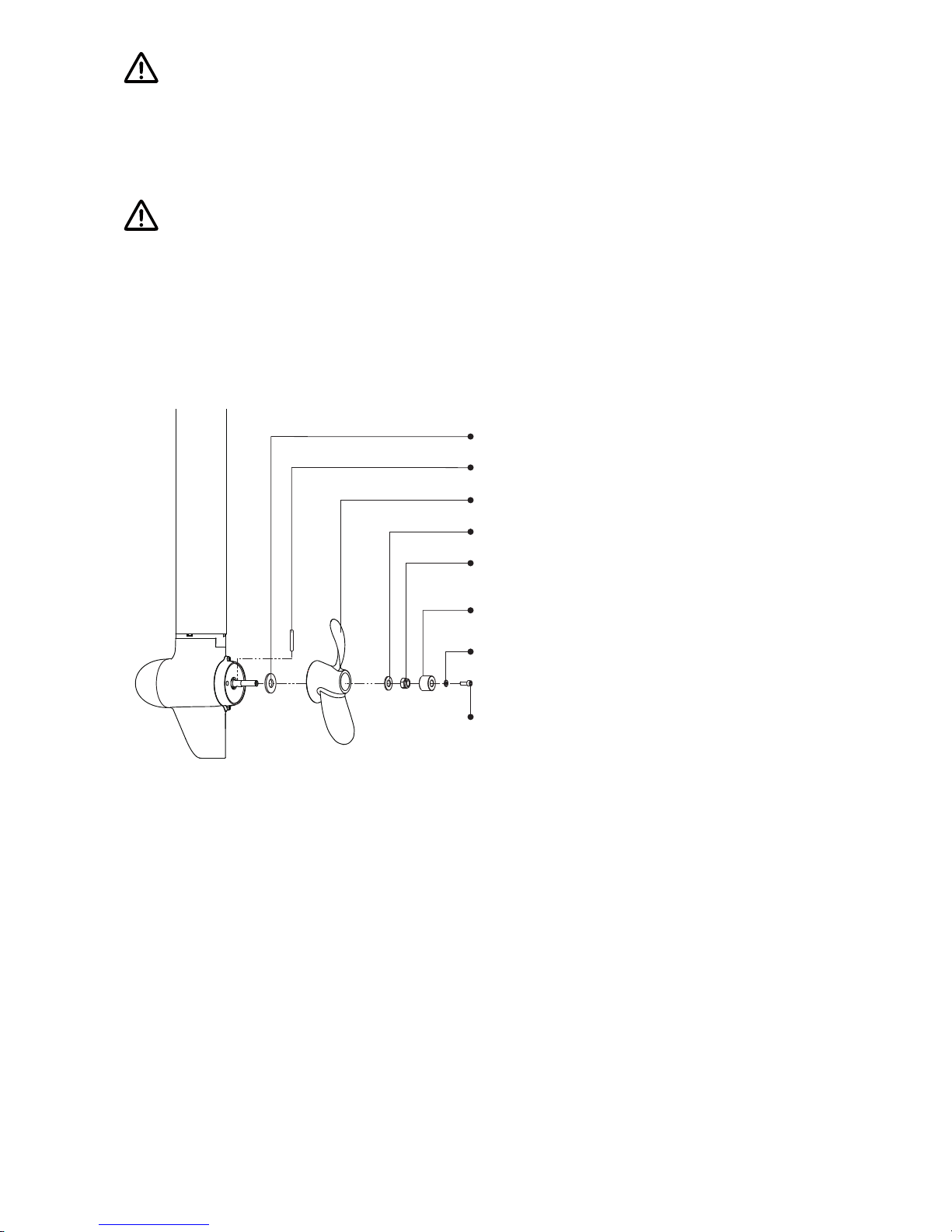
2.2 Mounting the Propeller
Figure 2-1 displays how to mount a propeller correctly.
Step3: Attach the propeller.
Step4: Attach the Φ12 washer.
Step5: Tighten the nut with 19mm (3/4 inch)
socket wrench.
Step6: Attach the Anode.
Step1: Attach the Φ16 washer.
Step8: Screw and tighten the nut
with M6 hexagon wrench.
Step2: Fix the pin to the hole of shaft.
Step7: Attach the Φ6 washer.
Figure 2-1
Page 17
15
3 Mounting the Outboard Motor
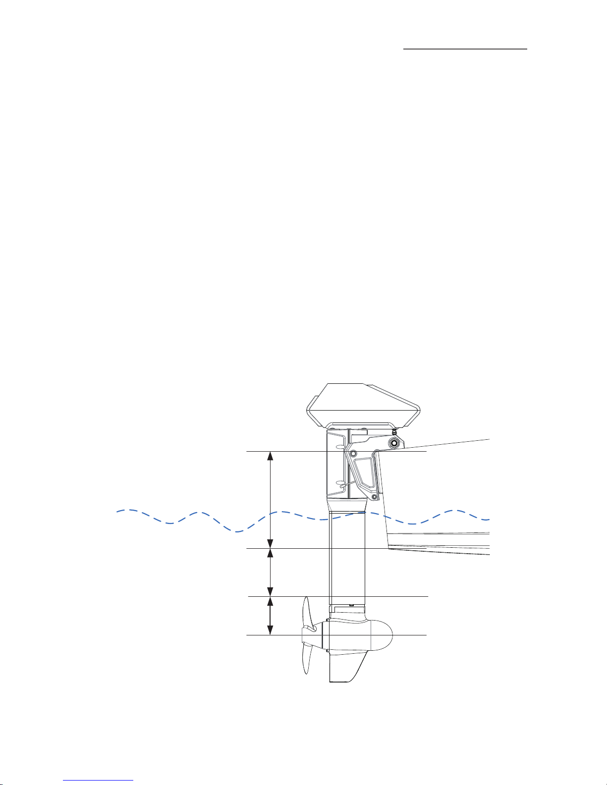
Select an outboard with proper shaft length according to the transom height
of your boat. The top of the propeller should be 100mm to 150mm below the
bottom of the boat.
The outboard should be mounted on the centerline of your boat. If the boat
shape is asymmetric, please consult your dealer for proper solution.
3.1 Position of Mounting
The mounting height of the outboard affects the running speed seriously.
When the mounting height is too high, cavitation may occur, which may
lead to speed slowdown, energy waste, and propeller damage. When the
mounting height is too low, the water resistance will increase reduction in
both travelling speed and power efciency.
In general, the optimal mounting height is affected by the specic conditions
of a boat. In order to get the optimal mounting height, it’s suggested to test
running by mounting the outboard at different heights. Please consult your
dealer for more information.
R=130mm
150mm≥H≥100mm
Transom Height
450mm≥H≥350mm
Figure 3-1 NAVY 3.0-Shortshaft
Page 18
16
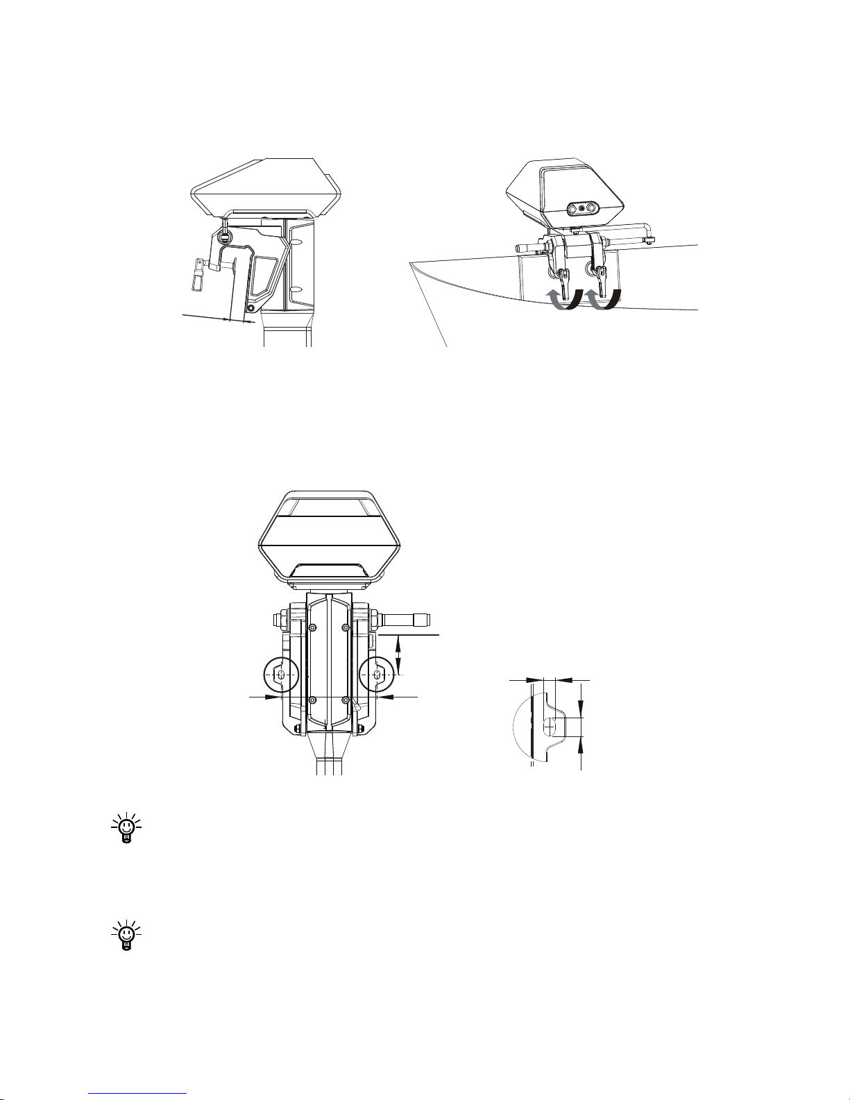
3.2 Mounting the Outboard
Method 1
Rotate the two clamps in clockwise direction to x the outboard onto transom.
30~70mm
Lock
Figure 3-2 Figure 3-3
Method 2
Use two screws to x the outboard to the boat. The dimensions of the two
mounting Wholes are shown below.
16mm
10mm
Top of boat transom
175mm
86mm
Figure 3-4
Ensure the outboard is firmly fixed as loosened clamp screws may
cause the outboard to fall into water or get damaged. Check the screws
or clamps every time before use since they may be loosened because
of mechanical vibrations.
A cable is recommended to be used to avoid complete loss of your
outboard in case it falls off the transom. Use the cable to connect your
outboard and a secure mounting point on the boat.
Page 19
17
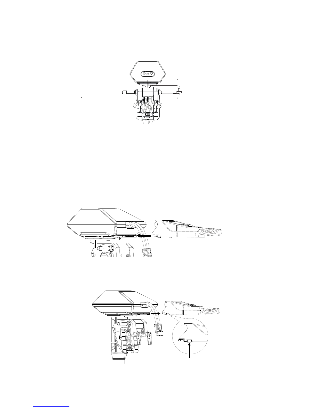
3.3 Mounting the Steering System (R)
When using the Remote Control, please prepare a steering wheel (not
supplied with NAVY 3.0) and mount it on the corresponding position to
control the direction.
Step2: Mount the Link arm with
two M8 nuts.
Step3: Fasten the steering wheel
shaft on the steering tube
with thread.
Step1: Insert the steering wheel
shaft into the steering tube.
Figure 3-5
3.4 Mounting the Tiller (T)
In the package of NAVY 6.0T, the Tiller is not mounted on the outboard
motor prior to delivery. Users can mount it by one simple step:
Align the Tiller to the mounting recess of the outboard motor in the direction
of the arrow and plug in the Tiller until a click sound is heard.
Not to jam the outboard calbe
while mounting the tiller.
Figure 3-6
To detach the Tiller: press the release buttons (Figure 3-7) on both sides of the Tiller
and plug it out.
Figure 3-7
Release Button
Page 20
1818
4 Connecting the Battery
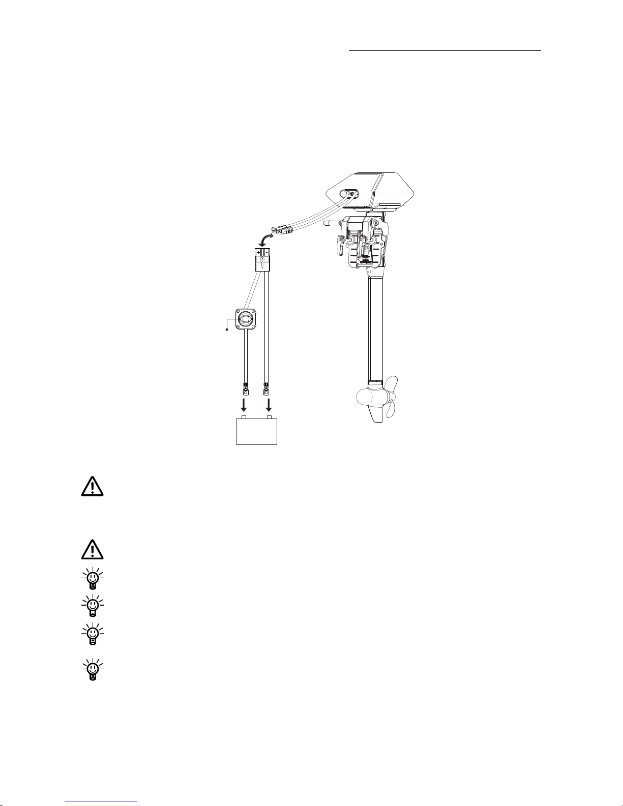
4.1 Connecting a 48V Battery
When using a battery, make sure the main switch is off before connection.
①
Connect the main switch cables to the battery.
②
Connect the main switch cables with the power cables from the outboard.
Main
Switch
①
②
+ -
48V
+ -
Figure 4 -1
When using non-NAVY batteries, users should congure the batteries
via Remote Control/Tiller for the rst time use, otherwise the batteries
may not work properly.
Avoid battery short-circuit during connection.
Outboard motor will stop working once the power cable disconnects.
Clockwisely rotate the main switch to power on the battery before use.
Users can also enlarge the battery capacity by connecting multiple
batteries in parallel.
The main switch and power cable are connected by the xing screws
that may loosen after long-time use. Loosen screws will lead to poor
contact. If this problem is discovered, open the back cover of the main
switch, and tighten the screws inside.
Page 21
19
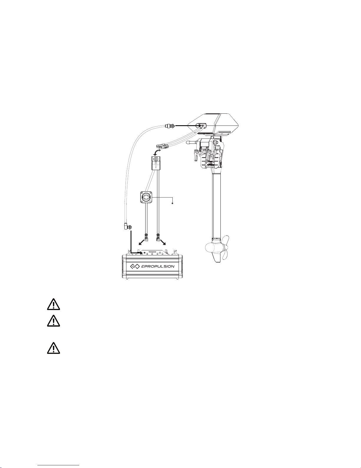
4.2 Connecting a NAVY Battery
When using a NAVY Battery, make sure the main switch is off before
connection.
①
First connect the main switch cables to the NAVY Battery.
②
Connect the main switch cables with the power cables from the outboard.
③
Connect NAVY 3.0 outboard motor to the NAVY Battery with the
communication cable.
+ -
Main
Switch
①
②
③
③
+ -
Figure 4-2
Avoid battery short-circuit during connection.
Outboard motor will stop working once the communication cable or
power cable disconnects.
Use communication cables to connect NAVY Batteries when multiple
NAVY Batteries are used in parallel.
Page 22
20
Clock-wisely rotate the main switch to power on the battery before use.
Users can also enlarge the battery capacity by connecting multiple
batteries in parallel.
The main switch and the power cable are connected by the fixing
screws that may loosen after long-time use. Loosen screws will lead to
poor contact. If this problem is discovered, open the back cover of the
switch, and tighten the screws inside.
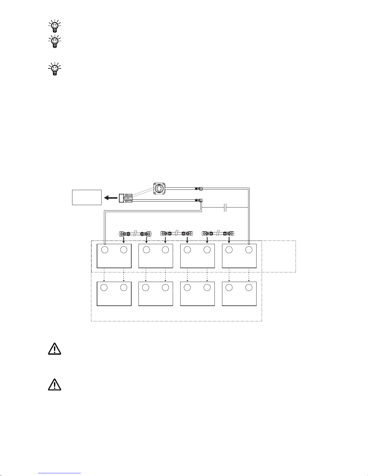
4.3 Batteries in Series/Parallel
When connecting four 12V batteries in series to make a 48V battery set
to supply power for NAVY 3.0, use bridging cables to connect batteries in
series (Figure 4-3). Make sure to connect the main switch cable to battery
positive terminal and the other cable to battery negative terminal.
-
+
12V
-
+
12V
-
+
12V
-
+
12V
- +
12V
- +
12V
- +
12V
- +
12V
Parallel
Connection
Serial
Connection
Bridging
Cable
Bridging
Cable
Bridging
Cable
48V
Outboard
Motor
Figure 4-3
Only use the same batteries (same model, same capacity, same age
and same manufacturer) in series and/or in parallel. Variations in
batteries will cause damage.
Never reverse the polarity. Please pay more attention when connecting
batteries in series and/or in parallel conguration. Always double check
by referring to Figure 4-3.
Page 23
21
5 Remote Control / Tiller
The Remote Control/Tiller is used for starting and stopping the NAVY
outboard motor, adjusting the speed of the motor, configuring the battery
parameters, displaying the system information and messages, etc. The
Remote Control/Tiller is powered by either solar power or the built-in lithium
battery. Both Remote Control and Tiller wirelessly communicates with the
outboard control system built in the main outboard motor. The only functional
difference between Remote Control and Tiller is the steering method
: t
he
Tiller itself owns the steering capability, while the Remote Control requires
an additional steering wheel to help steer.
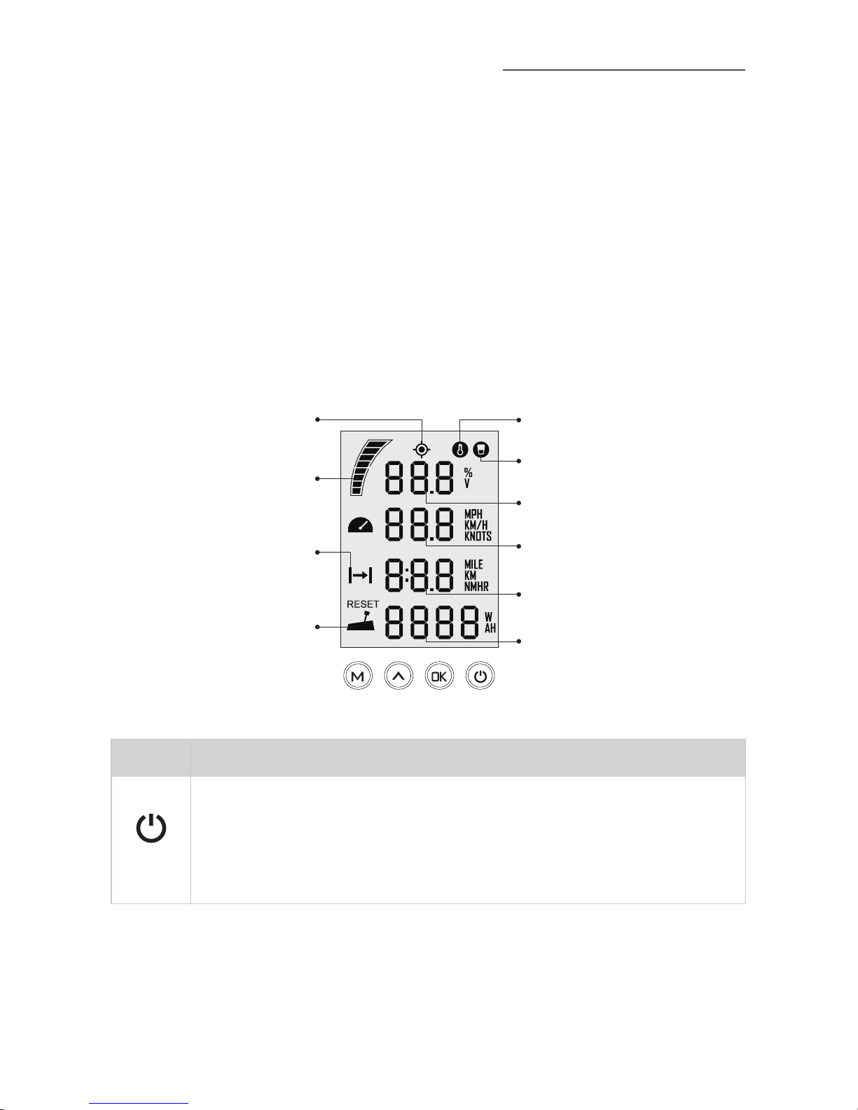
5.1 Displaying
Battery Level Indicator
Throttle Reset Indicator
Battery Level/Voltage
Kill Switch Status Indicator
Overheat Alert
Current Speed
Distance/Time
Throttle Power
GPS Status Indicator
Travelled Distance/
Time or Remaining
Distance/Time
Figure 5 -1
Buttons Functions
“Power”
1. In power-off state, press and hold the power button to power
on the Remote Control/Tiller.
2. In power-on state, press and hold the power button to power
off the Remote Control/Tiller.
Page 24
22
Buttons Functions
“OK”
1. On setting pages, press " " button to save the current
settings and switch to the next item.
2. On setting pages, press and hold “ ” button, and the
system will save your settings, the display will exit from
setting page and return to the home page.
3. In power-on state, when home page displays or all the
characters display on the page, press “ ” butto n
and hold 5s to enter the Remote Control pairing page.
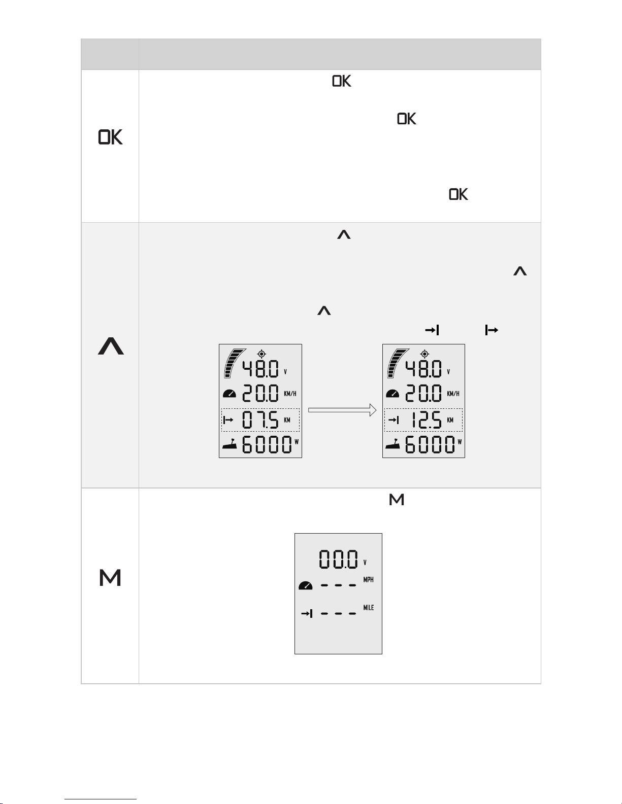
“Up”
1. On any setting page, press “
” button to view options for
current setting.
2. In power-on state, when home page displays, press “
”
button and hold 10s to enter the throttle calibration page.
3. On home page, press “
” button to switch the travelling
distance or time displaying icon between “ ” and “ ”.
press
“Up”
button
Main page 1 Main page 2
“Menu”
1. In power-on state, press and hold “ ” button to enter the
preference setting page.
Preference setting page
Page 25
23
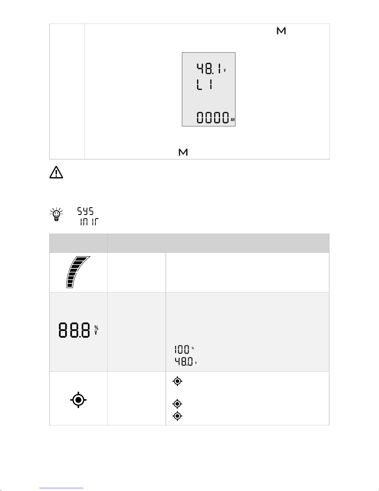
2. On preference setting page, press and hold “ ” button to
enter the battery setting page.
Battery setting page
3. On any page, press “ ” button to return home page.
If users enter the page without setting any parameters, the current
parameters displayed on the page will be saved as user parameters by
default.
If “ ” shows on start-up, it indicates system initialization.
Icons Functions
Battery level
indicator
Indicating approximate battery level. The
solid blocks stand for remaining battery.
Battery level/
voltage
Indicating accurate current battery level
percentage/battery voltage, is congurable
in preference setting page.
For example:
: indicates current battery level.
: indicates current battery voltage.
GPS status
indicator
Hidden: no satellite signal is received
or GPS does not work.
Blink: GPS is connecting to satellites.
Shown constantly: GPS is in use.
Page 26
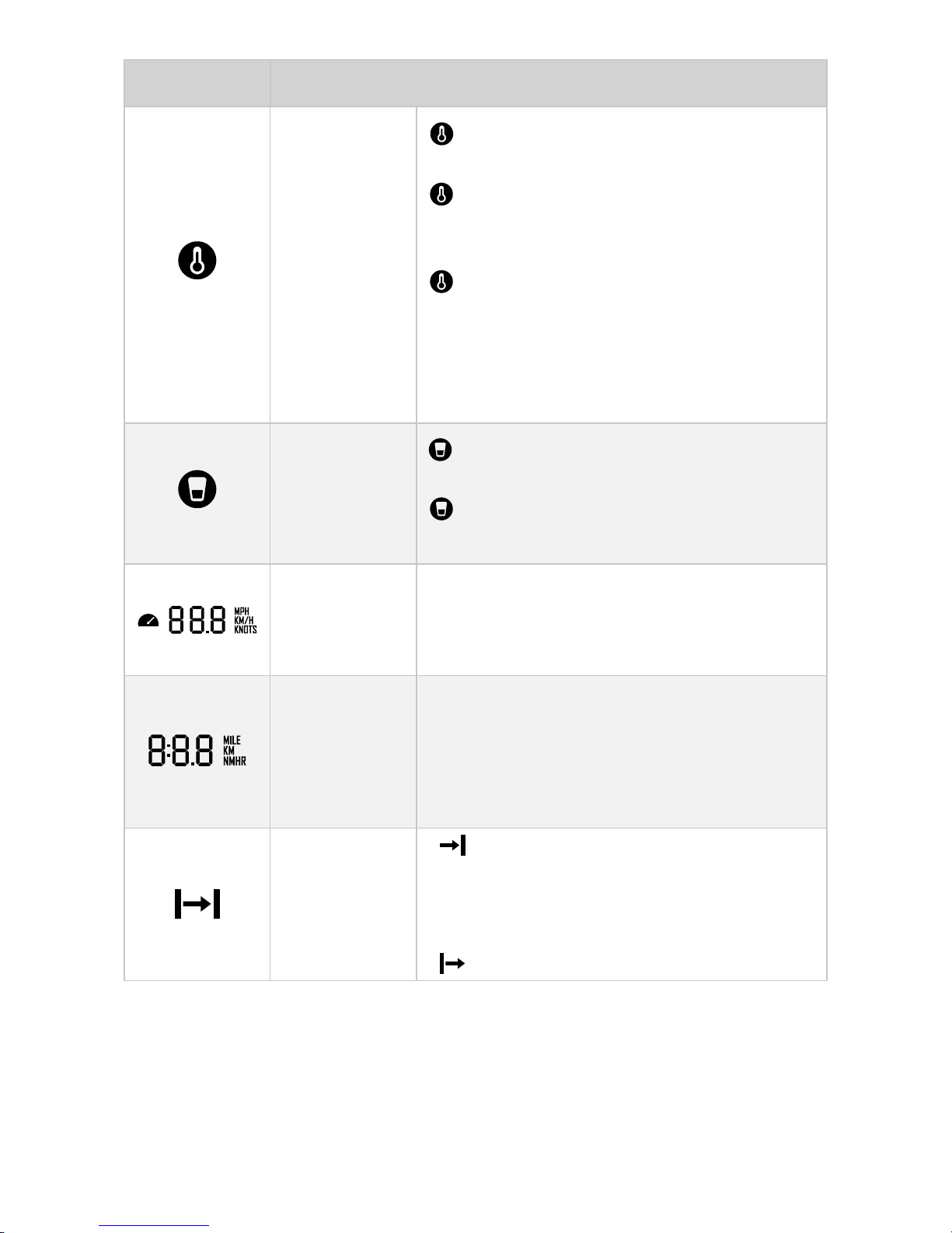
24
Icons Functions
Over-heat alert
Hidden: system temperature is in
normal range.
Blink: system temperature is a little
high and the maximum input power of
motor has been lowered than 3KW.
Shown constantly: system is over
temperature and the outboard will
stop working. The outboard motor
can’t be started until the system
temperature drops to a certain level.
Kill switch
status indicator
Hidden: kill switch is present and is
working well.
Shown constantly: the kill switch is
detached.
Current speed
Displaying real time cruising speed.
Set units (KM/H,MPH or KNOTS) in
preference setting page.
Distance/time
display
Displaying real time travel distance/time.
Set units (MILE, KM (kilometer) and NM
(nautical mile)) in preference setting page.
The time unit is HR (hour).
Travelled
distance/time
or remaining
distance/time
: Remaining distance or time that
outboard can travel.
Set units (MILE, KM (kilometer) and NM
(nautical mile)) in preference setting page.
: Travelled distance or time.
Page 27
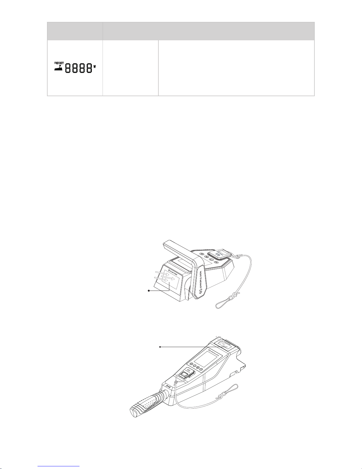
25
Icons Functions
Throttle Power
Displaying real time input power to the
system.
A blinking “RESET” indicating the throttle
should be reset to zero position.
5.2 Charging
Both the Remote Control and Tiller have a built-in lithium battery for power
supply. The battery will be charged automatically under normal use: get
charged by solar power or wired connection.
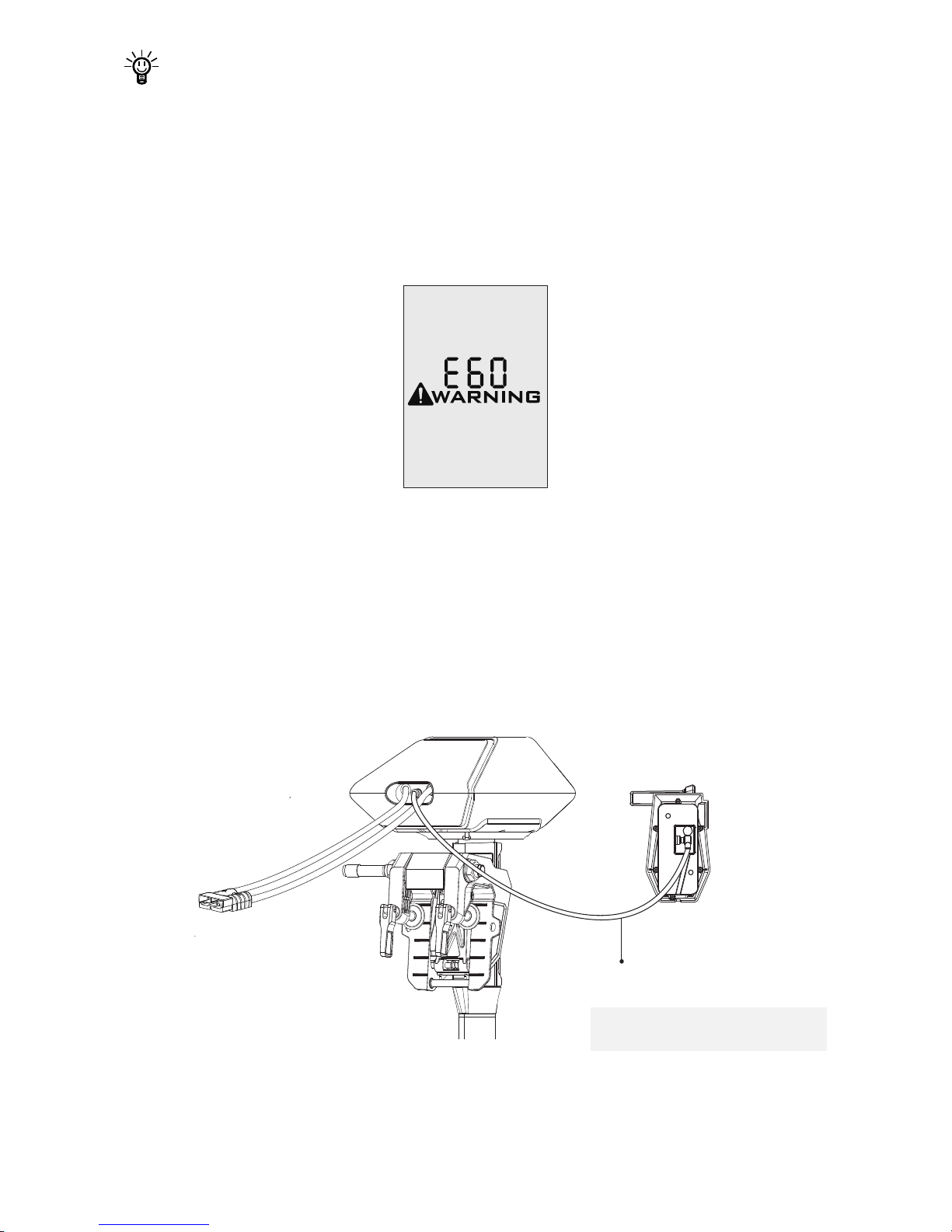
5.2.1 Charging by solar power
When the solar panel receives enough sunshine, it will generate electricity to
charge the built-in lithium battery. While charging the battery by solar power,
it’s suggested to face the solar panel of the Remote Control/Tiller toward
sunlight to get better charging effect.
(Face the Sun)
Solar Panel
Figure 5-2
Figure 5-3
(Face the Sun)
Solar Panel
Page 28
26
It’s recommended to charge the Remote Control/Tiller by solar power.
5.2.2 Charging by wired connection
If the Remote Control/Tiller can’t get enough solar power for a long time, the
battery level will run out. In this case, a warning message with an error code
E60 (Figure 5-4) will display on the LCD panel to remind you to charge the
Remote Control/Tiller.
Figure 5-4
Please follow the below steps to charge the Remote Control/Tiller by wired
connection.
First, connect the Remote Control/Tiller to the outboard motor by a
communication cable rst (Figure 5-5/Figure 5-6);
Then, connect the outboard motor to the battery.
Communication Cable
Figure 5-5
* The communication cable needs
to be purchased separately.
Page 29
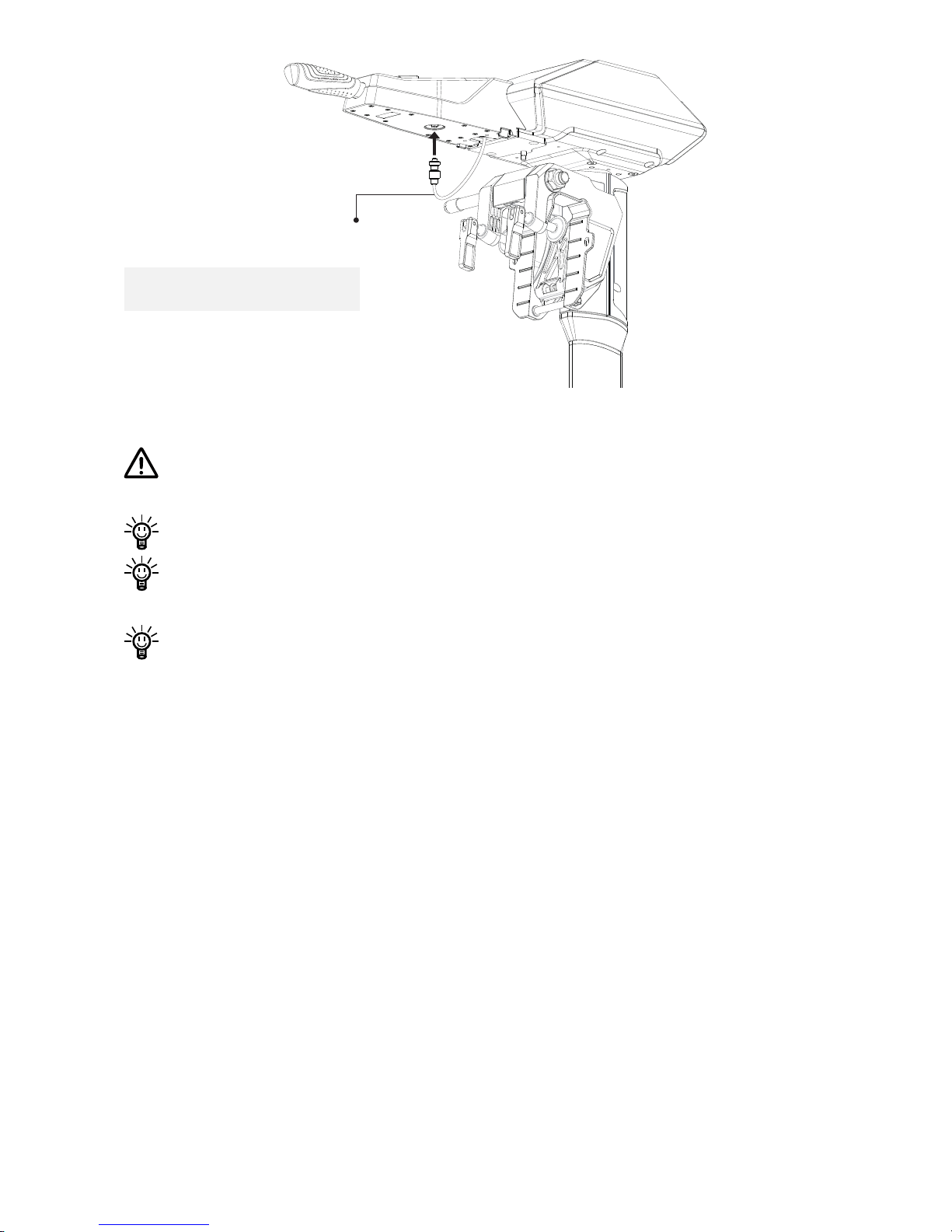
27
Communication Cable
Figure 5-6
During long-term storage, ensure to charge the Remote Control/Tiller
battery every 6 months to avoid over-discharge.
After long-term storage, charge the Remote Control/Tiller before use.
The communication cable is not included in this package. Please
purchase one from your dealer if you choose this charging method.
It’s recommended to switch off the Remote Control/Tiller while
connecting the communication cable. When the Remote Control/Tiller
is switched on while charging, as the outboard main part and Remote
Control/Tiller are in communication, the working outboard motor will
stop once the communication cable disconnects.
* The communication cable needs
to be purchased separately.
Page 30
28
5.3 Power Adjusting
5.3.1 Power Adjusting for Remote Control
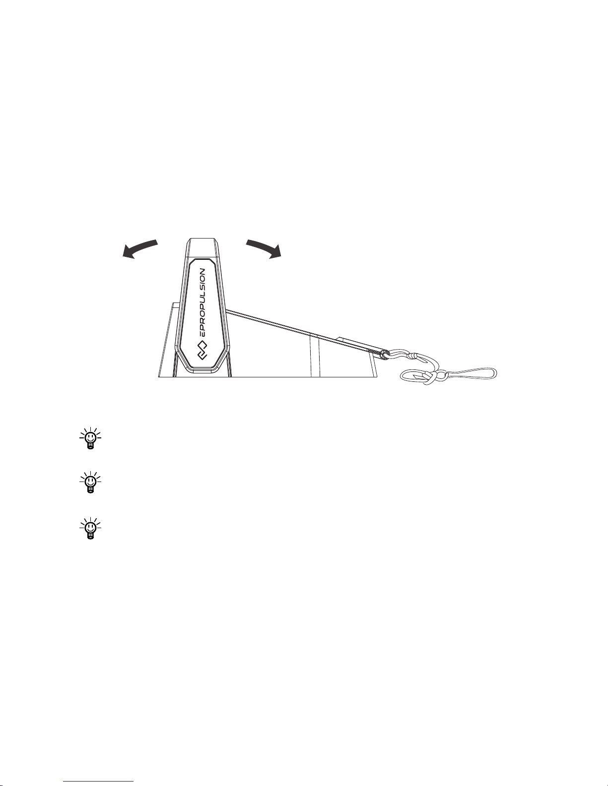
The Remote Control is mainly used to adjust the input power of the outboard
motor. When the battery is well connected and switched on, power on the
Remote Control to start the outboard, then slowly push the throttle forward
position to increase the throttle power. The maximum forward/backward
power is 3KW.
Forward Neutral Backward
3KW 3KW
Figure 5-7
Before power on the Remote Control, please reset the throttle to neutral
position.
If you nd a blinking “RESET” on the display panel, you are reminded to
reset the throttle to neutral position.
If you turn the throttle from the forward position to the backward position
directly, the motor will rst stop shortly, then start turning to the reverse
direction.
Page 31
29
5.3.2 Power Adjusting for Tiller
The Tiller is mainly used for power adjusting and steering control. When
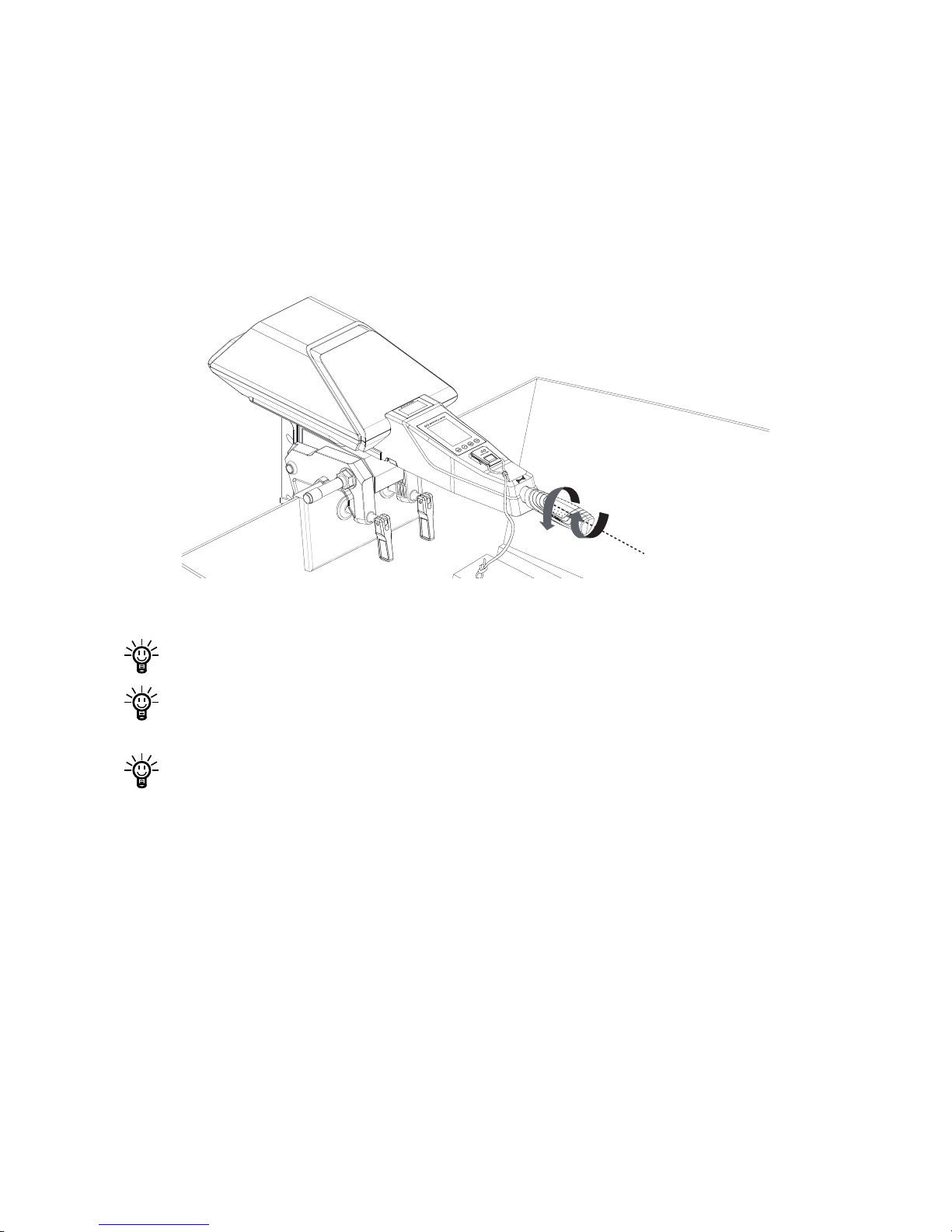
the battery is well connected and switched on, power on the Tiller
to start the outboard, then turn the throttle gradually form zero position to the
forward direction to start. Please refer to Figure 5-8. Change the heading
direction by turning the Tiller on horizontal level. The maximum forward/
backward power is 3KW.
Forward
Backward
Neutral
Figure 5-8
Before power on the Tiller, please reset the throttle to neutral position.
If you nd a blinking “RESET” on the display panel, you are reminded to
reset the throttle to neutral position.
If you turn the throttle from the forward position to the backward position
directly, the motor will rst stop shortly, then start turning to the reverse
direction.
Page 32
30
5.3.3 Recalibration
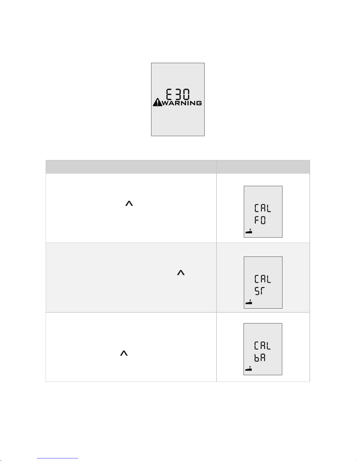
The throttle position sensor should be recalibrated if the below error code
displays.
Figure 5-9
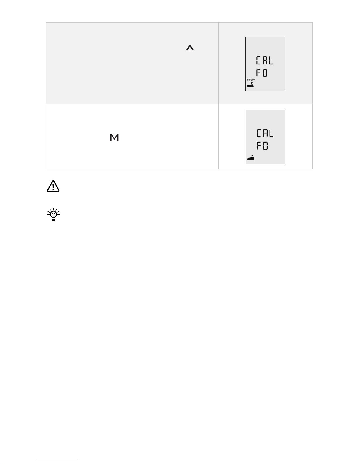
Recalibration process LCD Displaying
Step1: Long press “
” button for 10s until
“CAL FO” displays.
Step2: Push/Turn the throttle to the maximum
forward power position, then press “
”
button. “CAL ST” will display and “CAL” will
be blinking.
Step3: Pull/Turn the throttle to the middle
(zero) position where you can hear a click
sound, then press “
” button, “CAL bA” will
display and “CAL” will be blinking.
Page 33
31
Step4: Pull/Turn the throttle to the maximum
backward power position, then press “
”
button. “CAL FO” will display and calibration
is completed. A blinking “RESET” will display
to remind you to reset the throttle to zero
position.
Step5: Push/Turn the throttle to zero position
and press the “ ” button and return to the
main page.
Carry out the throttle calibration procedures strictly as the above
sequence.
When recalibrating a Remote Control, please pull/push the throttle.
When recalibrating a Tiller, please turn the throttle.
Page 34
32
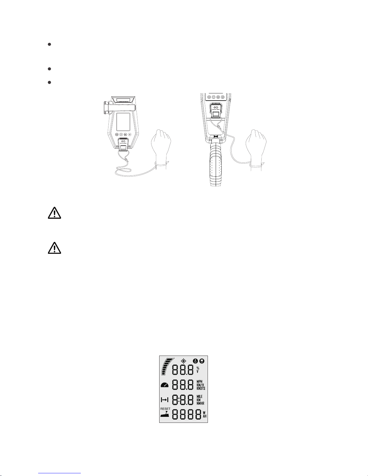
5.4 Use of Kill Switch
Locate the kill switch to the right place on the Remote/Tiller and tie its
lanyard to your wrist or life jacket.
Stop the outboard in emergency by detaching the kill switch.
To run the motor again, rst attach the kill switch then start the motor.
Figure 5-10 Figure 5-11
The kill switch generates magnetic eld. Keep it 50cm / 20inches away
from medical implants like pacemakers and magnetic cards (e.g. credit
card) as well as other magnetic media.
The magnetic eld of the kill switch may interfere with some electronic
instruments. Keep it away from these electronic instruments.
5.5 Pairing Remote Control/Tiller to the Outboard
The Remote Control/Tiller and NAVY outboard are paired before packing.
However, if the Remote Control/Tiller or the outboard is replaced with a new
one, the original wireless link will break and wireless communication failure
will occur. The main page of the LCD panel on the Remote Control/Tiller will
display as below. In this case, users should conduct pairing again.
Figure 5 -12
Page 35
33
However, if the Remote /Tiller or the outboard motor is not replaced, but
the LCD panel still displays like this, you should check and:
1) Make sure the Remote is not far from the outboard motor;
2) Make sure all the equipment involved is normally powered on.
If the Remote /Tiller still displays like Figure 5-12 after check, it indicates
an error has occurred. Please contact your dealer for repair.
There are two pairing methods. Please choose one proper method and
follow the procedures.
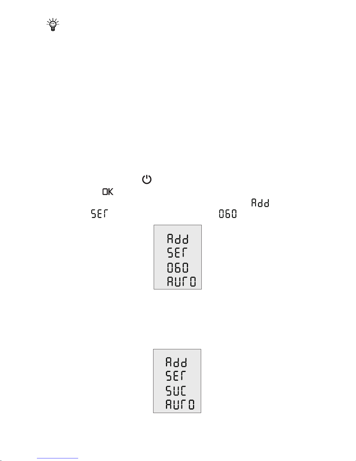
a. Wireless Automatic Pairing
Step1: Switch off both NAVY outboard and Remote Control/Tiller.
Hold the remote within 0.5m to the head part of the outboard,or
mount the tiller to the outboard.
Step2: Pess and hold the “ ” button on the Remote or Tiller to switch on.
Step3: Press “ ” button and hold 5s to enter the pairing setting page
(Figure 5-13). On this page, you can nd blinking “ ” (address)
and “ ” (set), and a countdown timer “ ” (60s).
Figure 5 -13
Step4: Switch on NAVY power. Wait for them to get paired in a few seconds.
Step5: After pairing, the LCD screen will display as Figure 5-14 for 5s, then
returning to home page automatically.
Figure 5 -14
Page 36
34
If pairing fails within 60s, go back to Step3 and try again.
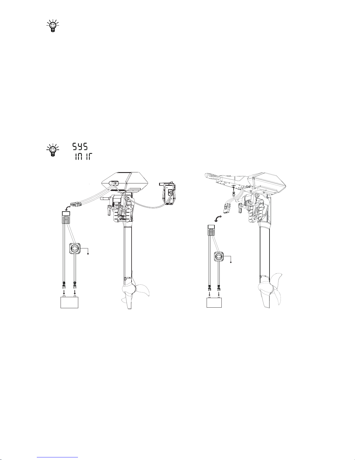
b. Wired Automatic Pairing
Step1: Switch off both NAVY outboard and Remote Control/Tiller.
Step2: Connect NAVY outboard and Remote Control/Tiller with a
communication cable. Please refer to Figure 5-15 or Figure 5-16.
Step3: Switch on both NAVY outboard and Remote Control/Tiller
and wait for them to get paired.
Step4: Pairing succeeds until home page displays. Then disconnect the
communication cable.
If “ ” shows on start-up, it indicates system initialization.
Figure 5-15 Figure 5-16
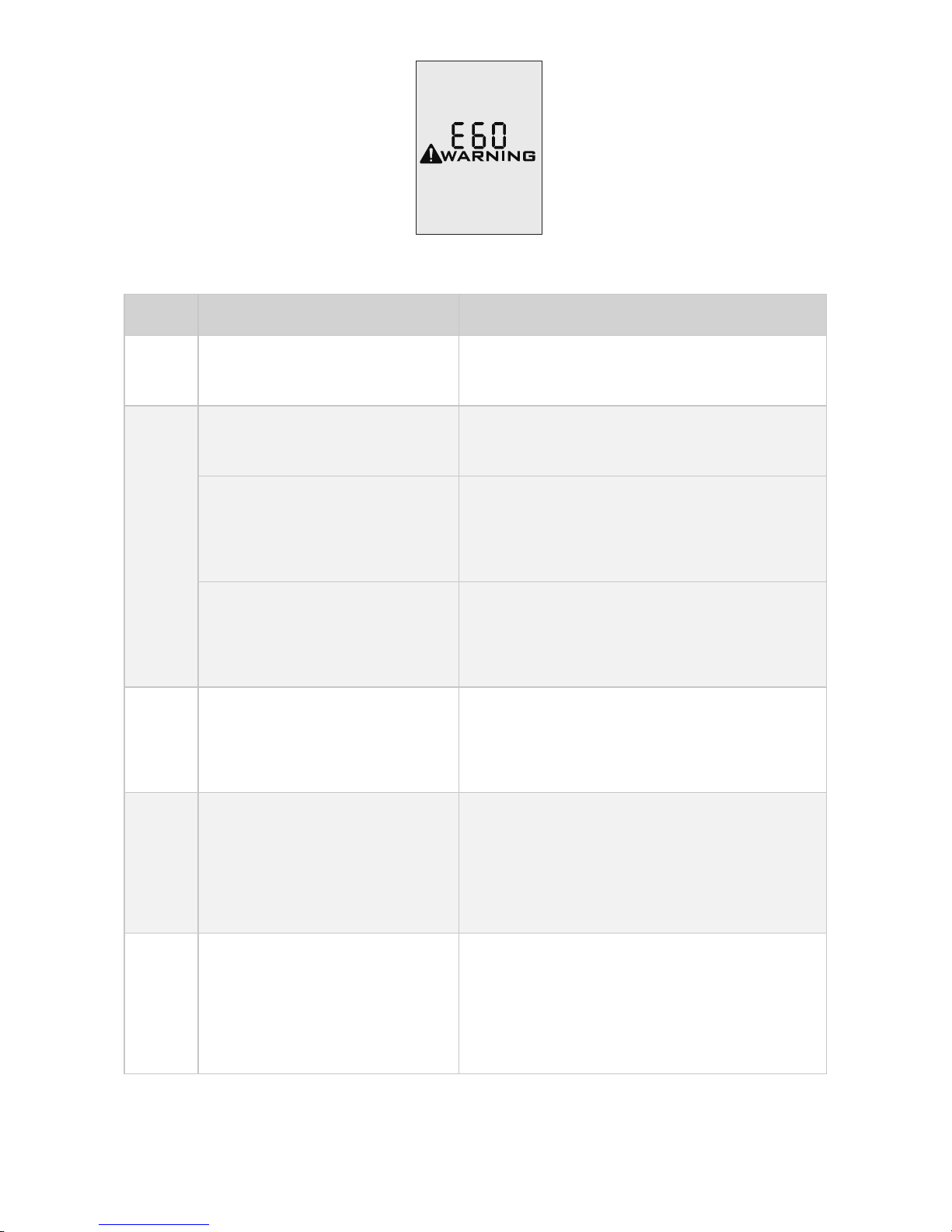
5.6 Warning Messages
When the outboard motor is running in abnormal conditions or out of order,
a warning message with an error code will display on the LCD screen.
Figure 5-17 is an example. Please nd more error codes and corresponding
solutions in the below table.
Main
Switch
48V
+-
Main
Switch
48V
+-
Page 37
35
Figure 5-17
Codes Causes Solutions
E01
Battery voltage is over the
operating range.
Replace a battery based on
suggested operation specications.
E02
Propeller may be blocked,
causing motor overcurrent
Please refer to the solution to E10.
Motor fails or circuit
board fails causing motor
overcurrent
Try to turn off the main switch and
wait for 10 seconds then turn on the
switch again.
Loosen power cable
connector leads to
overcurrent
Check if the power cable connector
is loosen.
E06
The battery voltage level
is too low.
Operate the outboard at low power.
Please charge the battery as soon
as possible.
E07
Motor idling error - the
propeller not immersed in
water or detached from
the motor shaft.
Mount the outboard properly and
check if the propeller has been
attached tightly.
E10
Motor stall, which may
be caused by blocked
propeller
Turn off power, then clean up the
things winding around the propeller.
Test if the propeller can be rotated
by hand before operation.
Page 38

36
Code Cause Solution
E11
The temperature of
motor is too high.
Stop operating the outboard and wait
until the temperature falls within the
normal operating temperature range.
E12
The temperature of
circuit board is too high.
Stop operating the outboard and wait
until the temperature falls within the
normal operating temperature range.
E14
Failure was found in
the motor temperature
sensors.
Try to turn off the main switch and wait
for 10 seconds then turn on the switch
again.
E15
Failure was found
in the circuit board
temperature sensors.
Try to turn off the main switch and wait
for 10 seconds then turn on the switch
again.
E16
Calibration Abnormality
of Current Sensor
Please contact the dealer for help.
E22
MCU Communication
Abnormality
Please restart to see if the error
disappears, if not, please contact your
dear for help.
E25
The remote is not
paired to the outboard
Pair the remote to the outboard.
E30
Throttle position
sensor failure, should
recalibrate the throttle
position sensor.
Please refer to section 5.3.3
Recalibration to recalibrate the throttle
position sensor.
E40 System running failure
Please restart the Remote Control/
Tiller and the outboard.
E55
NAVY Battery is
running out of power
Charge NAVY Battery
E56
Communication
Error between NAVY
outboard and NAVY
battery
Check if the communication cable
between NAVY outboard and NAVY
battery is well connected, if yes, please
restart the system.
Page 39
37
Code Cause Solution
E57
NAVY battery
overcurrent
1. Ensure the paralleled NAVY batteries
have similar voltage with pressure
difference within 2V.
2. Ensure the power cable and battery
are rmly connected to avoid poor
contact.
3. Restart the battery when the error
occurs and keep the parallel state for 30
minutes to wait for the batteries to selfbalance the voltage.
4. If the error occurs, users can also
continue operating after restarting the
battery, but do not operate at full power
state. The operating power is suggested
to be lower than two thirds of full power.
Please fully charge the battery after use.
E60
The Remote
Control/Tiller is
running out of
power.
Please connect the Remote Control/Tiller
to the outboard by a communication
cable. Please refer to section 5.2.2
Charged by Wired Connection
All
charac ter s
display
The motor has no
power.
Connect the battery to the outboard and
then turn on the main switch.
Device addresses
mismatch.
Please refer to section 5.4 Pairing
Remote Control/Tiller with the Outboard
Motor and pair the Remote Control/Tiller
with the outboard motor again.
Buzzer
beeps
Normal
The buzzer beeps when the remaining
battery drops to 50%, 20% and 10%.
If the problem persists, please consult your ePropulsion authorized
dealer for assistance.
Page 40
38
6 Congurations
6.1 Preference Settings
It’s advised to set display preference by these steps before operation.
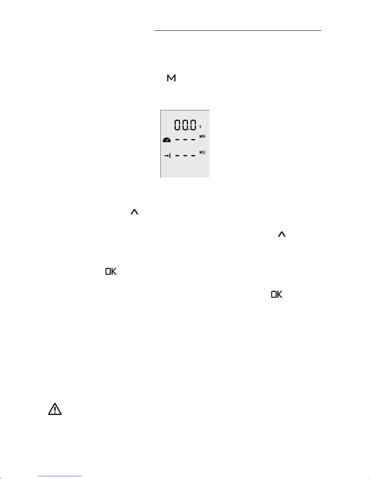
Step1: In power-on state, press “ ” button and hold to enter the preference
setting page as shown in Figure 6-1. Users can choose display items based
on personal needs and preference.
Figure 6 -1
Step2: On the preference setting page, the blinking item is the object waiting
to be set. Press the “
” button to view options for the blinking item. For
example, in Figure 6-1, if “ V ” is blinking on the preference setting page, it
means that “ V ” has other alternate options. Just press the “
” button,
and “ V ” will switch to “ % ”, i.e. the displayed item is switched from voltage
to battery level.
Step3: Press “ ” button to save setting for the current item and skip to
the next item simultaneously.
Step4: When all the items have been set well, long press the “ ” button to
save all the settings and return to the main page.
6.2 Battery Conguration
Accurate battery configuration helps achieve precise estimation of the
battery's discharging state. When using an ePropulsion NAVY Battery
(standard), battery conguration is self-activated by the control system given
that all the communication cables are well connected. When not using NAVY
Batteries, users should manually congure the batteries via Remote Control/
Tiller at the rst time use, otherwise the batteries may not work properly.
Battery configuration should be carried out if a battery with different
type/capacity/voltage is connected to NAVY 3.0 for the rst time.
Page 41
39
Battery Conguration Process LCD Displaying
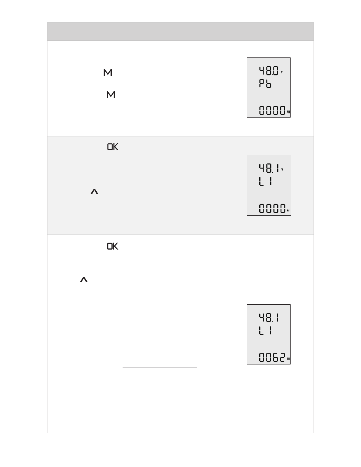
Step1: First, turn on the main switch and the
Remote Control/Tiller.
Then, press “ ” button and hold to enter the
preference setting page.
Next, press “ ” button and hold again to
enter the battery setting page. Users can see
the voltage value blinking and it’s ready for
conguration.
Step2: Press “ ” button and skip to the next
item: battery type.
Choose the battery type according to the
battery you use.
Pressing “
” button to switch the battery type
options between Pb, Li and LFE.
Pb: Lead-acid battery Li: Lithium battery
LFE: Lithium-ion ferrous phosphate battery
Step3: Press “ ” button to save battery type
and skip to the below battery capacity setting
item.
Press “
” button to change the value and set
the battery capacity according to the battery
you use.
Note that the unit of capacity is “Ah”, usually the
capacity of battery is expressed in “Wh”, and
we can get the capacity in “Ah” by following the
below formula:
Capacity in Wh
Capacity in Ah =
Nominal voltage in V
Eg. if users use a 3000Wh Lithium battery
with 48.1V nominal voltage, then the battery
is about 62.37Ah, so you can set 62Ah as the
capacity setting.
Page 42
40
Battery Conguration Process LCD Displaying
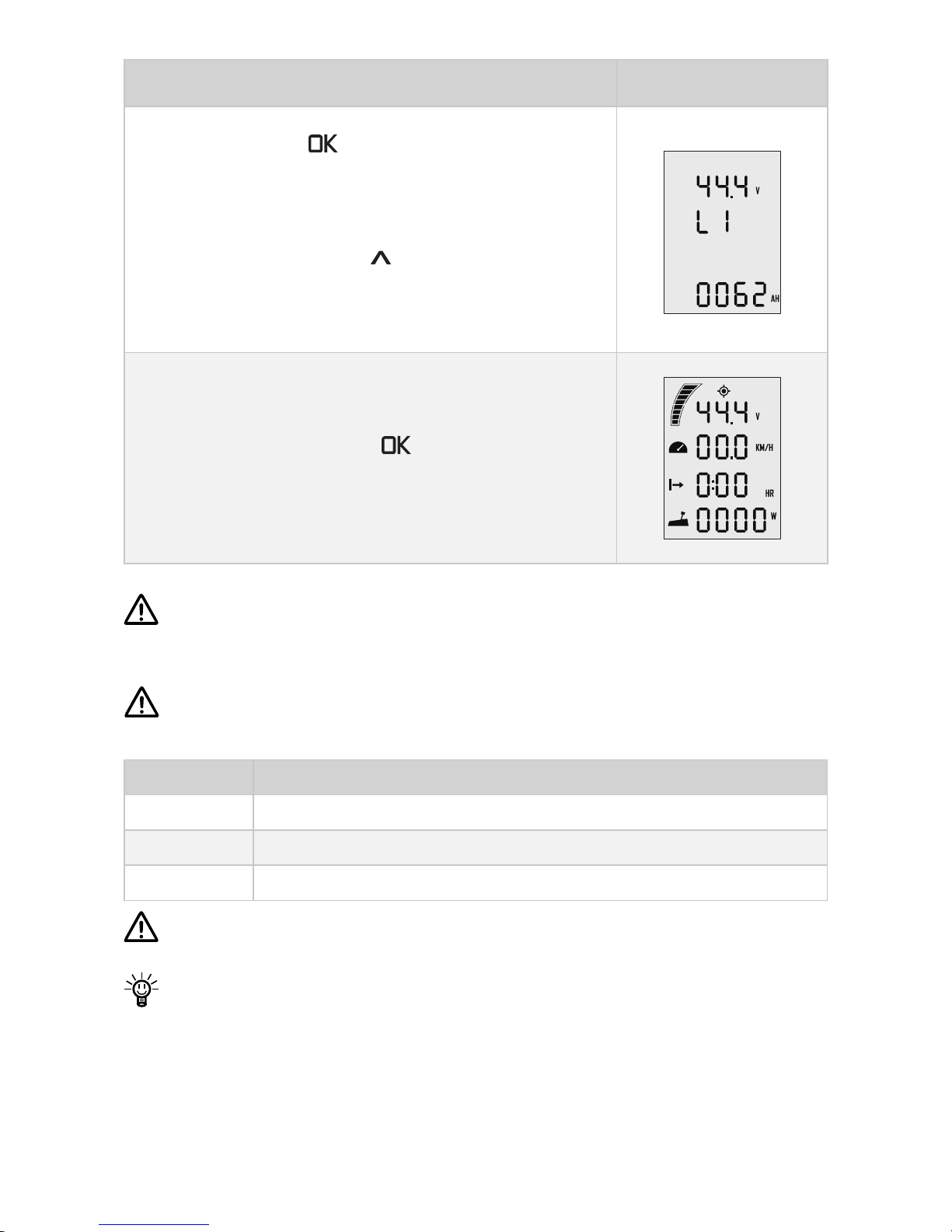
Step4: Press “ ” button to save battery
capacity setting, and it will return to the top
battery nominal voltage setting item.
The voltage options are varied according to the
battery types. Press “
” button to view the
options and select the closest nominal voltage
value according to the battery you use.
Step5: Press and hold “ ” button to save all
the settings and return to the main page.
Lithium batteries, lead acid batteries and lithium iron phosphate batteries
are recommended to use with NAVY 3.0. Other types of battery may fail
to make NAVY 3.0 work properly.
When you use the below batteries, please set battery type and rated
voltage value based on the parameters in the following table.
Battery type Nominal Voltage options
LI 43.2V 44.4V 45.6V 46.8V 48.1V 49.4V 50.4V 51.8V 53.2V
Pb 44.0V 46.0V 48.0V 50.0V 52.0V 54.0V
LFE 44.8V 48.0V 51.2V
Update the battery configuration is necessary if a different type of
battery has been applied.
When using non-ePropulsion batteries, before starting the outboard,
users should configure the batteries via the Remote Control/Tiller for
the rst time use, otherwise the batteries may not work properly.
Page 43
41
7 Checklist before Use
1. Ensure the propeller is correctly and rmly mounted on the outboard.
2. Ensure the outboard is correctly and rmly mounted on the boat.
3. Ensure the throttle and steering wheel are installed in proper position bef ore turning on the power.
4. Ensure the throttle travels smoothly with no obstacles.
5. Before connecting the battery, check and make sure there is no poor con-
tacts or defects in cables.
6. Check and ensure the main switch is able to power on and off normally.
After that, turn off the main switch.
7. Ensure the battery has enough power.
8. Ensure the Remote Control/Tiller has enough power.
Start the outboard only when the propeller is beneath water, as the
rotating propeller is dangerous.
If the cable is immersed in water, please dry it completely before
connecting it to the battery or power on the system.
Page 44

42
8 Starting the Outboard
1. Complete the check list.
2. Remove the kill switch from the Remote Control/Tiller.
3. Push/Turn the throttle to zero position.
4. Connect the battery to the outboard.
5. Fix the outboard with a proper trim angle.
6. Turn on the main switch. If the outboard is connected to a NAVY battery,
please also press the battery power button to power on.
7. Press “ ” button to turn on the Remote Control/Tiller and
the main page will display.
8. Carry out preference setting and battery conguration if necessary.
9. Tie the kill switch to your wrist or life vest, then attach the kill switch on
the Remote Control/Tiller.
10. Push/Turn the throttle slowly to start your outboard.
Page 45
43
9 Stopping the Outboard
Usually, it’s recommended to stop the outboard as the following procedures.
1. Return the throttle to zero position.
2. Wait until the outboard stops, then detach the kill switch from the Remote
Controller/Tiller.
3. Press and hold the “ ”button until the Remote Control/Tiller is
powered off.
4. Turn off the main switch. If the outboard is connected to a NAVY battery,
please also press the battery power button to power off.
5. Tilt the outboard above water surface or detach it from boat.
If the outboard motor will not be used soon, it’s recommended to keep
the outboard out of water, otherwise erosion may occur. In addition, it is
recommended to apply protective coating.
The outboard will stop if one of the situations occurs.
1) The throttle is in zero position.
2) The kill switch is not in the correct position of Remote Control.
3) The main switch is off.
4) The communication between Remote Control/Tiller and
outboard breaks.
5) The connection between battery and outboard breaks.
6) Failure exists in the control system (e.g. motor is blocked or the low
battery voltage level is detected).
Page 46
44
10 Trim Angle Adjusting
Only adjust the outboard trim angle when the outboard is stationary.
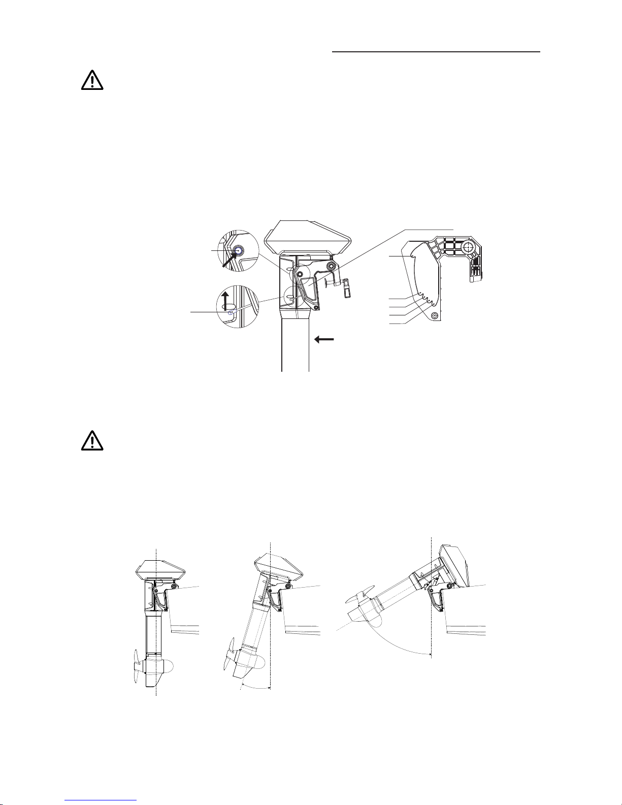
There are ve trim angle options including 60°,15°,10°,5° and 0°. Adjust the
outboard trim angle based on specic conditions. E.g. when the boat is in
shallow water or the outboard is not in use, tilt the outboard and adjust the
trim angle to 60°. For normal operation, x it to a proper trim angle where the
shaft is vertically downward during operation. Be reminded that the best trim
angle varies by boat type, operation conditions, weather, etc.
60°
15°
10°
5°
0°
Release Button
Back Side
Trim Lever
Figure 10-1
Tilting up
Detach the Tiller rst before tilting the outboard motor up to the position
with max trim angle.
Pull up the trim lever with one hand, and lift the outboard shaft with the other
hand to enlarge the trim angle to a particular degree. Then, release the trim
lever to lock the trim angle.
0°
15°
60°
Figure 10-2
Page 47
45
Tilting Down
The release button is raised when the trim angle is maximum at 60° position.
Press the release button and tilt up the propeller shaft slightly to about 80°
position, then lay it down, and the outboard shaft will return to 0° position.
It’s suggested to test with different trim angles to find the optimal
trim angle for the boat and operation. Note that the speed should be
increased gradually during the test, and check if there are any abnormal
situations. Stop the outboard and decrease the trim angle if necessary.
Slight and gentle operations are recommended when tilting up and
down.
The trim lever is only used to increase the trim angle from 0° to 60°. If
users want to decrease the trim angle, eg. from 15° to 5°, follow these
steps: first, tilt the outboard shaft to the maximum angle (60°); then,
press the release button to return the outboard shaft to the 0° position;
last, use the trim lever to tilt up the shaft to the 5° position.
Page 48
46
11 Maintenance
11.1 Notes
Regular maintenance helps to keep your outboard in optimal operation state.
Do not start the outboard in shallow water. Adjust the trim angle to 60° to
avoid running aground. Only use the outboard in water deep enough.
Washing the outboard with fresh water after sailing in salt water in order to
avoid erosion.
Disconnect the battery with the outboard before maintenance.
Conduct the maintenance work according to the instructions from
ePropulsion authorized dealers.
Only use ePropulsion original parts for replacement and maintenance.
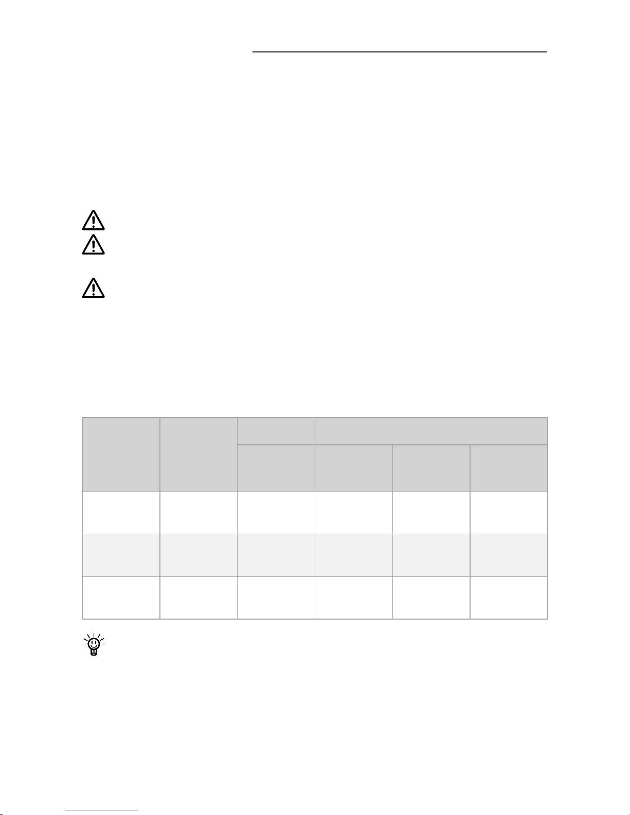
11.2 Maintenance Time Table
Regular maintenance helps to keep the outboard in its optimal operating
state. The following table shows a general maintenance schedule, the time
could be adjusted according to specic needs.
Item Operations
Initial Every
10 hours
(1 month)
50 hours
(3 months)
100hours
(6 months)
200 hours
(12 months)
Anode
Check/
Replace
□ □
Greasing
Points
Grease
□
Propeller
and Pin
Check/
Replace
■ ■
The“□”symbol indicates checks may carry out by users. The“■”symbol
indicates work should be carried out by your dealer.
Page 49

47
11.3 Propeller Maintenance
Disconnect the battery with outboard before maintenance.
Gloves are recommended to protect your hand from sharp propeller
edges.
Check the propeller according to the following instructions, then refer to
then refer to section 2.2 Mounting the Propeller to replace a new propeller if
necessary.
1. Check the propeller blades for wear, cavitation erosion and other damage.
2. Check the pin for wear and damage.
3. Check for water plants, shing net or line twine around the propeller.
4. Replace a new anode if necessary.
Page 50
48
12 Transportation and Storage
12.1 Transport
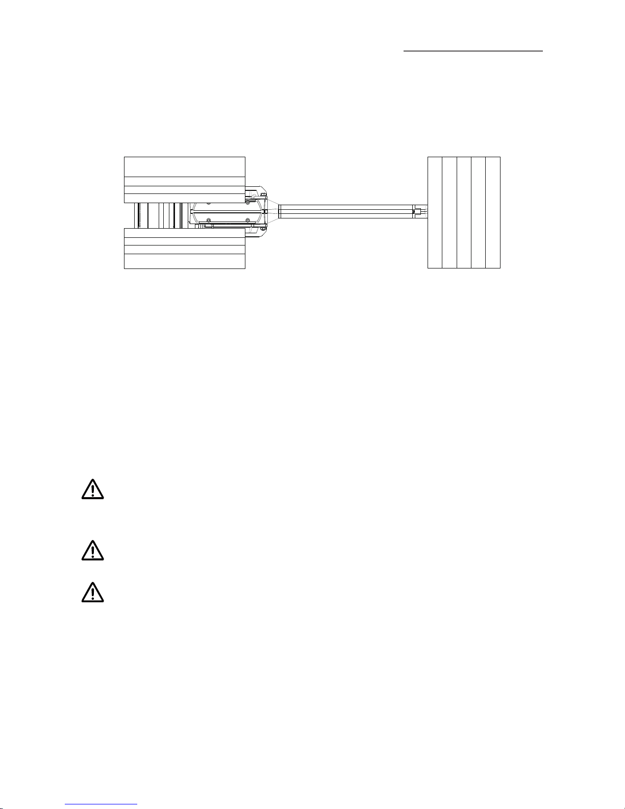
For long distance transport, please use the ePropulsion original packing
materials to pack the outboard before delivery.
Figure 12-1
12.2 Placement
When placing the outboard on a surface, ensure the surface is flat and
horizontal. It’s better to put some damping cushion underneath.
12.3 Storage
If you are not using the outboard motor for more than 2 months, it’s advised
to contact your dealer to clean and check the outboard prior to storage.
It’s recommended to pack the outboard with ePropulsion original packing
materials for storage.
Get adequate damping protection measures before transport and
storage. And ensure the propeller receives no pressure if the propeller
is mounted on the propeller shaft.
Store the outboard in a well-ventilated and dry area without direct
sunshine.
Ensure the storage temperature is proper (-25°C~50°C / -13°F~122°F)
to avoid the coolant freezing.
Page 51

49
13 Emergency Situations
13.1 Collision
If the outboard strikes some object beneath the water, please follow below
procedures.
1. Stop the outboard immediately and then turn off the main switch.
2. Check the mechanical structure to see if there are damages.
3. Return to the nearest harbor or pier in low power.
4. Call your dealer to check the outboard.
13.2 Sodden Outboard
If the outboard is sodden, stop it immediately and turn off the main switch
then disconnect the battery. Bring the outboard to the dealer. And ensure the
outboard is thoroughly inspected before operating it again.
13.3 Low Battery Level
When the battery voltage is lower than 42V, the throttle power will be limited
gradually along with the voltage drop. When the battery voltage drops below
39V, the outboard will stop automatically to prevent battery over-discharge.
If this happens when the outboard is far away from the shore, and there
is an alternative battery, it’s recommended to wait until the battery voltage
recovered to 42V or above. You can restart the outboard with throttle power
below 1000W.
13.4 Over-temperature Protection
The maximum input power of NAVY 3.0 has been limited to be below 3KW
when the system temperature is a little high. If the system temperature
continues to be warm and surpasses a threshold, the outboard motor will
shut down automatically to avoid over-temperature. Users should stop
operating the outboard and wait until the temperature falls within the normal
operating temperature range.
Page 52
50
14 Warranty
The ePropulsion limited warranty is provided for the rst end purchaser of an
ePropulsion product. Consumers are entitled to a free repair or replacement
of defective parts or parts which do not conform with the sales contract.
This warranty operates in addition to your statutory rights under your local
consumer law.
14.1 Warranty Policies
ePropulsion Innovation (HK) Ltd. warrants its products to be free of defects
in material and workmanship for a limited period since the date of purchase.
Once a fault is discovered, the user has the right to make a warranty claim
under the ePropulsion warranty policy.
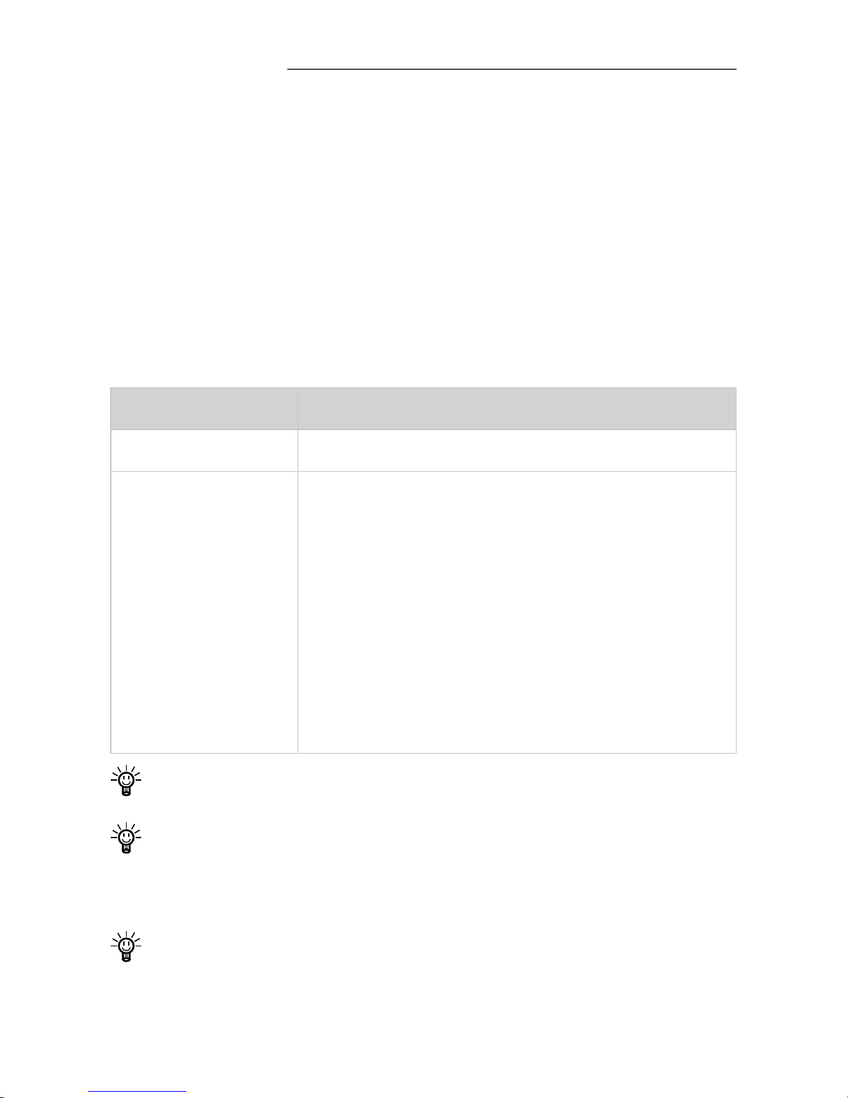
Product Warranty Expiration Date
NAVY 3.0 Two years after the date of purchase.
Repaired/Replaced
Parts
Three months since the date of maintenance.
Notes:
1. If the three-month period overlaps with the
original warranty period, the warranty against
these replaced or repaired parts still expires two
years after the date of purchase.
2. If the three-month period exceeds the original
warranty period, the warranty of the repaired or
replaced parts expires by end of the third month
since date of maintenance.
In order to validate the warranty, users are required to ll in the Warranty
Card in the package in advance.
Keep the product label in an intact state and record the serial number on
the label. Never tear the label off the product. An ePropulsion product
without the original product label will not be applicable to warranty
services provided by ePropulsion.
The warranty is valid only when the information is correct and complete.
Page 53

51
Free warranty is only validated upon the presentation of legal serial
number, Warranty Card, and evidence of purchase from an authorized
ePropulsion dealer.
Valid date of purchase should be established by the rst-hand purchaser
with original sales slip.
Free warranty is not transferable and will not be reissued.
14.2 Out of Warranty
Make sure the product is properly packed during delivery, the original
ePropulsion package is recommended. If the product got further damaged
due to improper packing during delivery, the furtherly damaged part will be
deemed as out of warranty coverage.
In addition, faults or damages caused by the following reasons are also
excluded from warranty scope within the covered period:
Any improper operation contradicts the user manual.
Accident, misuse, wishful abuse, physical damage overcharging or
unauthorized repair.
Dropping, improper care or storage.
You should be noted that minor faults like normal wear and tear that
pose no inuence on the intended function of the product are also not
covered by the warranty.
Consumables are out of warranty scope.
14.3 Warranty Claim Procedures
If you find your product defective, you can make a claim to your dealer
following below procedures:
1. Fill in Warranty Card correctly and completely in advance. Then make
your warranty claim by sending it to your authorized ePropulsion service
partner together with valid proof of purchase. Usually these documents
are required when making a warranty claim: the Warranty Card, ex-factory
serial number, and evidence of purchase.
2. Send the defective product to your authorized ePropulsion service point
after getting the confirmation. Note that the label should be kept intact.
You can also deliver the product to your authorized ePropulsion dealer
Page 54

52
after getting conrmation.
3. The defective components or parts will be either repaired or replaced
according to the diagnosis made by the ePropulsion authorized service
partner.
4. If your warranty claim is accepted, the equipment will be repaired or
replaced free of charge. Note that any delivery cost incurred in the
process is at your charge.
5. After careful examination and confirmation by ePropulsion authorized
dealer, the defective or faulty components will be repaired or replaced
with brand new ones against the actual condition.
6. In case your warranty claim be rejected, an estimated repair charge with
round trip delivery cost will be sent for confirmation. ePropulsion
authorized service point will conduct maintenance accordingly only after
your conrmation.
If warranty expires, you can still enjoy maintenance services from
authorized ePropulsion service partners with minimum maintenance
charge.
Page 55

Page 56

Thanks for reading this user manual.
If you have any concerns or nd any problems while reading,
please don't hesitate to contact us. We are delighted to offer
service for you.
ePropulsion Innovation (HK) Ltd.
Website: www.epropulsion.com
Email: [email protected]
 Loading...