

Page 1

User’User’
User’
User’User’
ManualManual
Manual
ManualManual
An An
AMD SocAMD Soc
An
AMD Soc
An An
AMD SocAMD Soc
mainboard (100/133MHz)mainboard (100/133MHz)
mainboard (100/133MHz)
mainboard (100/133MHz)mainboard (100/133MHz)
kk
k
kk
et et
et
et et
ss
s
ss
A PrA Pr
ocessor basedocessor based
A Pr
ocessor based
A PrA Pr
ocessor basedocessor based
60000028K+100
SupporSuppor
Suppor
SupporSuppor
TRADEMARK
All products and company names are trademarks or registered
trademarks of their respective holders.
These specifications are subject to change without notice.
ts PC1600/PC2100 Memorts PC1600/PC2100 Memor
ts PC1600/PC2100 Memor
ts PC1600/PC2100 Memorts PC1600/PC2100 Memor
Manual Revision 1.0
January 11, 2002
y Modulesy Modules
y Modules
y Modulesy Modules
Page 2

Page 3

Section 1 Introduction
Components Checklist ........................................1-1
Overview
AMD DuronTM & AthlonTM Processors .............1-2
Accelerated Graphics Port..................................1-3
Ultra ATA66/100/133 .........................................1-3
Hardware Monitoring ..........................................1-3
Mainboard Form-Factor ......................................1-4
I/O Shield Connector .......................................... 1-5
Power-On/Off (Remote)..................................... 1-5
System Block Diagram........................................ 1-6
Section 2 Features
Mainboard Features ............................................. 2-1
Section 3 Installation
Mainboard Detailed Layout................................. 3-2
T able of Contents
Page
Easy Installation Procedure
CPU Insertion ......................................................3-3
Jumper Settings ...................................................3-5
System Memory Configuration ..........................3-6
Device Connectors ..............................................3-8
STR (Suspend T o RAM) Function....................... 3-12
Section 4 Award BIOS Setup
BIOS Instructions.................................................4-1
Standard CMOS Setup ......................................... 4 -2
Advanced BIOS Features.....................................4-3
Advanced Chipset Features ................................. 4-7
Page 4

Integrated Peripherals .........................................4-12
Power Management Setup................................... 4-17
PNP/PCI Configuration Setup ............................4-21
PC Health Status .................................................. 4-23
Frequency/Voltage Control ................................. 4-25
Defaults Menu ..................................................... 4-26
Supervisor/User Password Setting .....................4-27
Exit Selecting ...................................................... 4-28
Section 5 Driver Installation
Easy Driver Installation ....................................... 5-1
Appendix
Appendix A
GHOST 5.1/6.03 Quick User’s Guide (Optional) ... A-1
Appendix B
Update Your System BIOS .................................. B-1
Appendix C
EEPROM BIOS Remover ................................... C- 1
Appendix D
Avance® Media Player User’s Guide .................. D-1
Page 5
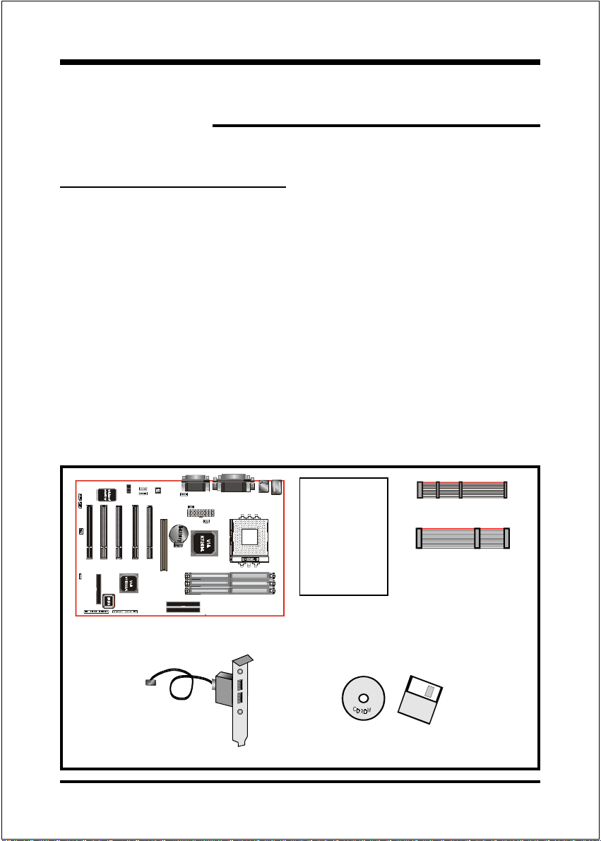
Components Checklist
99
9 A. (1) Mainboard
99
99
9 B. (1) User’s manual
99
99
9 C. (1) Floppy ribbon cable
99
99
9 D. (1) ATA-66/100 Hard drive ribbon cable
99
E. (1) USB Cable (Optional)
99
9 F. ( 1 ) Driver and utility
99
Introduction
Section 1
INTRODUCTION
USER’S
MANUAL
C
E
B
A
or
E
F
Page 1-1
Page 6

Introduction
Overview
AMD DuronTM & AthlonTM Processors
The AMD AthlonTM is a seventh-generation micro architecture with an integrated
L2 cache, which is powerful enough to support the bandwidth requirements of a
large range of applications, hardware, graphics, and memory technologies. These
processors implement advanced design techniques such as:
Socket A (PGA 462)
200/266MHz system interface based on the Alpha™ EV6 bus protocol.
Three out-of-order, superscalar, pipelined Multimedia Units.
Three out-of-order, superscaler, pipelined Integer Units.
Fixed-sized internal instruction formats (MacroOPs).
72-entry Instruction Control Units.
AMD enhanced 3DNow!™ technology
L1 and L2 caches.
Dynamic branch prediction.
Socket A is the name for AMD’s new socketed interface designed to support both
AMD DuronTM and AMD AthlonTM processors. This innovation is made possible
by integrating the L2 cache memory on chip with the processor. Socket A will
help enable smaller enclosures, and ultimately result in a wider variety of solutions in the market.
The AMD DuronTM & AthlonTM processors in the Socket A format continue to
deliver the ultimate performance for cutting-edge applications. Both bring to
desktop systems running industry-standard x86 software superscalar RISC
performance. Being provided in the Socket A format they are the world’s most
powerful x86 processors. They easily deliver the highest integer, floating-point,
and 3D multimedia performance for applications running on x86 platforms
around.
Page 1-2
Page 7

Introduction
The AMD DuronTM processor is derived from the AMD AthlonTM processor core.
It features full-speed, on-chip cache memory, a 200MHz front side system bus,
and enhanced 3DNow!™ technology. Although both processors are related, there
are key differences. The AMD AthlonTM processor is targeted at the performance
segment, and as such will have more cache memory and higher clock speeds.
Accelerated Graphics Port
(AGP or A.G.P.)
Typically, 3D graphics rendering requires a tremendous amount of memory, and
demands ever increasing throughput speed as well. As 3D products for the
personal computer become more and more popular, these demands will only
increase. This will cause a rise in costs for both end users and manufacturers.
Lowering these costs as well as improving performance is the primary motivation
behind AGP. By providing a massive increase in the bandwidth available between
the video card and the processor, it will assist in relieving some of these pressures
for quite sometime.
Ultra ATA/66/100/133
The board provides Ultra ATA/66/100/133 Bus Master IDE controller, that
support Ultra ATA/66/100/133 protocols, perfect for such demanding applications
as real-time video, multimedia, and high performance operating system. A new
IDE cable is required for Ultra ATA/66/100/133. This cable is an 80 conductor
cable; however the connectors are, of course, backwards compatible with ATA/33.
Hardware Monitoring
Hardware monitoring allows you to monitor various aspects of your systems
operations and status. The features include CPU temperature, voltage and RPM of
fan.
Page 1-3
Page 8
Introduction
Mainboard Form-Factor
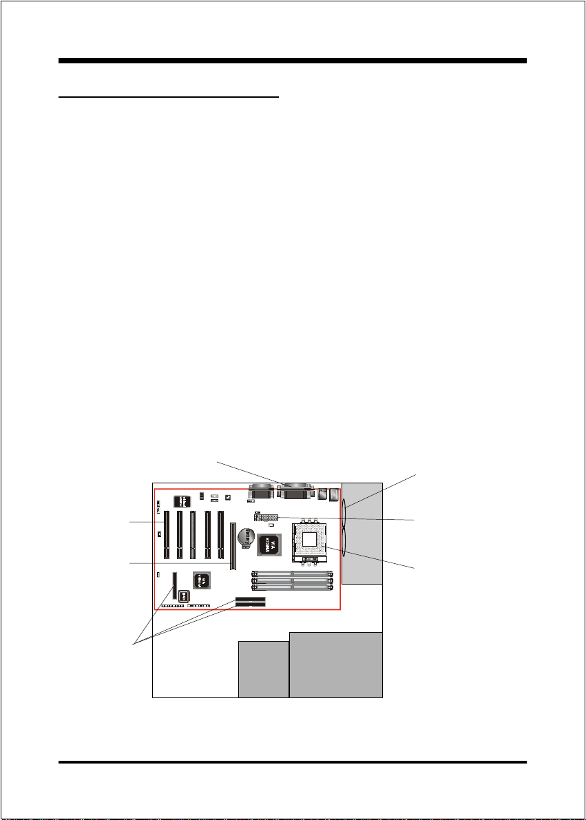
The board is designed with ATX form factor - the new industry standard of chassis.
ATX form factor is essentially a Baby-AT baseboard rotated 90 degrees within the
chassis enclosure and a new mounting configuration for the power supply. With
these changes the processor is relocated away from the expansion slots, allowing
them all to hold full length add-in cards. ATX defines a double height aperture to
the rear of the chassis which can be used to host a wide range of onboard I/O.
Only the size and position of this aperture is defined, allowing PC manufacturers
to add new I/O features (e.g.; TV input, TV output, joystick, modem, LAN, etc.) to
systems. This will help systems integrators differentiate their products in the
marketplace, and better meet your needs.
• Smaller size promotes a smaller system size.
• I/O shield does not need to be retooled in an ATX 2.01 or later. The
mainboard should be used in an ATX 2.01 (or later) compliant case.
• A smaller power supply can be used. High integration on mainboard
reduces the system cost.
PCI slots
AGP slot
Floppy / IDE
connectors
Page 1-4
Expandable I/O
3 1/2"
Bay
Figure 2: Summary of ATX chassis features
5 1/4"
Bay
ATX
Power
Supply
Single chassis
fan for system
ATX power connector
CPU
Page 9
Introduction
I/O Shield Connector
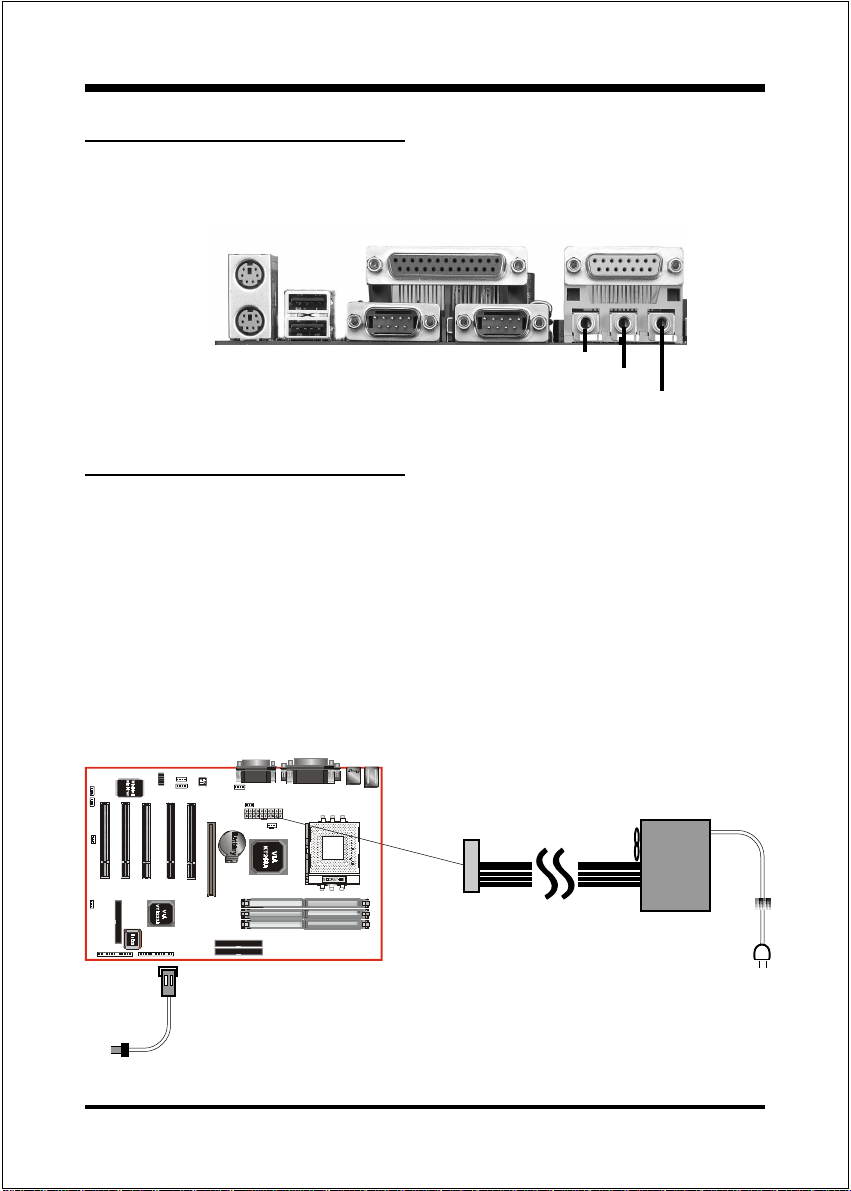
The board is equipped with an I/O back panel. Please use the appropriate I/O
shield (figure 3).
parallel port
Joystick/Midi port
PS/2 Mouse
PS/2
KEYBOARD
USB port
COM1
Figure 3: I/O back panel layout
COM2
Speaker
Line_in
MIC
Power-On/Off (Remote)
The board has a single 20-pin connector for ATX power supplies. For ATX power
supplies that support the Remote On/Off feature, this should be connected to the
systems front panel for system Power On/Off button. The systems power On/Off
button should be a momentary button that is normally open.
The board has been designed with “Soft Off" functions. You can turn Off the
system from one of two sources: The first is the front panel Power On/Off
button, and the other is the "Soft Off" function (coming from the M/B’s onboard
circuit controller) that can be controlled by the operating system such
asWindows® 95/98/SE/ME or Windows®2000.
ATX
POWER SUPPLY
J 3
Case (chassis) Power
ON/OFF button (J 3)
Figure 4: Simple ATX Power ON/OFF Controller
Page 1-5
Page 10
Introduction
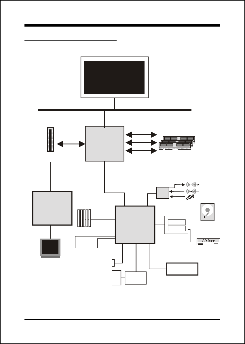
System Block Diagram
Socket A
Processor
AMD
133/100MHz
4X
AGP Slot
Graphic
Video
66MHz
AGP Bus
and memory
PCI Slots
USB 0,1 USB 2,3
PS/2 Mouse
PS/2 Keyboard
Serial Port 1
Serial Port 2
LPT Port
FDD
PAC
PCI Bridge
controller
KT266A
V_Link
MA [0:13]
MD [0:63]
MDS [0:7]
VT8233A
I/O Bridge
LPC
W83697HF
DDR SDRAM
266/200MHz
AC
97
Flash Memory
IDE 1
IDE 2
BIOS
HDD
(AT A-66/100/133)
Page 1-6
Figure 5: System Block Diagram
Page 11

Section 2
FEATURES
Mainboard Features:
PROCESSOR
- The Socket A compatible AMD AthlonTM XP processor 1500+ to 1800+,
and 600MHz to 1.4GHz AMD AthlonTM and AMD DuronTM Processors
CHIPSET
- VIA KT266A AGPset (KT266A + VT8233A)
DRAM MODULE
- 184pin DDR DIMM x 3 for PC1600/2100 Memory
- DRAM Size: 64MB to 1.5GB
Features
EXP ANSION SLOT
- PCI x 5, 4X AGP x 1
ONBOARD I/O
Winbond 83697HF LPC I/O integrated with
- FDD, Parallel and Serial, Fast IR, Game Port
ONBOARD PCI / IDE
- PCI Bus IDE Port with PIO / Ultra DMA-100/133 x 2 (Up to 4 Devices)
I/O CONNECTOR
- PS/2 Mouse and PS/2 style Keyboard
- COM1, COM2, Printer, Audio-in/out, MIC & Game Port connectors
USB
- USB connector x 4 (2 for Opt.)
Page 2-1
Page 12

Features
BIOS
- A ward Plug & Play BIOS
Built-in AC97 Digital Audio
- Dual full-duplex Direct Sound channels
- FM synthesis for legacy compatibility
- Supports game and MIDI port
EXTENDED FUNCTION
- Supports Hardware Monitoring Function by W83697HF
- Supports exclusive KBPO (KeyBoard Power On) Function via BIOS
- Supports Wake-On-LAN Function
- Supports STR (Suspend To RAM) power saving Function
- Supports CPU Clock and CPU Ratio settings via BIOS
- Supports CPU Vcore , Memory and AGP Voltage setting via BIOS
FORM FACT OR
- 305mm x 200mm ATX Size
Page 2-2
Page 13
Installation
Section 3
INST ALLATION
Page 3-1
Page 14
Installation
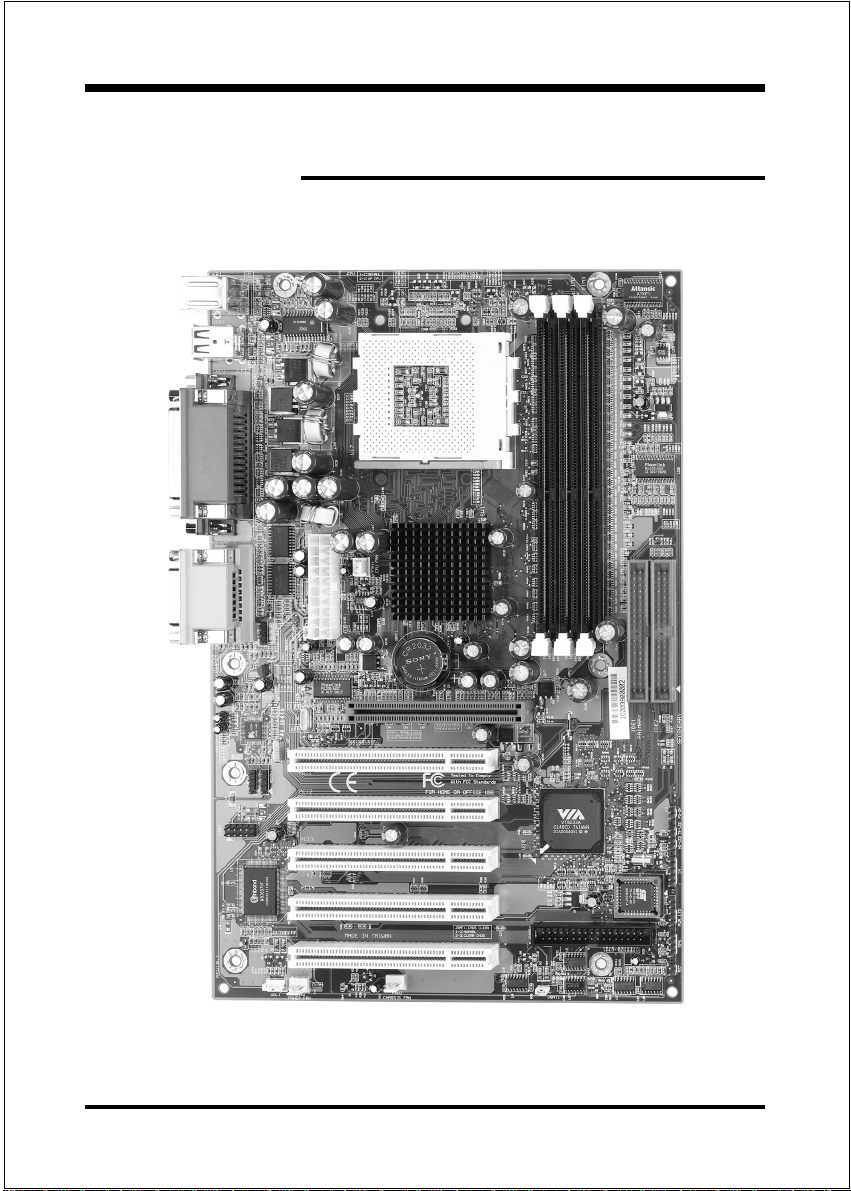
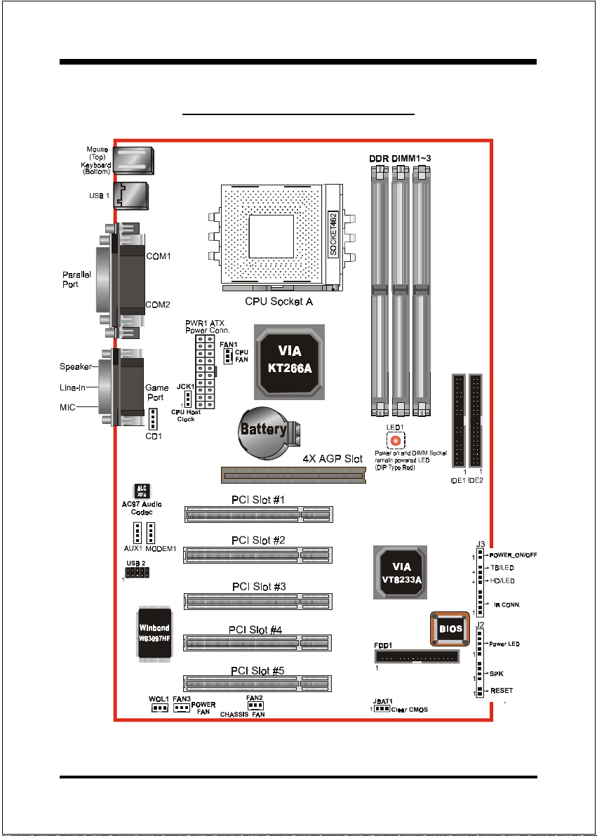
Mainboard Detailed Layout
Page 3-2
Figure 1
Page 15
Installation
Easy Installation Procedure
The following must be completed before powering on your new system:
3-1. CPU Insertion
3-2. Jumper Settings
3-3. System memory Configuration
3-4. Device Connectors
3-5. STR Function
Section 3-1
CPU Insertion
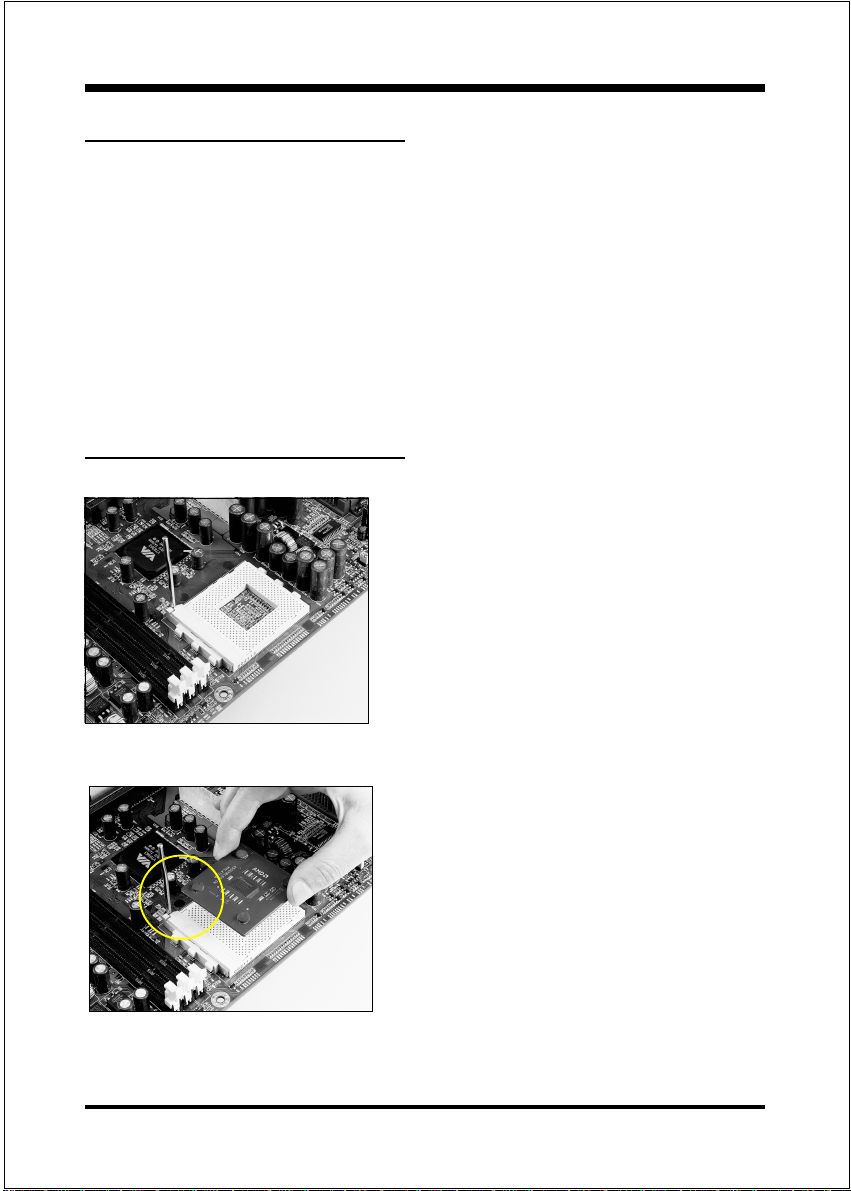
CPU Insertion: (use AMD AthlonTM as reference)
Step 1
Open the socket by raising the actuation
lever.
Figure 2
Figure 3
Step 2
Insert the processor.
Ensure proper pin 1 orientation by aligning
the FC-PGA corner marking with the socket
corner closest to the actuation arm tip. The
pin field is keyed to prevent mis-oriented
insertion.
Don’t force processor into socket. If it does
not go in easily, check for mis-orientation and
debris.
Make sure the processor is fully inserted
into the socket on all sides.
Page 3-3
Page 16
Installation
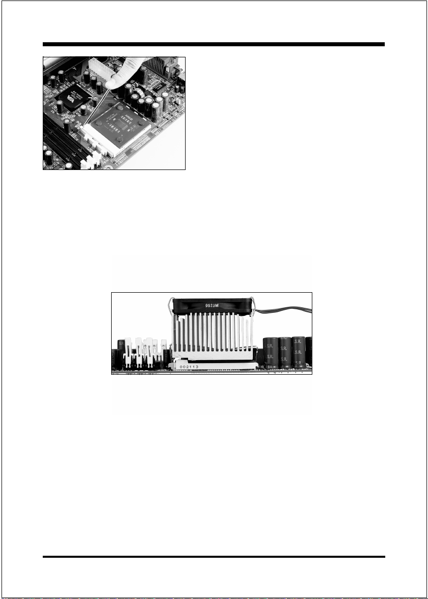
Step 3
Close the socket by lowering and
locking the actuation lever.
Figure 4
Step 4
Thermal compound and qualified heatsink recommended by AMD are a must to
avoid CPU overheat damage. For more information about installing your CPU,
please refer to the AMD website article “Socket A AMD processor and Heatsink
Installation Guide” http://www.amd.com/products/cpg/athlon/pdf/23986.pdf.
Page 3-4
Figure 5
Page 17
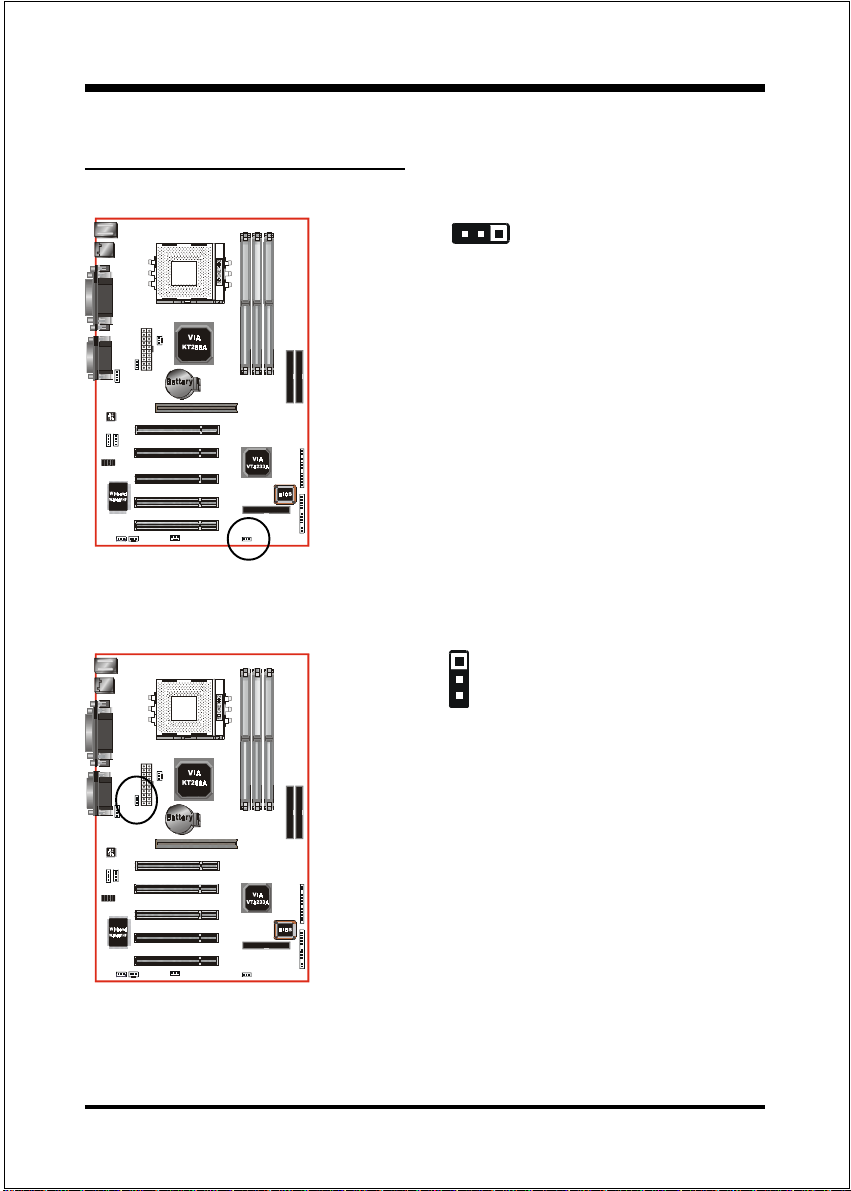
Section 3-2
Jumper Settings
Installation
JBAT1
1
CMOS Clear
= 1-2 Normal (Default)
= 2-3 Clear CMOS
JCK1
1
CPU Host Clock Select
= 1-2 100MHz (Default)
= 2-3 133MHz
Page 3-5
Page 18
Installation
Section 3-3
System Memor y Configur ation
Memory Layout
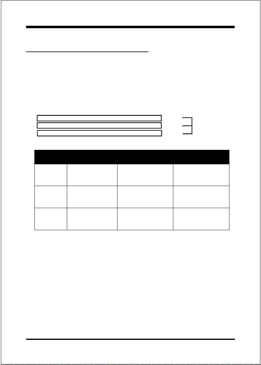
The board supports (3) PC1600/2100 184-pin DIMMs (Dual In-line Memory
Module). The DIMMs is for DDR SDRAM (Double-Data-Rate Synchronous
DRAM) only.
Figure 6 and Table 1 show several possible memory configurations.
DDR DIMM 1
DDR DIMM 2
DDR DIMM 3
Bank 0/1
Bank 2/3
Bank 4/5
DDR
Synchronous
DRAM
Figure 6
yromeMlatoT
BM215=
mumixaM
BG1=
mumixaM
BG5.1=
mumixaM
1MMIDRDD
)1/0knaB(
*MARDSRDD
,BM652,BM821,BM46
1XBM215
*MARDSRDD
1XBM215
*MARDSRDD
1XBM215
enoNenoN
,BM652,BM821,BM46
1XBM215
,BM652,BM821,BM46
1XBM215
2MMIDRDD
)3/2knaB(
*MARDSRDD
,BM652,BM821,BM46
*MARDSRDD
,BM652,BM821,BM46
enoN
1XBM215
3MMIDRDD
)5/4knaB(
*MARDSRDD
,BM652,BM821,BM46
Table 1
* DDR SDRAM supports 64, 128, 256, 512MB DIMM modules.
* We recommend using PC1600 Memory Module only for front-side bus
100MHz.
* DO NOT MIX the unbuffered and registered DDR SDRAM on DIMM1 ,
DIMM2 and DIMM3 socket.
* This mainboard doesn’t support ECC memory module.
* Supports PC1600 modules with 2-2-2 timing.
* Supports PC2100 modules with 2-2-2 timing.
Page 3-6
Page 19
Installation
DIMM Module Installation
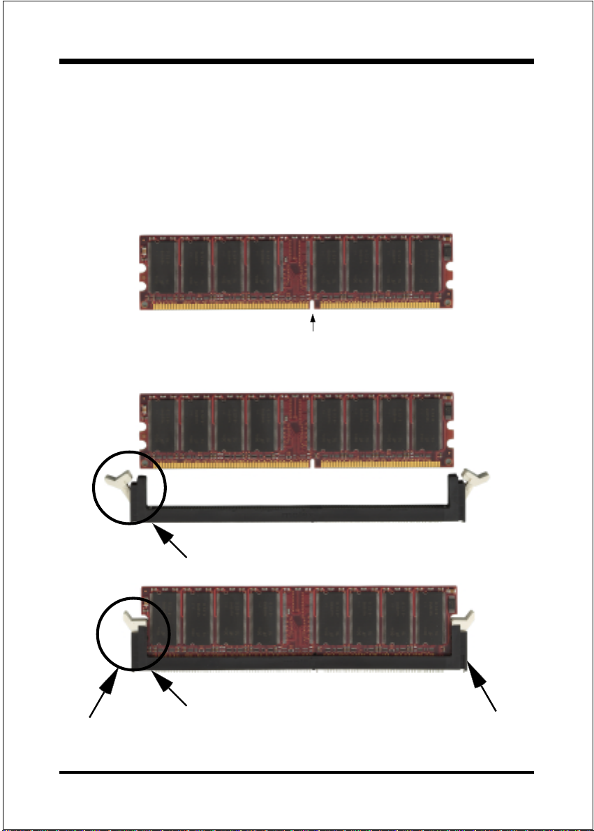
Figure 7 displays the notch marks and what they should look like on your DDR
DIMM memory module.
DIMMs have 184-pins and one notch that will match with the onboard DDR
DIMM socket. DIMM modules are installed by placing the chip firmly into the
socket at a 90 degree angle and pressing straight down (figure 8) until it fits tightly
into the DIMM socket (figure 9).
CENTER KEY ZONE
(2.5 V DRAM)
Figure 7
Figure 8
DIMM Module clip before installation
Figure 9
DIMM Module clip after installation
T o remove the DIMM module simply press down both of the white clips on either
side and the module will be released from the socket.
Page 3-7
Page 20
Installation
Section 3-4
Device Connectors
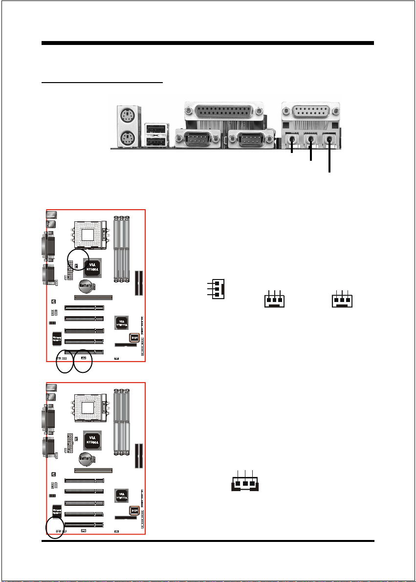
PS/2 Mouse
PS/2
KEYBOARD
FAN1
FAN2
FAN3
USB port
parallel port
COM1
COM2
Joystick/Midi port
Speaker
Line_in
Figure 10
MIC
FAN1 / FAN2 / FAN3:
• The plug-in for CPU/Chassis/Power Fan power
FAN1:
CPU Fan
Rotation
+12V
GND
F AN2:
Chassis Fan
GND
+12V
Rotation
FAN3:
Power Fan
GND
+12V
NC
Page 3-8
WOL1: WOL (Wake On LAN) Connector
Reserved for NIC (Network Interface
Card) to wake the system.
+5V Standby
GND
PME
Page 21
Installation
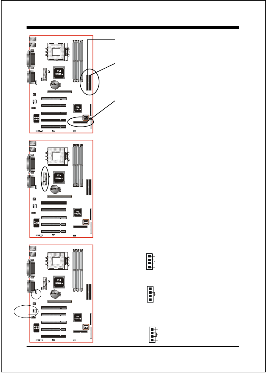
IDE1:Ultra DMA-66/100/133 Primary IDE
Connector (Blue color)
IDE2:Ultra DMA-66/100/133 Secondary IDE
Connector (Blue color)
FDD1: Floppy Controller Connector (Black
color)
PW1: ATX Power Connector
• 20-pin power connector
AUX1
MODEM1
CD1
CD1: CD Audio_IN Connector
CD_IN_Right
CD_Reference
CD_IN_Left
1
AUX1: Auxiliary Line_IN Connector
AUX_IN_Right
GND
AUX_IN_Left
1
MODEM1: Telephony Connector for Modem
audio output
Modem_IN
GND
Modem_OUT
1
Page 3-9
Page 22
Installation
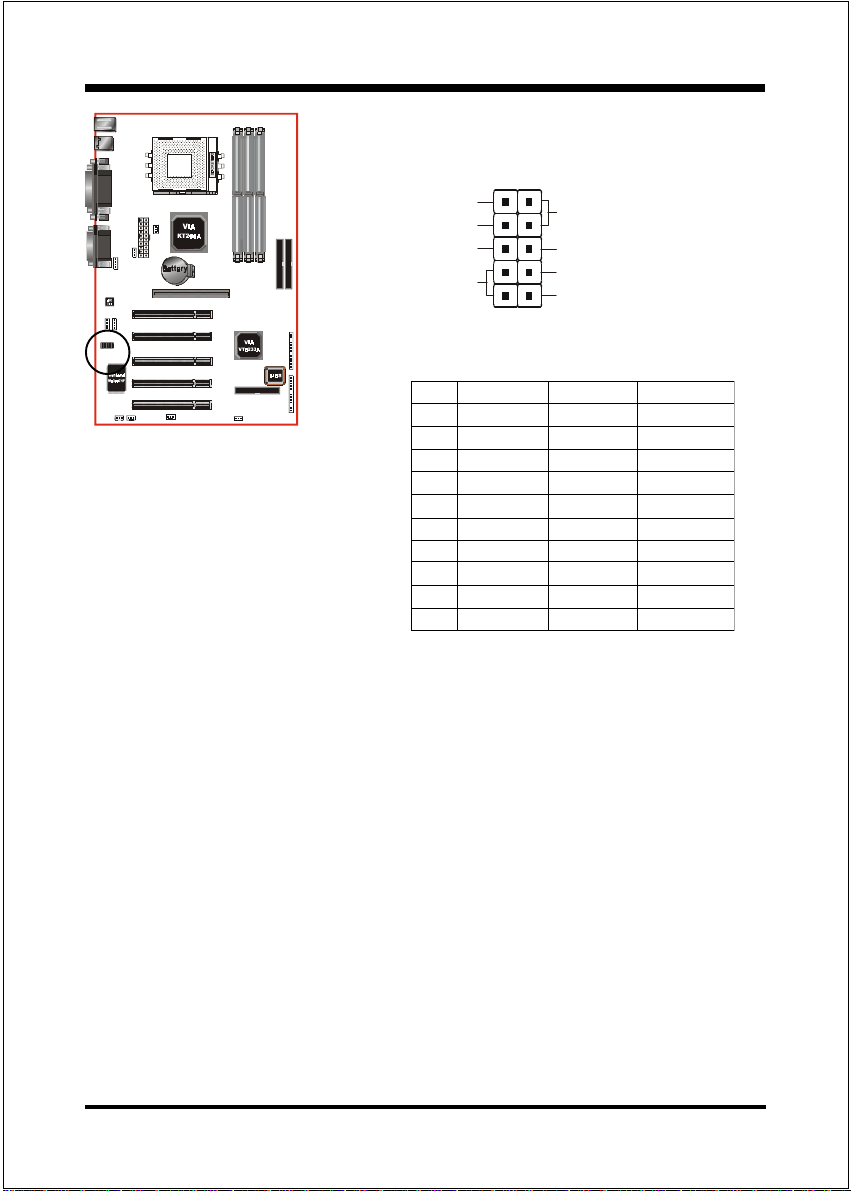
USB2: USB port header pins for share with
four USB ports.
VCC
-Data
+Data
GND
1
5
6
GND
+Data
-Data
VCC
10
USB2
USB port header pin descriptions.
#NIProloceriWemaNlangiStnemmoC
1deRccVrewoPelbaC
2etihWataD-ataD
3neerGataD+ataD
4kcalBdnuorGdnuorGelbaC
5kcalBdnuorGdnuorGesaC
6kcalBdnuorGdnuorGesaC
7kcalBdnuorGdnuorGelbaC
8neerGataD+ataD
9etihWataD-ataD
01deRccVrewoPelbaC
Page 3-10
Page 23
Installation
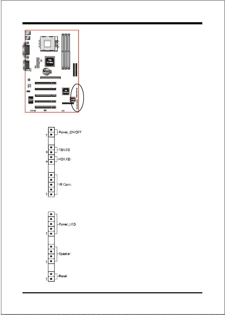
Power On/Off
(This is connected to the power button on the
case. Using the Soft-Off by Pwr-BTTN
feature, you can choose either Instant Off
(turns system off immediately), or 4 sec delay
(you need to push the button down for 4
seconds before the system turns off). When
the system is in 4 sec delay mode, suspend
mode is enabled by pushing the button
momentarily.)
Turbo LED indicator
LED ON when higher speed is selected
J3
J2
IDE LED indicator
LED ON when Onboard PCI IDE Hard disks is
activate
IR Connector
1. VCC 4. GND
2. NC 5. IRTX
3. IRRX
Power LED
Power LED connector
1. Power LED(+) 4. NC
2. N/C 5. GND
3. GND
Speaker
Connect to the system's speaker for beeping
1. Speaker 3. GND
2. N/C 4. GND
Reset
Closed to restart system.
Page 3-11
Page 24

Installation
3-5 STR (Suspend To RAM) Function
The board supports the STR power management state by maintaining the
appropriate states on the DDR SDRAM interface signals. The power source
must be kept alive to the DDR SDRAM during STR (ACPI S3). Advanced
Configuration Power Interface (ACPI) provides more Energy Saving Features
for operating systems that supporting Instant ON and QuickStartTM function.
1. To enable the ACPI function and use the STR functionally to save your system
energy, you are recommended to confirm the following requirements:
a. Please do install all ACPI qualified add-on cards such as AGP, LAN,
Modem cards.
b. In BIOS, please select “ ACPI function: Enable” and “ACPI Suspend Type:
S3(STR)” in the Power Management Setup menu.
c. Then, please install the Windows® 98SE/ME or Windows® 2000.
d. Restart your system.
e. Getting in to the “Advanced” of the Power Management icon of Control
Panel, and selecting the “Stand By” in the Power Buttons.
2. Getting start with STR function, please click the START button and choose
Shut Down. Then, select the Stand By option in the Shut Down Windows box
to get into STR mode.
Here are the differences between STR power saving mode and Green (or
Suspend) mode:
a. It is the most advanced Power Management mode
b. It cuts all the power supplied to peripherals except to Memory - max.
power saving
c. It saves and keeps all on-screen data including any executed applications to
DDR SDRAM.
Page 3-12
Page 25

Installation
d. You must push the Power button connected with onboard J3 pin to wake up
your system (not to click to mouse or press keyboard to wake up the
system).
Just pushing Power button, your system will quickly back to the last screen for
you.
The “LED Indicator for ACPI Status” table shown below will guide you and give
you a reference for ACPI status on this mainboard.
Onboard’s
LED
Location
LED1
(Red LED)
J2
PW_LED
ACPI Onboard’s LED Status Indicator Table
Status
Plug in the ATX
Power Core
Power ON
J3(PW-ON)
Green Mode
(S1)
STR
(S3)
Shutdown
(Soft-OFF)
(S5)
OFF ON ON ON OFF
OFF ON Blinking Blinking OFF
Page 3-13
Page 26

Installation
Page Left Blank
Page 3-14
Page 27
BIOS
Section 4
AWARD BIOS SETUP
Main Menu
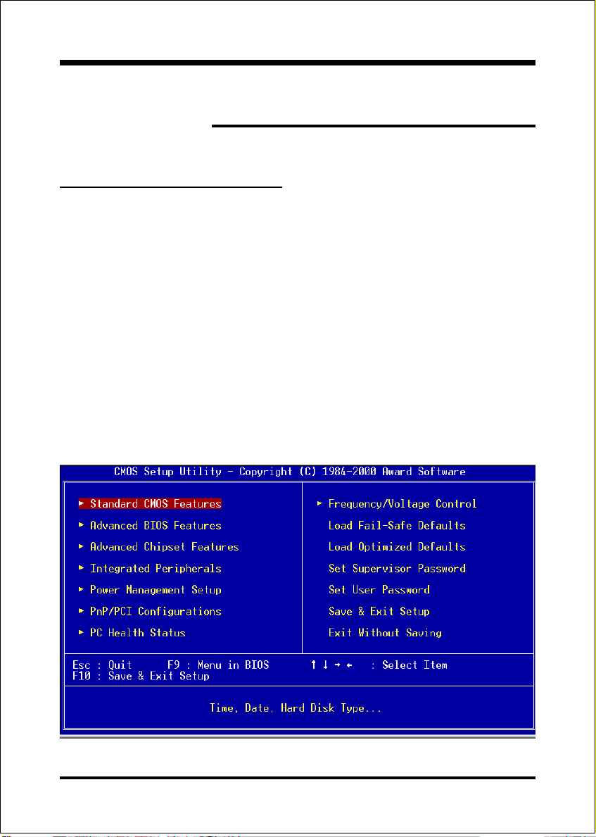
Award’s ROM BIOS provides a built-in Setup program which allows user to
modify the basic system configuration and hardware parameters. The modified
data will be stored in a battery-backed CMOS, so that data will be retained even
when the power is turned off. In general, the information saved in the CMOS
RAM will stay unchanged unless there is a configuration change in the system,
such as hard drive replacement or a device is added.
It is possible for the CMOS battery to fail, this will cause data loss in the CMOS
only. If this does happen you will need to reconfigure your BIOS settings.
To enter the Setup Program :
Power on the computer and press the <Del> key immediately, this will bring you
into the BIOS CMOS SETUP UTILITY.
Figure 1: CMOS Setup Utility
Page 4-1
Page 28

BIOS
The menu displays all the major selection items. Select the item you need to
reconfigure. The selection is made by moving the cursor (press any direction key
) to the item and pressing the ‘Enter’ key. An on-line help message is displayed at
the bottom of the screen as the cursor is moved to various items which provides a
better understanding of each function. When a selection is made, the menu of the
selected item will appear so that the user can modify associated configuration
parameters.
4-1 Standard CMOS Setup
Choose “Standard CMOS Setup” in the CMOS SETUP UTILITY Menu (Figure 2).
The Standard CMOS Setup allows the user to configure system settings such as
the current date and time, type of hard disk drive installed, floppy drive type, and
display type. Memory size is auto-detected by the BIOS and displayed for your
reference. When a field is highlighted (use direction keys to move the cursor and
the <Enter> key to select), the entries in the field can be changed by pressing the
<PgDn> or the <PgUp> key.
Page 4-2
Figure 2: Standard CMOS Setup
Page 29
BIOS
NOTE: If the hard disk Primary Master/Slave and Secondary Master/
Slave are set to Auto, then the hard disk size and model will be
auto-detected.
NOTE: The “Halt On:” field is used to determine when to halt the system
by the BIOS if an error occurs.
NOTE: Floppy 3 Mode support is a mode used to support a special 3.5”
drive used in Japan. This is a 3.5” disk that stores only 1.2 MB,
the default setting for this is disabled.
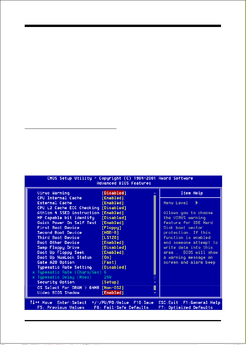
4-2 Advanced BIOS Features
Selecting the “BIOS FEATURES SETUP” option in the CMOS SETUP UTILITY
menu allows users to change system related parameters in the displayed menu.
This menu shows all of the manufacturer’s default values for the board.
Pressing the [F1] key will display a help message for the selected item.
Figure 3: BIOS Features Setup
Page 4-3
Page 30

BIOS
Virus Warning: During and after the system boots up, any attempt to write to the
boot sector or partition table of the hard disk drive will halt the system and an
error message will appear.
You should then run an anti-virus program to locate the virus. Keep in mind that
this feature protects only the boot sector, not the entire hard drive.
The default value is Disabled.
Enabled: Activates automatically when the system boots up causing a warning
message to appear when anything attempts to access the boot sector.
Disabled: No warning message will appear when anything attempts to access the
boot sector.
Note: Many disk diagnostic programs that access the boot sector table can
trigger the virus warning message. If you plan to run such a program,
we recommend that you first disable the virus warning.
CPU Internal Cache: This controls the status of the processor’s internal cache
area. The default is Enabled.
Enabled: This activates the processor ’s internal cache thereby increasing
performance.
Disabled: This deactivates the processor’s internal cache thereby lowering
performance.
External (L2) Cache: This controls the status of the external (L2) cache area.
The default is Enabled.
Enabled: This activates the CPU’s L2 cache thereby increasing performance.
Disabled: This deactivates the CPU’s L2 cache thereby lowering performance.
CPU L2 Cache ECC Checking: This control if the CPU’s L2 Cache will support
Error Checking and Correcting (ECC). The default is Disabled.
Enabled : Enables ECC support for the CPU’s L2 cache. Performance will decrease
2% ~ 4%.
Disabled: Disables ECC support for the CPU’s L2 cache.
Athlon 4 SSED instruction: This item allows you to disable Athlon 4 new SSED
instruction. The default is Enabled.
The choice: Enabled, Disabled.
Page 4-4
Page 31

BIOS
MP Capable bit identify: This item allows you to identify Athlon MP
Processor, if this function is Enabled. The default is Disabled.
The choice: Enabled, Disabled.
Quick Power On Self Test: This category speeds up the Power On Self Test
(POST). The default is Enabled.
Enabled: This setting will shorten or skip of the items checked during POST.
Disabled: Normal POST.
First /Second/Third/Other Boot Device: The BIOS attempts to load the operat-
ing system from the devices in the sequence selected in these items.
The choice: Floppy, LS120, HDD-0, SCSI, CDROM, HDD-1, HDD-2, HDD-3,
ZIP100, USB-FDD, USB-ZIP, USB-CDROM, USB-HDD, LAN, Disabled.
Swap Floppy Drive: This will swap your physical drive letters A & B if you are
using two floppy disks. The default is Disabled.
Enabled: Floppy A & B will be swapped under the O/S.
Disabled: Floppy A & B will be not swapped.
Boot Up Floppy Seek: During Power-On-Self-Test (POST), BIOS will deter-
mine if the floppy disk drive installed is 40 or 80 tracks. Only 360K type is 40
tracks while 760K, 1.2MB and 1.44MB are all 80 tracks. The default is Enabled.
Enabled: The BIOS will search the floppy disk drive to determine if it is 40 or
80 tracks.
Disabled: The BIOS will not search for the type of floppy disk drive by track
number.
Note: BIOS can not tell the difference between 720K, 1.2MB and 1.44MB
drive types as they are all 80 tracks.
Boot Up NumLock Status: This controls the state of the NumLock key when the
system boots. The default is On.
On: The keypad acts as a 10-key pad.
Off: The keypad acts like the cursor keys.
Gate A20 Option: This refers to the way the system addresses memory above
1MB (extended memory). The default is Normal.
Page 4-5
Page 32

BIOS
Normal: The A20 signal is controlled by the keyboard controller or chipset
hardware.
Fast: The A20 signal is controlled by Port 92 or chipset specific method.
Typematic Rate Setting: This determines the keystrokes repeat rate.
The default is Disabled.
Enabled: Allows typematic rate and typematic delay programming.
Disabled: The typematic rate and typematic delay will be controlled by the
keyboard controller in your system.
Typematic Rate (Chars/Sec): This is the number of characters that will be
repeated by a keyboard press. The default is 6.
The Choice: 6, 8, 10, 12, 15, 20, 24, 30 characters per second.
Typematic Delay (msec): This setting controls the time between the first and
the second character displayed by typematic auto-repeat. The default is 250.
The Choice: 250, 500, 750, 1000 msec.
Security Option: This category allows you to limit access to the System and Setup,
or just to Setup. The default is Setup.
System: The system will not boot and the access to Setup will be denied if the
correct password is not entered at the prompt.
Setup: The system will boot; but the access to Setup will be denied if the
incorrect password is not entered at the prompt.
OS Select For DRAM > 64MB: Some operating systems require special
handling. Use this option only if your system has greater than 64MB of memory.
The default is Non-OS2.
OS2: Select this if you are running the OS/2 operating system with greater
than 64MB of RAM.
Non-OS2: Select this for all other operating systems and configurations.
Video BIOS Shadow: This option allows video BIOS to be copied into RAM. V ideo
Shadowing will increase the video performance of your system. The default is Enabled.
Enabled: Video shadow is enabled.
Disabled: Video shadow is disabled.
Page 4-6
Page 33
BIOS
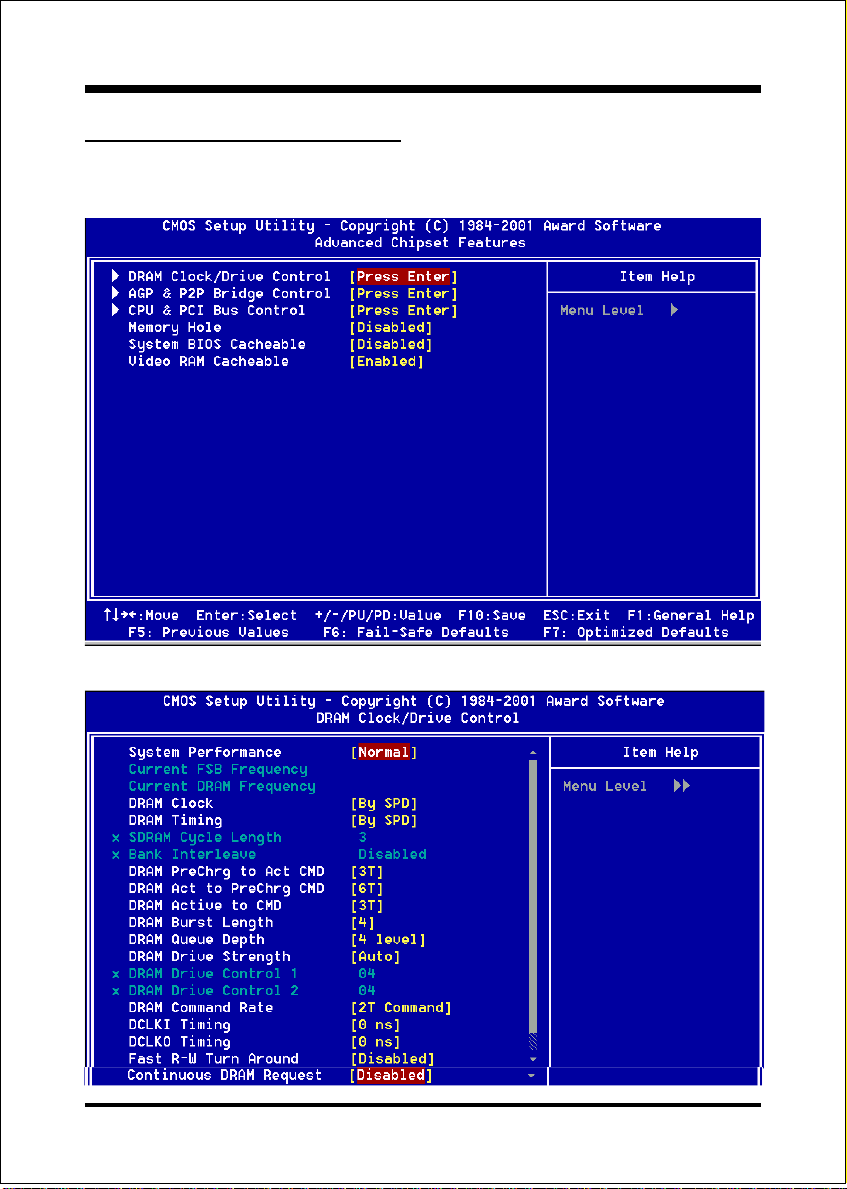
4-3 Advanced Chipset Fea tures
Choose the “CHIPSET FEATURES SETUP” in the CMOS SETUP UTILITY menu
to display following menu.
Figure 4: Chipset Features Setup
100MHz
133MHz
Page 4-7
Page 34

BIOS
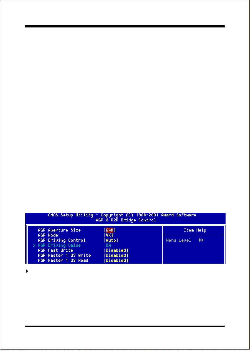
DRAM Clock/Drive Control
System Performance : This item will help you to configure your system
performance quickly and easily. There are four selections. When a selection is
made, the other related items will automatically vary values.
The Choice: Normal, Fast, Fastest, Turbo.
Note: If you select the higher performance, compatibility problem could be
occurred.
Current FSB Frequency: CPU clock frequency information. (No option/
Display only).
Current DRAM Frequency: DRAM frequency information. (No option/
Display only).
DRAM Clock : The item will synchronize/asynchronize DRAM clock
operation.
100MHz: DRAM is running at 100MHz frequency.
133MHz: DRAM is running at 133MHz frequency.
By SPD: SDRAM clock by SPD data.
DRAM Timing : Select SPD for setting SDRAM timing by SPD.
The Choice: Manual, SPD.
SDRAM Cycle length: This setting defines the CAS timing parameter of the
SDRAM in terms of clocks. Default is by SPD.
The Choice: 2, 2.5, 3.
Bank Interleave: The item allows you to set how many banks of SDRAM
support in your mainboard. Default is by SPD.
The Choice: 2 Bank, 4 Bank, Disabled.
DRAM PreChrg to Act CMD: Setup the minimum row precharge time.
The Choice: 2T, 3T.
DRAM Act to PreChrg CMD: Setup the minimum RAS pulse width.
The Choice: 5T, 6T.
Page 4-8
Page 35
BIOS
DRAM Active to CMD: Setup the minimum CAS to RAS delay.
The Choice: 2T, 3T.
DRAM Burst Length:
The Choice: 4, 8.
DRAM Queue Depth:
The Choice: 4 level, 2 level, 3 level.
DRAM Drive Strength: Setup the DRAM’s driving current strength.
The Choice: Auto, Manual.
DRAM Command Rate: Setup the timing at each cycle.
The Choice: 1T Command, 2T Command.
DCLKI/O Timing:
The Choice: 0ns, 0.5ns, 1ns, Auto.
Fast R-W Turn Around: This item controls the DRAM timing. It allows you
to enable/disable the fast/write turn around.
The Choice: Enabled, Disabled.
Continuous DRAM Request:
The Choice: Enabled, Disabled.
AGP & P2P Bridge Control
AGP Aperture Size: The amount of system memory that the AGP card is
allowed to share with. The default is 64MB.
The Choice: 4, 8, 16, 32, 64, 128, 256MB.
AGP Mode: Chipset AGP Mode support.
The choice: 1X, 2X, 4X.
Page 4-9
Page 36

BIOS
AGP Driving Control: This item allows you to adjust the AGP driving force.
Choose Manual to key in a AGP Driving Value in the next selection. This field
is recommended to set in Auto for avoiding any error in your system.
AGP Fast Write: Selecting Enabled allows to use Fast Write Protocol for 4X
AGP card.
AGP Master 1 WS Write: When Enabled, Writes to the AGP (Accelerated
Graphics Port) are executed with one wait states.
The Choice: Enabled, Disabled.
AGP Master 1 WS Read: When Enabled, Reads to the AGP (Accelerated
Graphics Port) are executed with one wait states.
The Choice: Enabled, Disabled.
CPU & PCI Bus Control
PCI1/2 Master 0 WS Write: When Enabled, Writes to the PCI bus are
commanded with zero wait states.
The Choice: Enabled, Disabled.
PCI Delay Transaction: The chipset has an embedded 32-bit posted write buffer
to support delay transactions cycles. Select Enabled to support compliance with
PCI specification version 2.1.
The Choice: Enabled, Disabled.
Page 4-10
Page 37

BIOS
Memory Hole : You can reserve this memory area for the use of ISA adaptor
ROMs. The default is Disabled.
Enabled: This field enables the main memory (15~16MB) to remap to ISA BUS.
Disabled: Normal Setting.
Note: If this feature is enabled you will not be able to cache this memory
segment.
System BIOS Cacheable: This allows you to copy your BIOS code from slow
ROM to fast RAM. The default is Disabled.
Enabled: The option will improve system performance. However, if any program
writes to this memory area, a system error may result.
Disabled: System BIOS non-cacheable.
Video RAM Cacheable: This option allows the CPU to cache read/writes of the
video RAM. The default is Enabled.
Enabled: This option allows for faster video access.
Disabled: Reduced video performance.
Page 4-11
Page 38
BIOS
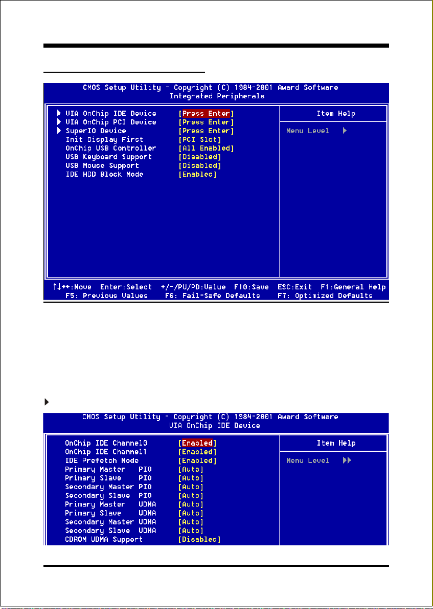
4-4 Integrated Peripherals
Figure 5: Integrated Peripherals
Note: If you do not use the Onboard IDE connector, then you will need to set Onboard
Primary PCI IDE: Disabled and Onboard Secondary PCI IDE: Disabled
Note: The Onboard PCI IDE cable should be equal to or less than 18 inches (45
cm.).
VIA OnChip IDE Device
Page 4-12
Page 39

BIOS
OnChip IDE Channel0/1: The default value is Enabled.
The integrated peripheral controller contains an IDE interface with support for two
IDE channels. Select Enabled to activate each channel separately.
The choice: Enabled, Disabled.
IDE Prefetch Mode: Enable prefetching for IDE drive interfaces that support
its faster drive accesses. If you are getting disk drive errors, change the setting
to omit the drive interface where the errors occur. Depending on the configuration
of your IDE subsystem, this field may not appear, and it does not appear when
the Internal PCI/IDE field, above, is Disabled.
The Choice: Enabled, Disabled.
Primary/Secondary Master/Slave PIO: The default is Auto.
The four IDE PIO (Programmed Input/Output) fields let you set a PIO mode (0-
4) for each of the four IDE devices that the onboard IDE interface supports.
Modes 0 through 4 provide successively increased performance. In Auto mode,
the system automatically determines the best mode for each device.
The choice: Auto, Mode 0, Mode 1, Mode 2, Mode 3, Mode 4.
Primary/Secondary Master/Slave UDMA: This allows you to select the mode
of operation for the Ultra DMA/33/66/100/133 implementation is possible only
if your IDE hard drive supports it and the operating environment includes a DMA
driver (Windows 95 OSR2 or a third-party IDE bus master driver). If your hard
drive and your system software both support Ultra DMA/33/66/100/133, select
Auto to enable UDMA mode by BIOS or you can select mode by manual.
The Choice: Auto, Disabled, UDMA33, UDMA66, UDMA100, UDMA133.
CDROM UDMA Support: This allows you to select the mode of operation for
the CDROM implementation is possible only if your CDROM drive supports it
and the operating environment includes a DMA driver (Windows 95 OSR2 or a
third-party IDE bus master driver).
The Choice: Enabled, Disabled.
Page 4-13
Page 40
BIOS
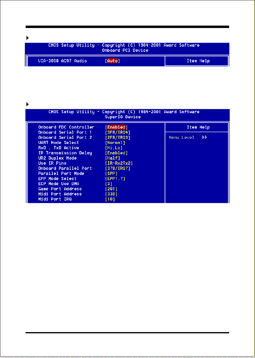
VIA OnChip PCI Device
VIA-3058 AC97 Audio: This item allows you to decide to Auto/disable the
chipset family to support AC97 Audio. The function setting AC97 Audio Codec
states. The system default is Auto.
Super IO Device
Onboard FDC Controller: Select Enabled if your system has a floppy disk
controller (FDC) installed on the system board and you wish to use it. If you
install and-in FDC or the system has no floppy drive, select Disabled in this field.
The choice: Enabled, Disabled.
Onboard Serial Port 1/2: Select an address and corresponding interrupt for
the first and second serial ports.
The choice: 3F8/IRQ4, 2E8/IRQ3, 3E8/IRQ4, 2F8/IRQ3, Disabled, Auto.
UART Mode Select: This filed allows the users to configure what IR mode the
2nd serial port should use. The default is Normal.
The choice: Normal, IrDA and ASKIR.
RxD, TxD Active :This field configures the receive and transmit signals
generated from the IR port. The default is Hi Lo (when UART Mode Select is
not set to Normal).
The choice: Hi Hi, Hi Lo, Lo Hi, and Lo Lo.
Page 4-14
Page 41

BIOS
IR Transmission delay: This item allows you to enabled/disable IR transmission delay.
The choice: Enabled, Disabled.
UR2 Duplex Mode: This item allows you to select IR half/full duplex
function.
The choice: Half, Full.
Use IR Pins: This item allows you to select IR transmission routes, one is
RxD2, TxD2 (COM Port) and the other is IR-Rx2Tx2.
The choice: IR-Rx2Tx2, RxD2, TxD2.
Onboard Parallel port: This field allows the user to configure the LPT port.
The choice: 378/IRQ7, 278/IRQ5, 3BC/IRQ7, Disabled.
Parallel Port Mode: This field allows the user to select the parallel port mode.
The choice: SPP, EPP, ECP, ECP+EPP.
EPP Mode Select: This item allows you to determine the IR transfer mode of
onboard I/O chip.
The Choice: EPP1.9, EPP1.7.
ECP Mode USE DMA: This field allows the user to select DMA1 or DMA3 for the
ECP mode.
The Choice: DMA1, DMA3.
Game Port Address: Select an address for the Game port.
The choice: 201, 209, Disabled.
Midi Port Address: Select an address for the Midi port.
The choice: 290, 300, 330, Disabled.
Midi Port IRQ
Select an interrupt for the Midi port.
The choice: 5, 10.
Page 4-15
Page 42

BIOS
Init Display First: If two video cards are used (1 AGP and 1 PCI) this specifies
which one will be the primary display adapter. The default is PCI Slot.
PCI Slots: PCI video card will be primary adapter.
AGP: AGP video card will be primary adapter.
OnChip USB Controller: USB Controller (Port1)(Port2)(Port3).
The Choice: All Disabled, All Enabled, 1&2 USB Port, 2&3 USB Port, 1&3 USB Port,
1 Port, 2 Port, 3 Port.
USB Keyboard/Mouse Support: Select Enabled if your system contains a
Universal Serial Bus (USB) controller and you have a USB/Mouse keyboard.
The Choice: Enabled, Disabled.
IDE HDD Block Mode: IDE Block Mode allows the controller to access blocks of
sectors rather than a single sector at a time. The default is Enabled.
Enabled: Enabled IDE HDD Block Mode. Provides higher HDD transfer rates.
Disabled: Disable IDE HDD Block Mode.
Page 4-16
Page 43
BIOS
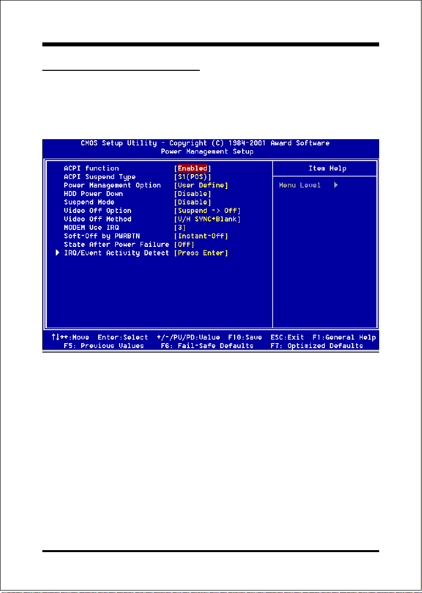
4-5 Power Management Setup
Choose the “POWER MANAGEMENT SETUP” in the CMOS SETUP UTILITY to
display the following screen. This menu allows the user to modify the power
management parameters and IRQ signals. In general, these parameters should not
be changed unless it’s absolutely necessary.
Figure 6: Power Management Setup
ACPI Function: This option allows you to select ACPI Function.
The default is Enabled.
The Choice: Enabled, Disabled.
ACPI Suspend T ype: This item allows you to select S1(POS) or S3(STR) function.
The choice: S1(POS), S3(STR).
Power Management Option: Use this to select your Power Management selection.
The default is User define.
Max. saving: Maximum power savings. Inactivity period is 1 minute in each mode.
Min. saving: Minimum power savings. Inactivity period is 1 hour in each mode.
User define: Allows user to define PM Timers parameters to control power
saving mode.
Page 4-17
Page 44

BIOS
HDD Power Down: When enabled and after the set time of system inactivity,
the hard disk drive will be powered down while all other devices remain active.
The choice: Enabled, Disabled.
Suspend Mode: When enabled and after the set time of system inactivity, all
devices except the CPU will be shut off.
The choice: Enabled, Disabled.
Video Off Option: Tells you what time frame that the video will be disabled under
current power management settings. The default is Suspend->Off.
Always On: Video power off not controlled by power management.
Suspend->Off: Video powers off after time shown in suspend mode setting.
Video Off Method: This option allows you to select how the video will be disabled
by the power management. The default is V/H Sync + Blank
V/H Sync + Blank: System turns off vertical and horizontal synchronization ports
and writes blanks to the video buffer.
DPMS Support: Select this option if your monitor supports the Display Power
Management Signaling (DPMS) standard of the Video
Electronics Standards Association (VESA). Use the software
supplied for your video subsystem to select video power
management values.
Blank Screen: System only writes blanks to the video buffer.
MODEM Use IRQ: Name the interrupt request (IRQ) line assigned to the modem (if
any) on your system. Activity of the selected IRQ always awakens the system.
Default is IRQ 3.
The Choice: N/A, 3, 4, 5, 7, 9, 10, 11
Soft-Off by PWRBTN: Use this to select your soft-off function.
The default is Instant Off.
Instant Off: Turns off the system instantly.
Delay 4 Second : Turns off the system after a 4 second delay. If momentary
press of button, the system will go into Suspend Mode. Press
the power botton again to make system back to work.
Page 4-18
Page 45
BIOS
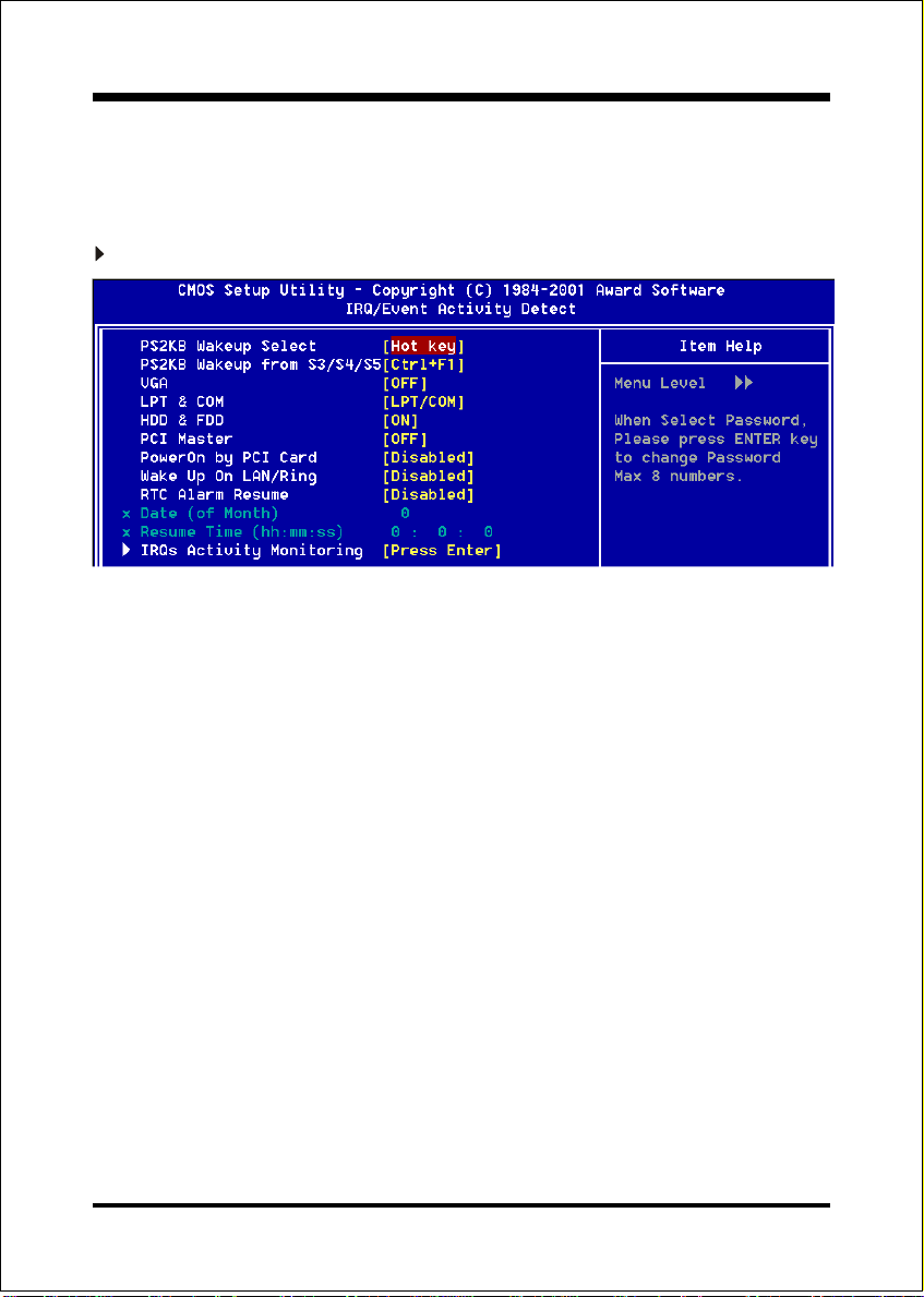
State After Power Failure: This field lets you determine the state that your PC
returns to after a power failure. If set to OFF, the PC will not boot after a power
failure, if set to ON, the PC will restart after a power failure.
IRQ/Event Activity Dectect
PS2KB Wakeup Select : This item allows you to select Hot Key or Password
to wake-up the system by PS2 Keyboard. When select Password, please press
ENTER key to change password max 8 numbers.
PS2KB Wakeup form S3/S4/S5: This item allows you to set a Hot Key to wakeup the system by PS2 Keyboard.
The choice: Disabled, Ctrl+F1, Ctrl+F2, Ctrl+F3, Ctrl+F4, Ctrl+F5, Ctrl+F6,
Ctrl+F7, Ctrl+F8, Ctrl+F9, Ctrl+F10, Ctrl+F11, Ctrl+F12, Power, Wake, Any
key.
Note: Power and Wake are Windows98 Keyboard button.
VGA: When set to On, any event occurring at a VGA port will awaken a system
which has been powered down.
LPT & COM: When set to LPT/COM, any event occurring at a COM(serial)/
LPT (printer) port will awaken a system which has been powered down.
HDD & FDD: When set to On, any event occurring at a hard or floppy drive
port will awaken a system which has been powered down.
PCI Master: When set to Off, any event occurring to the DMA controller will
awaken a system which has been powered down.
Page 4-19
Page 46
BIOS
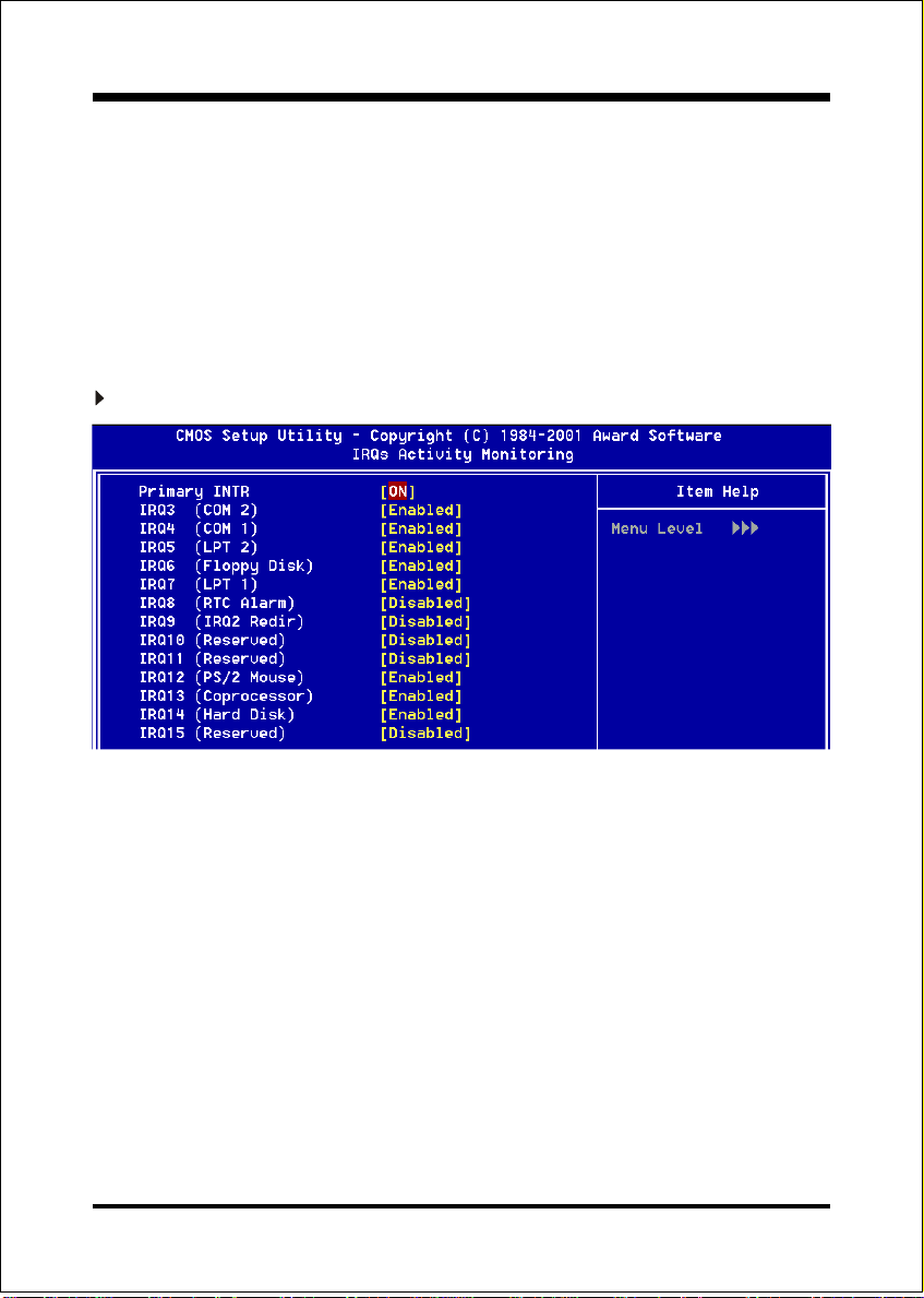
PowerOn by PCI Card: An input signal form PME on the PCI card awakens
the system from a soft off state.
Modem Ring/LAN Resume: When set to Enabled, any event occurring to the
Modem Ring / LAN will awaken a system which has been powered down.
RTC Alarm Resume: When set to Enable rtc alarm resume, you could set the
date (of month) and timer (hh:mm:ss), any event occurring at will awaken a
system which has been powered down.
IRQs Activity Monitoring
Primary INTR: When set to On (default), any event occurring at will awaken a
system which has been powered down.
IRQs 3-15: Allows you to set system to monitor IRQs 3-15 for activity to
awaken system form a power managerment mode.
Page 4-20
Page 47
BIOS
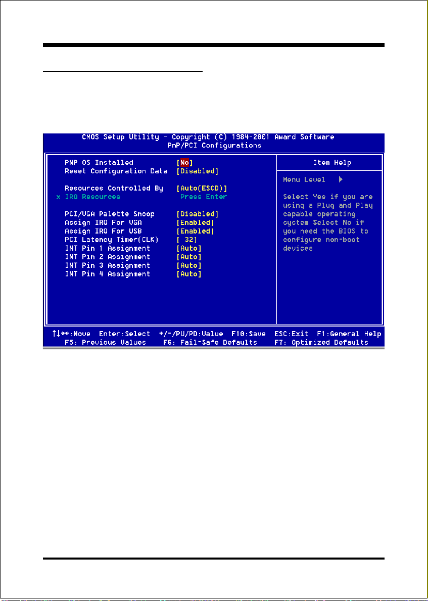
4-6 PNP/PCI Configuration
The PNP/PCI configuration program is for the user to modify the PCI/ISA IRQ
signals when various PCI/ISA cards are inserted in the PCI or ISA slots.
WARNING: Conflicting IRQ’s may cause the system to not find certain devices.
Figure 7: PCI Configuration Setup
PNP OS Installed: Do you have a PNP OS installed on your system. The default
is No.
Reset Configuration Data: This setting allows you to clear ESCD data.
The default is Disabled
Disabled: Normal Setting.
Enabled: If you have plugged in some Legacy cards to the system and they were
recorded into ESCD (Extended System Configuration Data), you can
set this field to Enabled in order to clear ESCD.
Resources Controlled By: Who controlled the system PNP/PCI resources.
The default is Auto.
Page 4-21
Page 48

BIOS
Manual: PNP Card’s resources will be controlled manually. You can set which
IRQ-X and DMA-X are assigned to PCI/ISA PNP or Legacy ISA Cards.
Auto: If your ISA card and PCI card are all PNP cards, BIOS will assign the
interrupt resource automatically.
PCI/VGA Palette Snoop: Leave this field at Disabled.
The choice: Enabled, Disabled.
Assign IRQ For VGA/USB: This item allows BIOS to assign whether IRQ is
with VGA/USB or not. If you have not connect the VGA/USB device. Can
release the IRQ for other device. The default is Enabled.
Enabled: Provides IRQ for VGA/USB device.
Disabled: Release IRQ for other device.
PCI Latency Timer (CLK): The latency timer defines the minimum amount of
time, in PCI clock cycles, that the bus master can retain the ownership of the bus.
The Choice: 0-255.
INT Pin1 to Pin4 Assignment: These settings allow the user to specify what IRQ
will be assigned to PCI devices in the chosen slot. Options available: Auto,3,4,5,7,9,
10,11,12,14 & 15. The defaults are Auto.
Interrupt request are shared as shown the table below:
ATNIBTNICTNIDTNI
1ICP
2ICP
3ICP
4ICP
5ICP
tolSPGA
79CM/79CA
IMPORTANT! If using PCI cards on shared slots, make sure that the drivers support
V
V
V
V
V
V
V
1BSUdraobnO
2BSUdraobnO
“Shared IRQ” or that the cards don’t need IRQ assignments. Conflicts will
arise between the two PCI groups that will make the system unstable or
cards inoperable.
V
V
Page 4-22
Page 49
BIOS
4-7 PC Health Status
31oC/87oF
0oC/32oF
6135 RPM
0 RPM
1.62V
1.52V
4.97V
12.16V
3.35V
2.57V
3.02V
4.89V
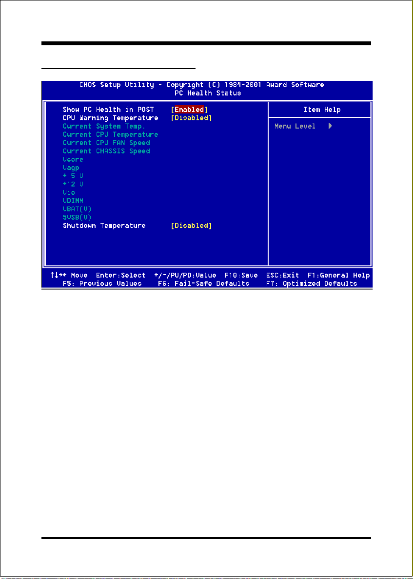
Show PC Health in POST: When enable this function, you can see PC Health in
Post screen.
CPU Warning Temperature: This is the temperature that the computer will respond to an overheating CPU. The default is Disabled.
The Choice: Disabled, 50OC/122OF, 53OC/127OF, 56OC/133OF, 60OC/140OF,63OC/
145OF, 66OC/151OF, 70OC/158OF.
Current System Temperature: This is the Current temperature of the system.
Current CPU Temperature: This is the Current temperature of the CPU.
Current CPU/Chassis FAN Speed: The current CPU/Chassis fan speed in RPMs.
Vcore: The voltage level of the CPU(Vcore).
Vagp: The voltage level of Power supplied to AGP card.
1.52V: for 4X AGP card.
3.3V : for 2X AGP card.
Page 4-23
Page 50

BIOS
5V, 12V, VBAT(V), 5VSB(V): The voltage level of the switch power supply.
Vio: The voltage level of the CPU Vio.
VDIMM: The voltage level of the DRAM.
Shutdown Temperature: This is the temperature that the computer will turn off
the power to combat the effects of an overheating system. (requires ACPI to be
enabled in Power Management BIOS and ACPI compliant operating system.) The
default is Disabled.
Options available are 60oC/140oF to 75oC/167oF in increments of 5oC.
Page 4-24
Page 51
BIOS
4-8 Frequency/V oltage Control
1.75 V
1.75 V
2.50 V
1.50 V
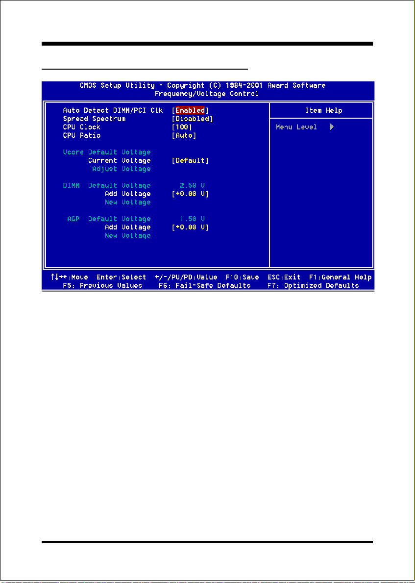
Auto Detect DIMM/PCI Clk: When enabled the motherboard will automatically
disable the clock source for a DIMM socket which does not have a module in it.
Same applies for PCI slots. This setting will reduce the EMI. The default is Enabled.
Spread Spectrum: This item allows you to enable/disable the spread spectrum
modulate.
CPU Clock: The mainboard is designed to set the CPU clock via BIOS. This
item allows you to adjust CPU clock 1MHz by step.
Note: Overclocking failure will cause system No display problem. At this
moment, please press “Insert” key to back to the initial or default
setting to boot up your system.
CPU Ratio: This item allows you to select the CPU ratio. If the CPU ratio is
fixed. This item was no function.
The choice: Auto, [x6]...[x15].
Page 4-25
Page 52

BIOS
CPU Vcore Voltage: This item allows you to increase the CPU Vcore Voltage.
The option: Default, ±0.025V increment.
DIMM Voltage: This item allows you to increase the DIMM Voltage.
The option: +0.1V increment.
AGP Voltage: This item allows you to increase the AGP Voltage. (Applicable
when you plug in AGP card).
The option: +0.1V increment.
Page 4-26
Page 53

BIOS
4-9 Defaults Menu
Selecting “Defaults” from the main menu shows you two options which are
described below
Load Fail-Safe Defaults
When you press <Enter> on this item you get a confirmation dialog box with a
message similar to:
Load Fail-Safe Defaults (Y/N) ? N
Pressing ‘Y’ loads the BIOS default values for the most stable, minimal-performance system operations.
Load Optimized Defaults
When you press <Enter> on this item you get a confirmation dialog box with a
message similar to:
Load Optimized Defaults (Y/N) ? N
Pressing ‘Y’ loads the default values that are factory settings for optimal performance system operations.
Page 4-27
Page 54

BIOS
4-10 Supervisor/User Password Setting
You can set either supervisor or user password, or both of then. The differences
between are:
supervisor password : can enter and change the options of the setup menus.
user password : just can only enter but do not have the right to change the
options of the setup menus. When you select this function, the following message
will appear at the center of the screen to assist you in creating a password.
ENTER P ASSWORD:
Type the password, up to eight characters in length, and press <Enter>. The password typed now will clear any previously entered password from CMOS memory.
You will be asked to confirm the password. Type the password again and press
<Enter>. You may also press <Esc> to abort the selection and not enter a password.
To disable a password, just press <Enter> when you are prompted to enter the
password. A message will confirm the password will be disabled. Once the password is disabled, the system will boot and you can enter Setup freely.
P ASSWORD DISABLED.
When a password has been enabled, you will be prompted to enter it every time you
try to enter Setup. This prevents an unauthorized person from changing any part of
your system configuration.
Additionally, when a password is enabled, you can also require the BIOS to request
a password every time your system is rebooted. This would prevent unauthorized
use of your computer.
You determine when the password is required within the BIOS Features Setup Menu
and its Security option. If the Security option is set to “System”, the password will
be required both at boot and at entry to Setup. If set to “Setup”, prompting only
occurs when trying to enter Setup.
Page 4-28
Page 55

BIOS
4-11 Exit Selecting
Save & Exit Setup
Pressing <Enter> on this item asks for confirmation:
Save to CMOS and EXIT (Y/N)? Y
Pressing “Y” stores the selections made in the menus in CMOS – a special section
of memory that stays on after you turn your system off. The next time you boot
your computer, the BIOS configures your system according to the Setup selections stored in CMOS. After saving the values the system is restarted again.
Exit Without Saving
Pressing <Enter> on this item asks for confirmation:
Quit without saving (Y/N)? Y
This allows you to exit Setup without storing in CMOS any change. The previous
selections remain in effect. This exits the Setup utility and restarts your computer.
Page 4-29
Page 56

BIOS
Page Left Blank
Page 4-30
Page 57
Easy Driver Installation
Drivers Installation
Section 5
Driver Installation
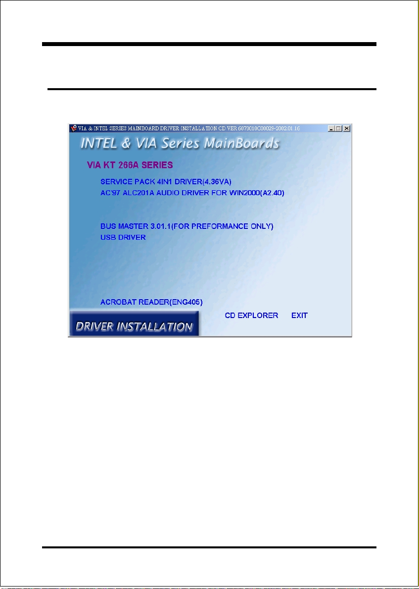
Insert the bundled autorun driver CD-disk.
Step 1 : Click “SERVICE PACK 4IN1 DRIVER”. Install all components
recommended.
Step 2 : Click “AC’97 ALC201A AUDIO DRIVER” to install Audio Sound
Driver.
Step 3 : Click “BUS MASTER” to install BusMaster PCI IDE.
(For performance only).
Step 4 : Click “USB DRIVER” to install USB Driver.
Page 5-1
Page 58

Drivers Installation
Page Left Blank
Page 5-2
Page 59
Appendix
Appendix A
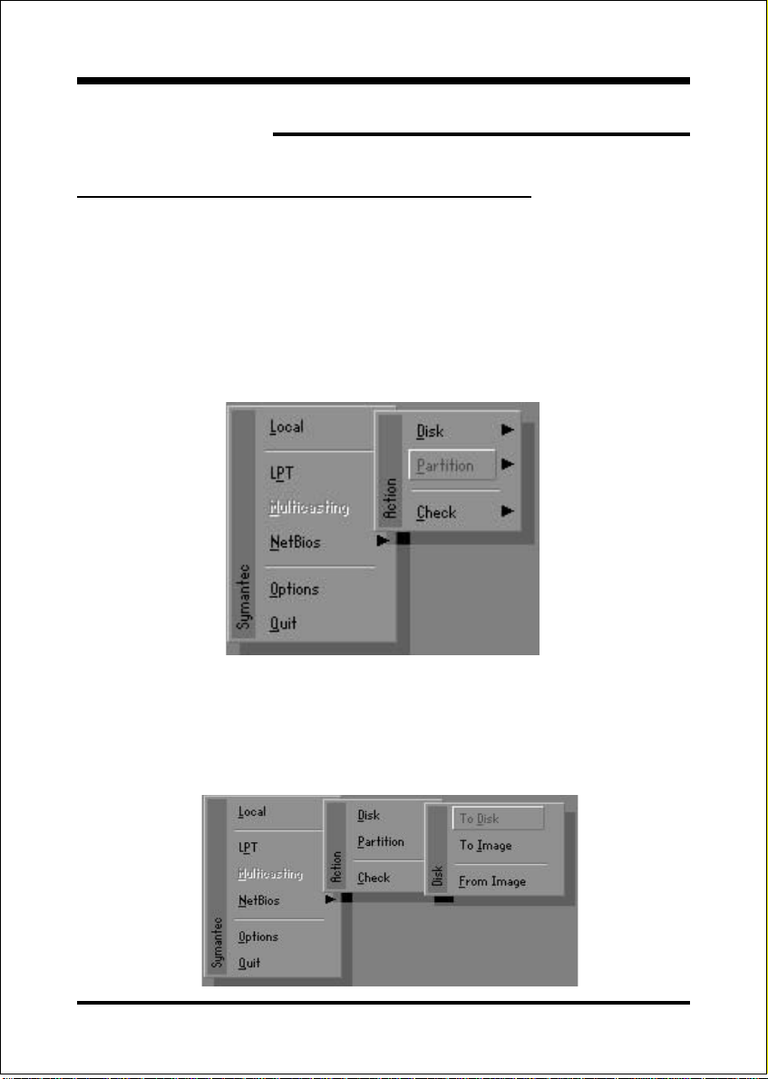
A-1 GHOST 5.1/6.03 Quick User’s Guide (Optional)
Installation is very easy. You only need to copy the Ghost5 folder or
Ghost.exe to your hard disk.
The current market version is for single Client, so the LPT and NetBios
portions will not be explained further.
Description of Menus
Ghost clones and backs up Disk and Partition.
In which Disk indicates hard disk options
Partition indicates partition options
Check indicates check options
Disk
A-1
Page 60
Appendix
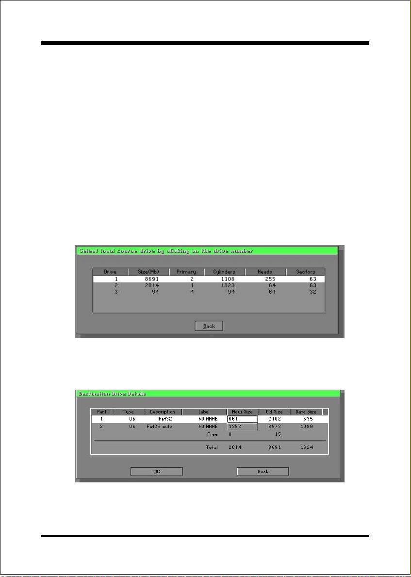
There are 3 hard disk functions:
1. Disk To Disk (disk cloning)
2. Disk To Image (disk backup)
3. Disk From Image (restore backup)
Important!
1. To use this function, the system must have at least 2 disks. Press the
Tab key to move the cursor.
2. When restoring to a destination disk, all data in that disk will be
completely destroyed.
Disk To Disk (Disk Cloning)
1. Select the location of the Source drive.
2. Select the location of the Destination drive.
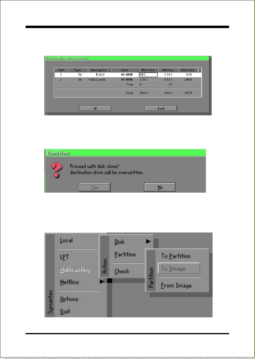
3. When cloning a disk or restoring the backup, set the required partition
size as shown in the following figure.
A-2
Page 61
Appendix
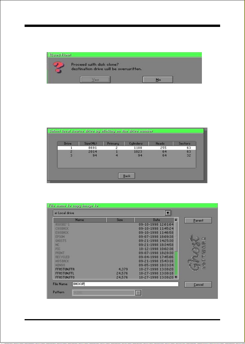
4. Click OK to display the following confirmation screen. Select Yes to
start.
Disk To Image (Disk Backup)
1. Select the location of the Source drive.
2. Select the location for storing the backup file.
A-3
Page 62
Appendix
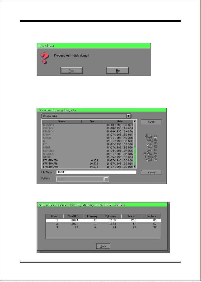
3. Click OK to display the following confirmation screen. Select Yes to
start.
Disk From Image (Restore Backup)
1. Select the Restore file.
2. Select the Destination drive of the disk to be restored.
A-4
Page 63
Appendix
3. When restoring disk backup, set the required partition size as shown in
the following figure.
4. Click OK to display the following confirmation screen. Select Yes to
start.
Partition
A-5
Page 64
Appendix
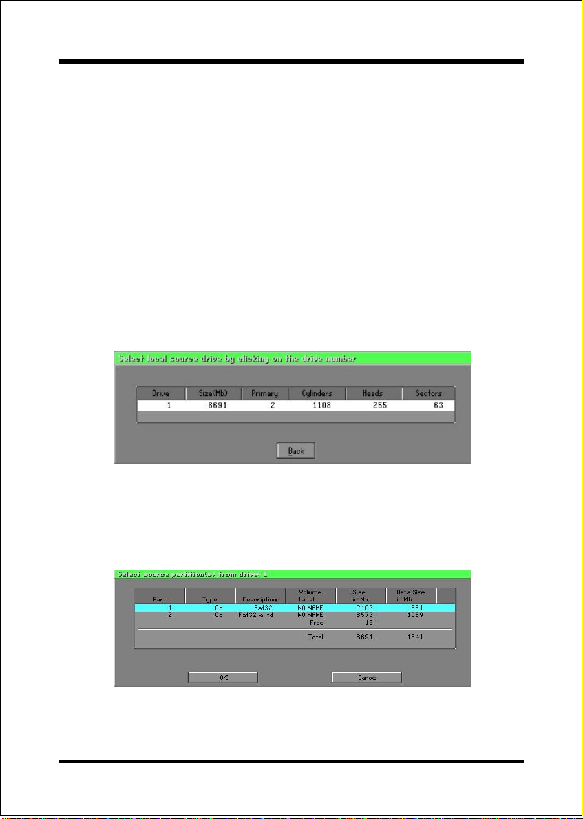
There are 3 partition functions:
1 . Partition To Partition (partition cloning)
2. Partition To Image (partition backup)
3. Partition From Image (restore partition)
Partition To Partition (Partition Cloning)
The basic unit for partition cloning is a partition. Refer to disk cloning for
the operation method.
Partition To Image (Partition Backup)
1. Select the disk to be backed up.
2. Select the first partition to be backed up. This is usually where the
operating system and programs are stored.
A-6
Page 65
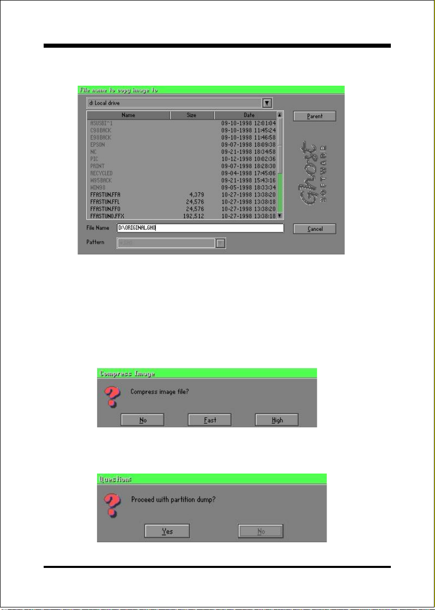
3. Select the path and file name for storing the backup file.
4. Is the file compressed? There are 3 options:
(1) No: do not compress data during backup
(2)Fast: Small volume compression
Appendix
(3)High: high ratio compression. File can be compressed to its minimum,
but this requires longer execution time.
5. During confirmation, select Yes to start performing backup.
A-7
Page 66
Appendix
Partition From Image (Restore Partition)
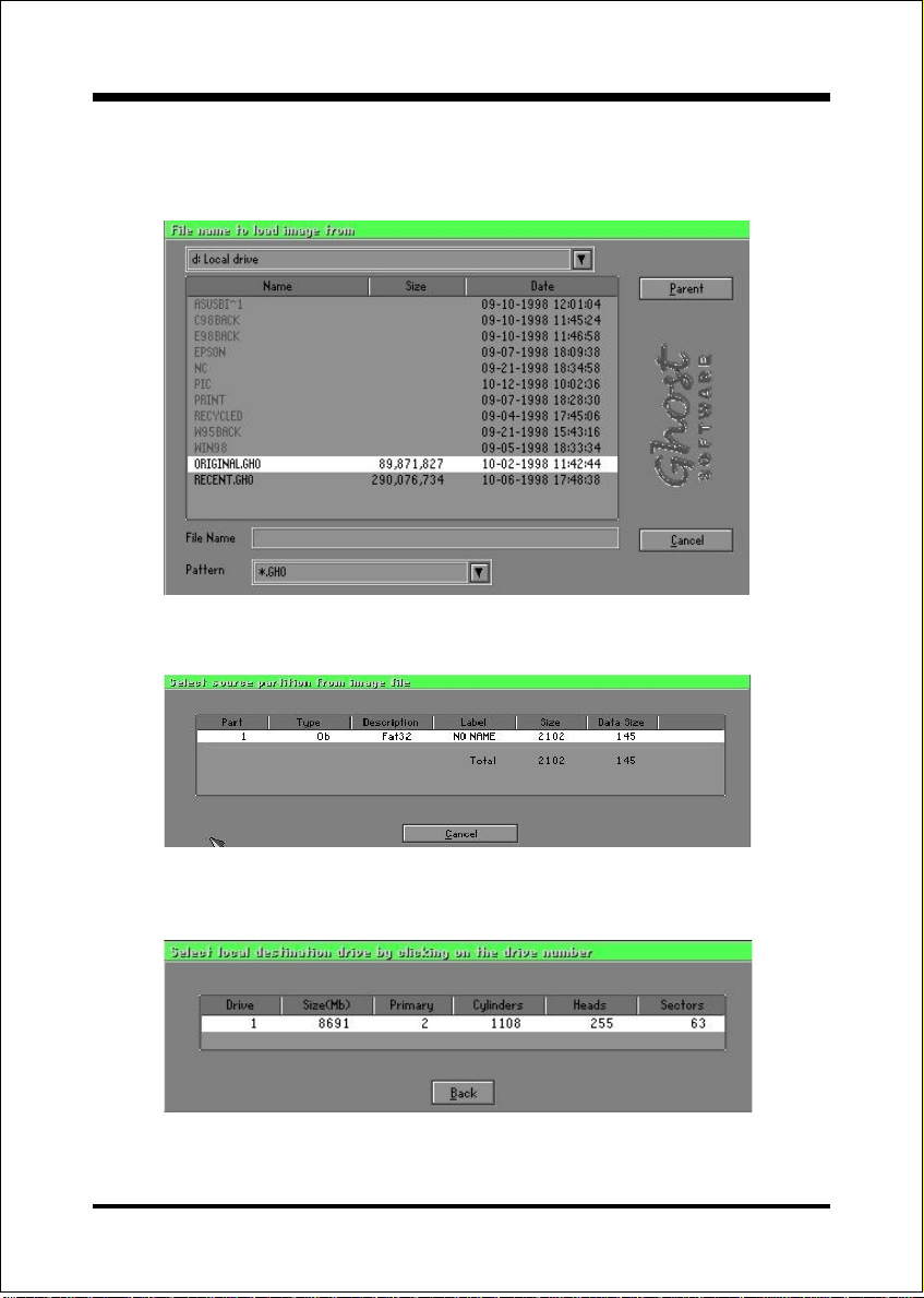
1. Select the backup file to be restored.
2. Select the source partition.
3. Select the disk to be restored.
A-8
Page 67
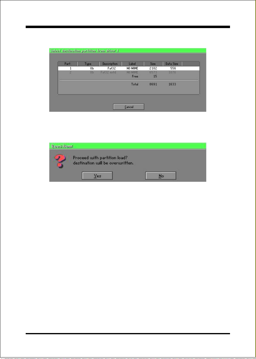
4. Select the partition to be restored.
5. Select Yes to start restoring.
Appendix
Check
This function checks the hard disk or backup file for backup or
restoration error due to FAT or track error.
A-9
Page 68

Appendix
How to Reinstall Windows in 2 Minutes
This chapter teaches you how to set your computer properly and, if
necessary, reinstall Windows in 2 minutes. Ghost can use different
methods to complete this task. The following two sections explain the
creation of the emergency Recover Floppy and Recover CD:
Emergency Recover Floppy
Divide a hard disk into two partitions. The first partition is for storing the
operating system and application programs. The second partition is for
backing up the operating system and data. The size of the partition can be
set according to the backup requirements. For example, the Windows
operating system needs 200MB of hard disk space, while the complete
Office installation requires 360MB. The remaining space can be used to
store other data.
After installing Windows, use Ghost to create a backup of the source system
and store the file (Image file) in drive D. The file is named as Original.gho.
Then, create a recover floppy disk containing:
Bootable files (Command.com, Io.sys, and MSDOS.SYS )
Config.sys (configuration setup file)
Autoexec.bat (auto-execution batch file)
Ghost.exe (Ghost execution file)
There are two ways to set the content of the recover floppy for restoration:
(1)To load Windows automatically after booting, set the Autoexec.bat
command as:
Ghost.exe clone, mode=pload, src=d:\original.gho:2,dst=1:1 -fx -sure -rb
Description: Runs the restore function automatically using the Image
File. After execution, it exits Ghost and boots the system
automatically.
Refer to the [Introducing Ghosts Functions].
A-10
Page 69

Appendix
(2)After booting, the screen displays the Menu. Select Backup or Restore:
Since the user may install other applications in the future, he/she may
design Autoexec.bat as a Menu to back up or restore the userdefined Image file as follows:
BackupBackup
Backup
BackupBackup
))
)
))
Back up Windows and application programs as a file (Recent.
gho). Command is:
Ghost –clone,mode=pdump,src=1:1,dst=d:\Recent.gho -fx sure -rb
RestoreRestore
Restore
RestoreRestore
))
)
))
Restore types include [General Windows] and [Windows and
Application Programs]. If you select [General Windows],
the system is restored to the general Windows operation
condition. The command is:
Ghost.exe -clone,mode=pload,src=d:\Original.gho,dst=1:1 -fx
-sure -rb
If you select [Windows and Application Programs], the latest
backup file (Recent.gho) is restored, skipping the installation
and setup of application programs.
For description of relevant parameters, refer to [Introducing Ghosts
Functions].
For more information about menu design, refer to Config.sys and
Autoexec.bat under /Menu in the CD. You can also create a backup CD
containing Ghost.exe and these two files.
A-11
Page 70

Appendix
Recover CD
In recent years, well-known computer manufacturers (such as IBM, Acer,
Compaq, etc.) bundle Recover CDs with their computers to reduce the
cost resulting from servicing, while at the same time increasing their market
competitiveness.
The following is a simple guide to how to create a recover CD:
1. For extremely easy creation of the recover floppy disk, use the copy
program for example “Easy CD Creator “ (Note 2). First, create a
recover floppy disk containing:
Bootable files (Command.com and Io.sys and MSDOS.SYS)
Config.sys (Configuration setup file)
Autoexec.bat (Auto-execution batch file)
Mscdex.exe (CD-Rom execution file)
Ghost.exe (Ghost execution file)
Oakcdrom.sys (ATAPI CD-ROM compatible driver)
The content of Config.sys is:
DEVICE=Oakcdrom.sys /d:idecd001
The content of Autoexec.bat includes:
MSCDEX.EXE /D:IDECD001 /L:Z
Ghost.exe clone,mode=load,src=z:\original.gho,dst=1 -sure -rb
2. Write the backup image file (original.gho) of the entire hard disk or
partition into the recover CD. Use the Recover CD to boot up the
system and restore the backup files automatically.
For description of relevant parameters, refer to [Introducing Ghosts
Functions].
Note: For more details regarding the creation program and method for
creating the recover CD, please refer to the legal software and
relevant operation manual.
A-12
Page 71

Appendix
Ghost Command Line Switches Reference
Ghost may be run in interactive or in batch mode. Batch mode is useful for automating installations for backups using Ghost. Most of the Ghost switches are used to
assist with batch mode operation. To list switches from Ghost, type ghost.exe -h.
-clone
The full syntax for this switch is:
clone,MODE={copy|load|dump|pcopy|pload|pdump},SRC=
{drive|file|drive:partition|,DST={drive|file|drive:partition},SZE{F|L|n=
{nnnnM|nnP|F|V}}
Clone using arguments. This is the most useful of the batch switches
and has a series of arguments that define:
a) MODE This defines the type of clone command to be used:
COPY disk to disk copy
LOAD file to disk load
DUMP disk to file dump
PCOPY partition to partition copy
PLOAD file to partition load
PDUMP partition to file dump
b) SRC This defines the source location for the operation:
Mode Meaning:
COPY/
DUMP Source drive (e.g, 1 for drive one)
LOAD
PCOPY/
PDUMP Source partition e.g, 1:2 indicates the second partition
PLOAD Partition image filename or device and partition
Disk image filename or device (e.g, g:\Images\system2.img)
on drive one.
number. Example: g:\images\disk1.img:2 indicates the
second partition in the Image file.
A-13
Page 72

Appendix
c) DST This defines the destination location for the operation:
Mode Meaning
COPY/
LOAD Destination drive (e.g, 2 for drive two)
DUMP
PCOPY/
PLOAD Destination partition,(e.g, 2:2 indicates the second
PDUMP Partition image filename (e.g, g:\images\part1.img).
d) SZEy Used to set the size of the destination partitions for
Disk image filename or device,(e.g, g:\images\system2.img)
partition on drive two).
either a disk load or disk copy operation.
Available y Options:
F Resizes the first partition to maximum size allowed based
on file system t type.
L Resizes the last partition to maximum size allowed based on
file system type.
n=xxxxM - indicates that the n?h destination partition is to have a size
of xxxx Mb. (e.g, SZE2=800M indicates partition two is to
have 800 mb.) n=mmP - indicates that the n?h destination
partition is to have a size of mm percent of the target disk.
n=F - indicates that the n?h destination partition is to remain
fixed in size.
n=V - Indicates that the partition will be resized according to the
following rules:
Rule 1 - If the destination disk is larger than the original
source disk, then the partition(s) will be expanded to have
the maximum amount of space subject to the free space
available and the partition type (e.g, FAT16 partitions will
have a maximum size of 2048Mb.)
Rule 2 - If the destination disk is smaller than the original
source disk, (but still large enough to accommodate the
data from the source disk), the free space left over after the
A-14
Page 73

Appendix
data space has been satisfied will be distributed between the
destination partitions in proportion to the data usage in the
source partitions Someexamples follow that will help
illustrate:
-fx flag Exit. Normally when Ghost has finished copying a new
system to a disk, it prompts the user to reboot with a press
Ctrl-Alt-Del to reboot window. However, if Ghost is being
run as part of a batch file it is sometimes useful to have it
just exist back to the DOS prompt after completion so that
further batch commands may be processed. -fx enables
this. See -rb for another option on completing a clone.
-ia Image All. The Image All switch forces Ghost to do a
sector by sector copy of all partitions. When copying a
partition from a disk to an image file or to another disk,
Ghost examines the source partition and decides whether to
copy just the files and directory structure, or to do an
image (sector by sector) copy. If it understands the internal
format of the partition it defaults to copying the files and
directory structure. Generally this is the best option, but
occasionally if a disk has been set up with special hidden
security files that are in specific positions on the partition ,
the only way to reproduce them accurately on the target
partition is via an image or sector-by-sector copy.
-span enables spanning across volumes.
-split=x splits image file into ‘x’ Mb? Mb spans. Use this to create a
‘forced’ size volume set. For example, if you would like to
force smaller image files from a 1024 Megabyte drive, you
could specify 200 megabyte segments.For example, ghost.
exe -split=200 will divide the image into 200 Megabyte
segments.
-sure use the -sure switch in conjunction with -clone to avoid
being prompted with the final ‘Proceed with disk clone
destination drive will be overwritten?’ question. This
command is useful in batch mode.
A-15
Page 74

Appendix
Example 1:
To copy drive one to drive two on a PC, without final prompt if OK to
proceed.
ghost.exe -clone,mode=copy,src=1,dst=2 –sure
Example 2:
To connect via NetBIOS to another PC running Ghost in slave mode, and
dump a disk image of local drive two to the remote file c:\drive2.gho
ghost.exe -clone,mode=dump,src=2,dst=C:\drive2.gho -nbm
Note: The slave Ghost can be started with ghost –nbs
Example 3:
To copy drive one, second partition on a PC to drive two, first parti-tion
the same PC, without final prompt
ghost.exe -clone,mode=pcopy,src=1:2,dst=2:1 –sure
Example 4:
To dump the second partition of drive one to an image file on a mapped
drive g:
ghost.exe -clone,mode=pdump,src=1:2,dst=g:\part2.gho
Example 5:
To load partition 2 from a two-partition image file on a mapped drive g:
onto the second partition of the local disk
ghost -clone,mode=pload,src=g:\part2.gho:2,dst=1:2
Example 6:
To load drive 2 from an image file and resize the destination partitions into a
20:40 allocation
ghost.exe -clone,mode=load,src=g:\2prtdisk.gho,dst=2,sze1=60P,
sze2=40P
A-16
Page 75
Appendix
Appendix B
B-1 Update Y our system BIOS
Download the xxxxx.EXE file corresponding to your model form the our website to
an empty directory on your hard disk or floppy. Run the downloaded xxxxx.EXE
file and it will self extract. Copy these extracted files to a bootable DOS floppy
disk.
Note: The DOS floppy disk should contain NO device drivers or other programs.
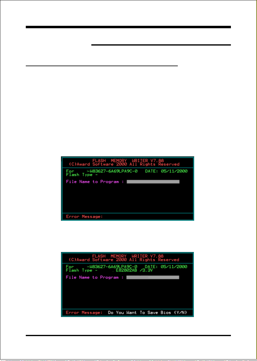
1. Type “A:\AWDFLASH and press <Enter> Key.
2. You will see the following setup on screen.
3. Please key in the xxxxx.bin BIOS file name.
XXXX
4. If you want to save the previous BIOS data to the diskette, please key in [Y],
otherwise please key in [N].
XXXX
XXXXX
xxxxx.bin
B-1
Page 76
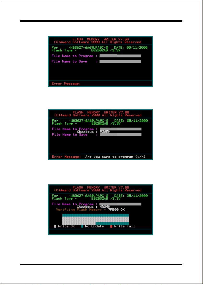
Appendix
5. Key in File Name to save previous BIOS to file.
XXXX
XXXXX
xxxxx.bin
xxxxx.bin
6. Are you sure to program (y/n), please key in [Y] to start the programming.
XXXX
XXXXX
xxxxx.bin
xxxxx.bin
7. The programming is finished.
B-2
F1 : Reset
XXXX
XXXXX
xxxxx.bin
F10 : Exit
Page 77
Appendix
Appendix C
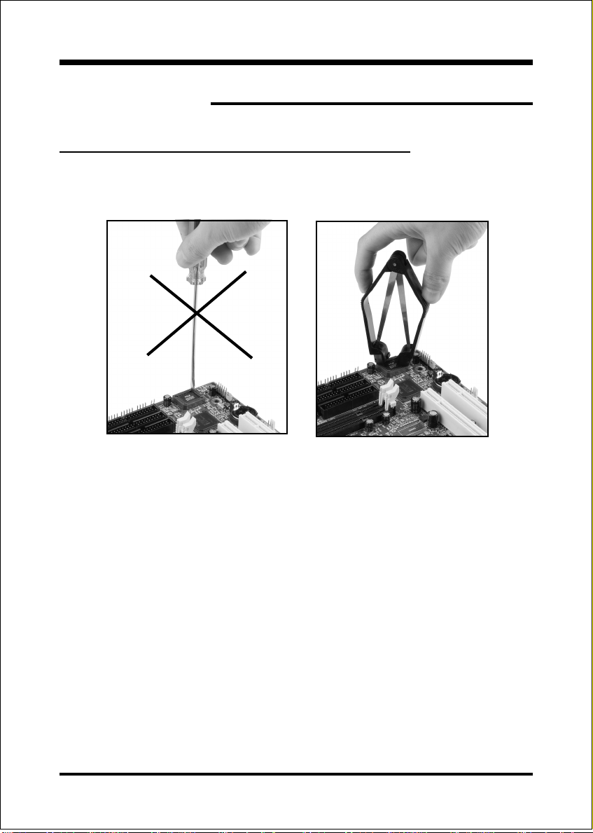
C-1 EEPROM BIOS Remover
Do not remove the BIOS chip, unless instructed by a technician and only with a
PLCC IC extractor tool.
The BIOS socket may be damaged if using an improper method to
replace the BIOS chip.
C-1
Page 78

Appendix
Page Left Blank
C-2
Page 79
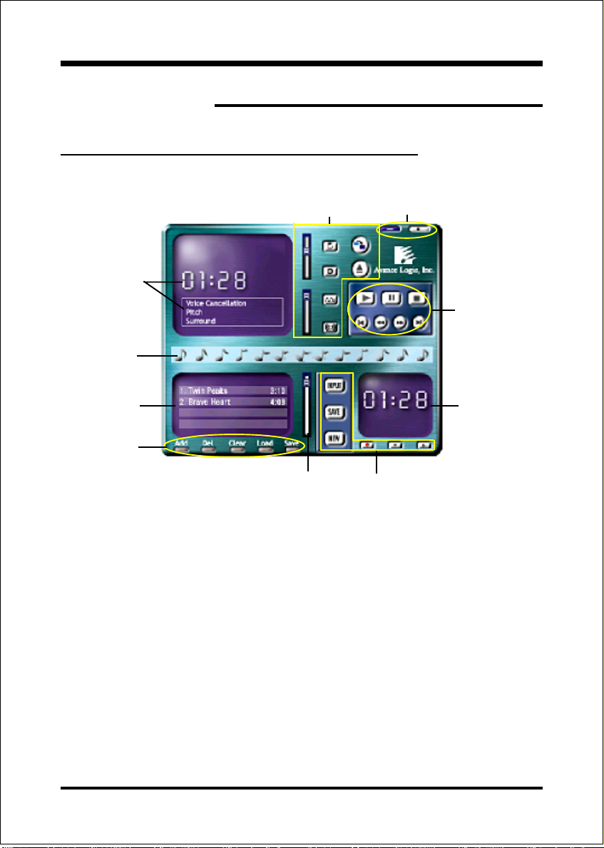
D-1 Avance® Media Player User’s Guide
®
Avance
Media Player Platform
Appendix
Appendix D
B
7
3
1
8
4
A
D
E
F
5
2
6
G
H
Functional Descriptions
A. Playback Windows Display
Playback windows displays the following mode information:
1. Playback Time Display
2. Voice Cancellation Mode Display
3. Pitch Mode Display
4. Surround Sound Mode Display
J
C
I
B. Playback Function Controls
There are 8 selectable functions for the playback:
1. Volume control High/Low Adjustment Bar.
2. Pitch control 4-step High/Low Adjustment Bar.
D-1
Page 80

Appendix
3. Repeat mode Choice of Repeat, All Repeat, Random or No
Repeat Mode.
4. Mute Mute On/Off Mode select.
5. Voice cancellation Voice Cancellation On/Off Mode select for
Karaoke.
6. Surround mode A total of 26 Surround Sound mode select as
shown in the table below.
edomdnuorruSedomdnuorruS
cireneGrodirrocenotS
deddaPyellA
mooRtserroF
moorhtaBytiC
moorgniviLniatnuoM
enotSyrrauQ
muirotiduAnialP
trecnoCtolgnikraP
evaCepipreweS
anerAretawrednU
ragnaHgurD
tepraCyzziD
yawllaHlacigolohcysP
7. Skin change Media Player Skin Type select.
8. Open Open file formats including MP3, CDA, MDI, WAV
& WMA support.
C. Playback Controls
The playback controls include “Play”, “Pause”, “Stop”, “Previous”, “Backward”,
“Forward”, & “Next”.
D. Seeking bar
Display Animated Playback Status
E. Title/Play List Windows
Display Currently Selected Title(s)
D-2
Page 81

Appendix
F. Title/Play List Edit Controls
There title/play list controls include “Add”, “Del”, “Clear”, “Load”, & “Store”.
1. Add Add to the Title/Play List.
2. Del Remove form the Title/Play List.
3. Clear Clear the Title/Play Lost.
4. Load Load Title/Play List.
5. Store Save Title/Play List.
G. Title/Play List Scroll bar
Scroll Up/Down the Title/Play List.
H. Recording Function Controls
The recording function controls include “Input”, “Save:, “New”, “Rec”, “Stop”,
& “Play”.
1. Input Input soruce select.
2. Save Save to file.
3. New Open new file & select format includes Sampling
Rate, Sampling bit, Mono or Stereo.
4. Rec Start Rec.
5. Stop Stop Rec.
6. Play Playback Rec file.
I. REC/Playback Time Display
Displays REC/Playback Time.
J. Platform Display Panel Controls
The platform display panel control include “Minimize” & “Close”.
1. Minimize Minimize Platform Display Panel.
2. Close Close/Exit Platform Display Panel.
D-3
Page 82

Appendix
Page Left Blank
D-4
 Loading...