

Page 1

TRADEMARK
All products and company names are trademarks or registered
trademarks of their respective holders.
These specifications are subject to change without notice.
Manual Revision 1.0
April 05, 2004
User’User’
User’User’
User’
ss
ss
s
ManualManual
ManualManual
Manual
60000024SGM10
SiS SiS
SiS SiS
SiS
661FX661FX
661FX661FX
661FX
mainboard mainboard
mainboard mainboard
mainboard
for Intel Socket 478 processorfor Intel Socket 478 processor
for Intel Socket 478 processorfor Intel Socket 478 processor
for Intel Socket 478 processor
Page 2

ii
DISCLAIMER OF WARRANTIES:
THERE ARE NO WARRANTIES WHICH EXTEND BEYOND THE
DESCRIPTION ON THE FACE OF THE MANUFACTURER LIMITED
WARRANTY. THE MANUFACTURER EXPRESSLY EXCLUDES ALL
OTHER WARRANTIES, EXPRESS OR IMPLIED, REGARDING ITS
PRODUCTS; INCLUDING ANY IMPLIED WARRANTIES OF
MERCHANTABILITY, FITNESS FOR A PARTICULAR PURPOSE OR
NONINFRINGEMENT. THIS DISCLAIMER OF WARRANTIES SHALL
APPLY TO THE EXTENT ALLOWED UNDER LOCAL LAWS IN THE
COUNTRY PURCHASED IN WHICH LOCAL LAWS DO NOT ALLOW
OR LIMIT THE EXCLUSION OF THE IMPLIED WARRANTIES.
Page 3

iii
Table of Contents
Section 1 Introduction
Package Contents ...................................................... 1-1
Intel Pentium 4 Processors......................................... 1-2
Ultra ATA66/100/133 .................................................. 1-2
Hardware Monitoring ................................................. 1-2
LAN ............................................................................ 1-2
I/O Shield Connector.................................................. 1-3
Power-On/Off (Remote) .............................................. 1-3
System Block Diagram ............................................... 1-4
Section 2 Features
Mainboard Features ................................................... 2-1
Section 3 Installation
Mainboard Layout ..................................................... 3-2
Easy Installation Procedure
CPU Installation ......................................................... 3-3
Jumper Settings .......................................................... 3-5
System Memory Configuration .................................. 3-6
Expansion slots .......................................................... 3-8
Device Connectors..................................................... 3-10
External Modem Ring-in Power ON and
Keyboard Power ON Function (KBPO) ..................... 3-15
ACPI S3 (Suspend To RAM) Function .................... 3-16
Section 4 BIOS Setup
Main Menu ................................................................ 4-1
Standard CMOS Setup ............................................... 4-2
Page
Page 4

iv
Advanced BIOS Features .......................................... 4- 3
Advanced Chipset Features ...................................... 4- 6
Integrated Peripherals ................................................ 4- 9
Power Management Setup ......................................... 4- 14
PNP/PCI Configuration Setup .................................... 4- 18
PC Health Status ........................................................ 4- 20
Power BIOS Features ................................................. 4- 21
Defaults Menu ........................................................... 4- 23
Supervisor/User Password Setting ............................ 4- 24
Exit Selecting .............................................................. 4- 25
Section 5 Driver Installation
Easy Driver Installation .............................................. 5- 1
Realtek Sound Manager Quick User guide ................ 5- 2
Appendix Appendix A
Realtek Media Player User’s Guide ............................ A- 1
Appendix B
Update Your System BIOS ......................................... B- 1
Appendix C
EEPROM BIOS Remover ........................................... C- 1
Appendix D
GHOST 7 Quick User’s Guide (Optional) ................... D- 1
Page 5
Introduction
Page 1-1
Section 1
INTRODUCTION
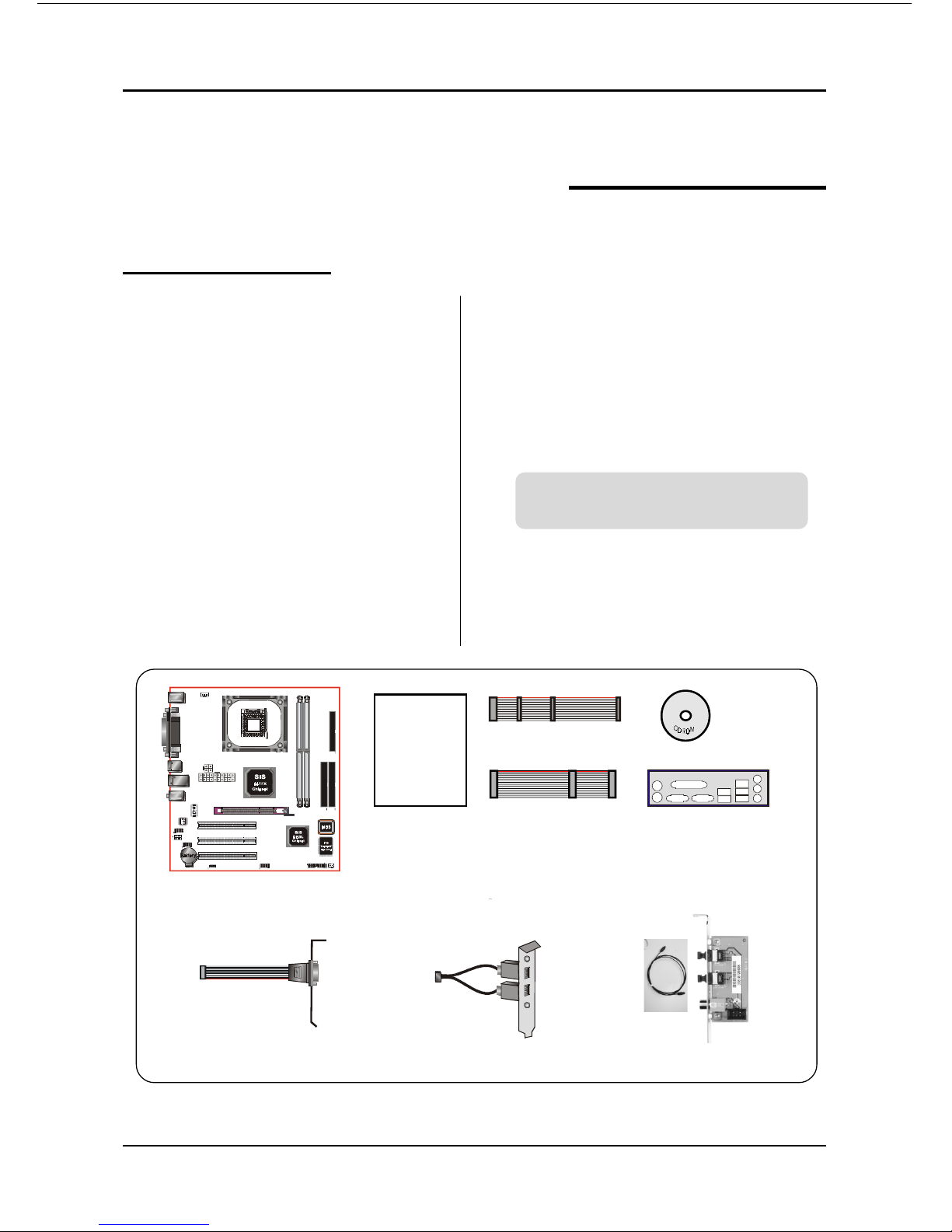
Package Contents
A
B
USER’S
MANUAL
G
F
C
D
E
Contents
A. Mainboard
B. User’s manual
C. Floppy disk drive cable
D. HDD drive cable
E. CD (drivers and utilities)
F. I/O Shield
Optional Items
G. COM port cable
H. Extra USB2.0 port cable
I. S/PDIF Module
If you need the optional item, please
contact your dealer for assistance.
H
I
Page 6

Introduction
Page 1-2
Intel® Pentium® 4 processors
The Pentium 4 processor is designed to deliver performance across applications and
usages where end-users can truly appreciate and experience the performance. These
applications include Internet audio and streaming video, image processing, video
content creation, speech, 3D, CAD, games, multimedia, and multi-tasking user
environments. The Pentium 4 processor delivers this world-class performance for
consumer enthusiasts and business professional desktop PC users as well as for
entry-level workstation users.
Intel adds support for Hyper-Threading Technology to the Pentium 4 processor
family. HT Technology allows a single, physical Pentium 4 processor to function as
two logical processor for next generation multi threaded application.
For more information about all the new features the Pentium 4 delivers check
out the Intel website at http://www.intel.com
Accelerated Graphics Port (AGP)
The AGP slot on the board is compliant with the new AGP 3.0 specification. This
new specification enhances the functionality of the original AGP specification by
allowing 8X data transfers ( 8 data samples per clock) resulting in maximum band-
width of 2.1GB/s. Only 1.5V AGP cards are supported.
Ultra ATA/66/100/133
The board provides two independent ATA133 IDE controllers, supporting standard
programmable input/output (PIO) and Direct Memory Access (DMA) mode
operations, as well as UltraDMA-133/100/66/33 standards for a maximum data
transfer rate of 133MB/sec per channel.
Hardware Monitoring
Hardware monitoring enables you to monitor various aspects of the system operation
and status. The features include CPU temperature, voltage and fan speed in RPMs.
LAN
This mainboard is optionally mounted with LAN chipset. It allows the mainboard to
connect to a local area network by means of a network hub.
Page 7
Introduction
Page 1-3
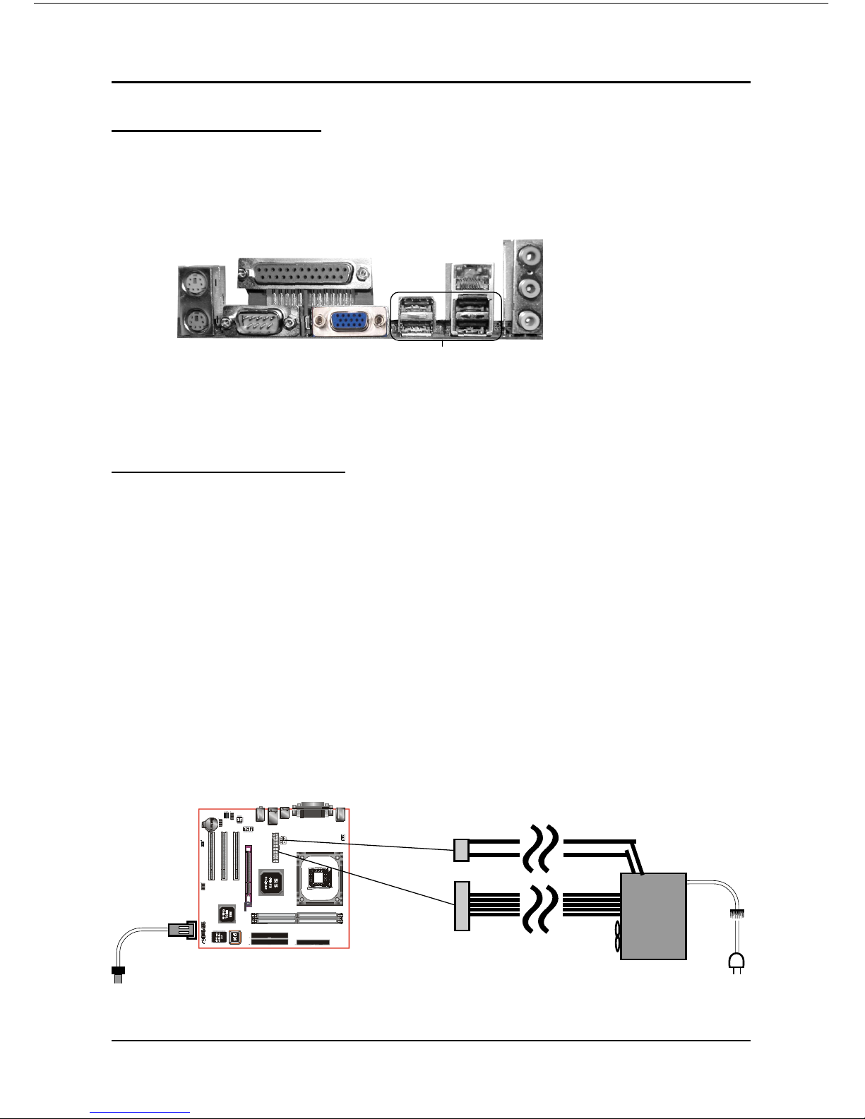
I/O Shield Connector
The I/O back panel for this mainboard is shown below (Figure 1). When installing
the mainboard into the computer case, use the bundled I/O shield to protect this
back panel.
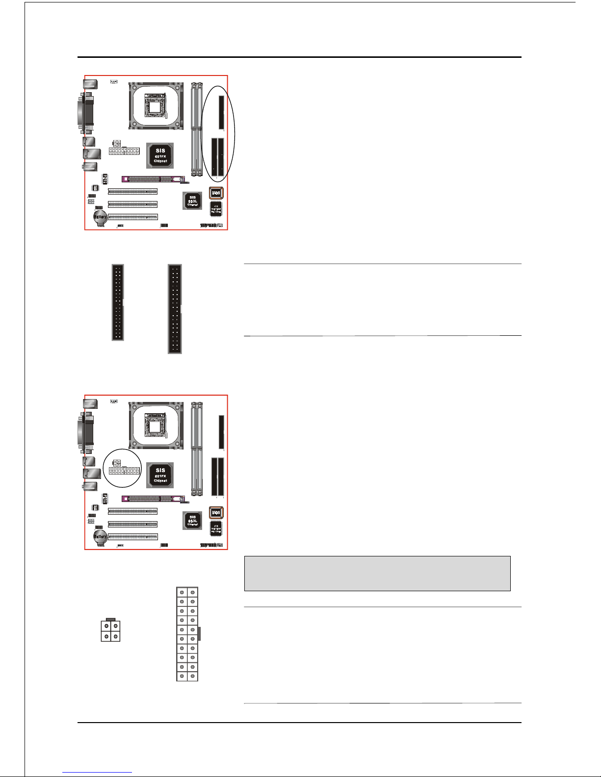
Power-On/Off (Remote)
This board has a 20-pin ATX and a 4-pin ATX12V power supply connector to support
power supplies with Remote On/Off feature. The chassis power button should be
connected to the mainboard front panel PW_ON header (Figure 2).
You can turn off the system in two ways: by pressing the front panel power On/Off
button or using the "Soft Off" function that can be controlled by an operating
system such as Windows®XP/ME/2000/98.
Note: For maintaining the DDR SDRAM power during STR (ACPI S3) function, it is strongly
recommended to use power supplies that have a +5VSB current of (>=) 2A. Please check the
5VSB’s specification printed on the power supply’s outer case.
Note: The board requires a minimum of 250 Watt power supply to operate. Your system configura-
tion (amount of memory, add-in cards, peripherals, etc.) may exceed this minimum power
requirement. To ensure that adequate power, use a 300 Watt (or higher) power supply.
Figure 1: I/O back panel layout
PW-ON
Case (chassis) Power ON/OFF button (PW-ON)
Figure 2: Simple ATX power ON/OFF controller
POWER SUPPLY
12V 4-pin
20-pin
COM1
Parallel Port
VGA1
RJ-45 LAN
(Optional)
USB2.0 ports x 4
PS/2
Mouse
PS/2
Keyboard
Mic-in/Center&Subwoofer (Pink)
Line-out/Front out (Lime)
Line-in/Rear out (Light blue)
Page 8
Introduction
Page 1-4
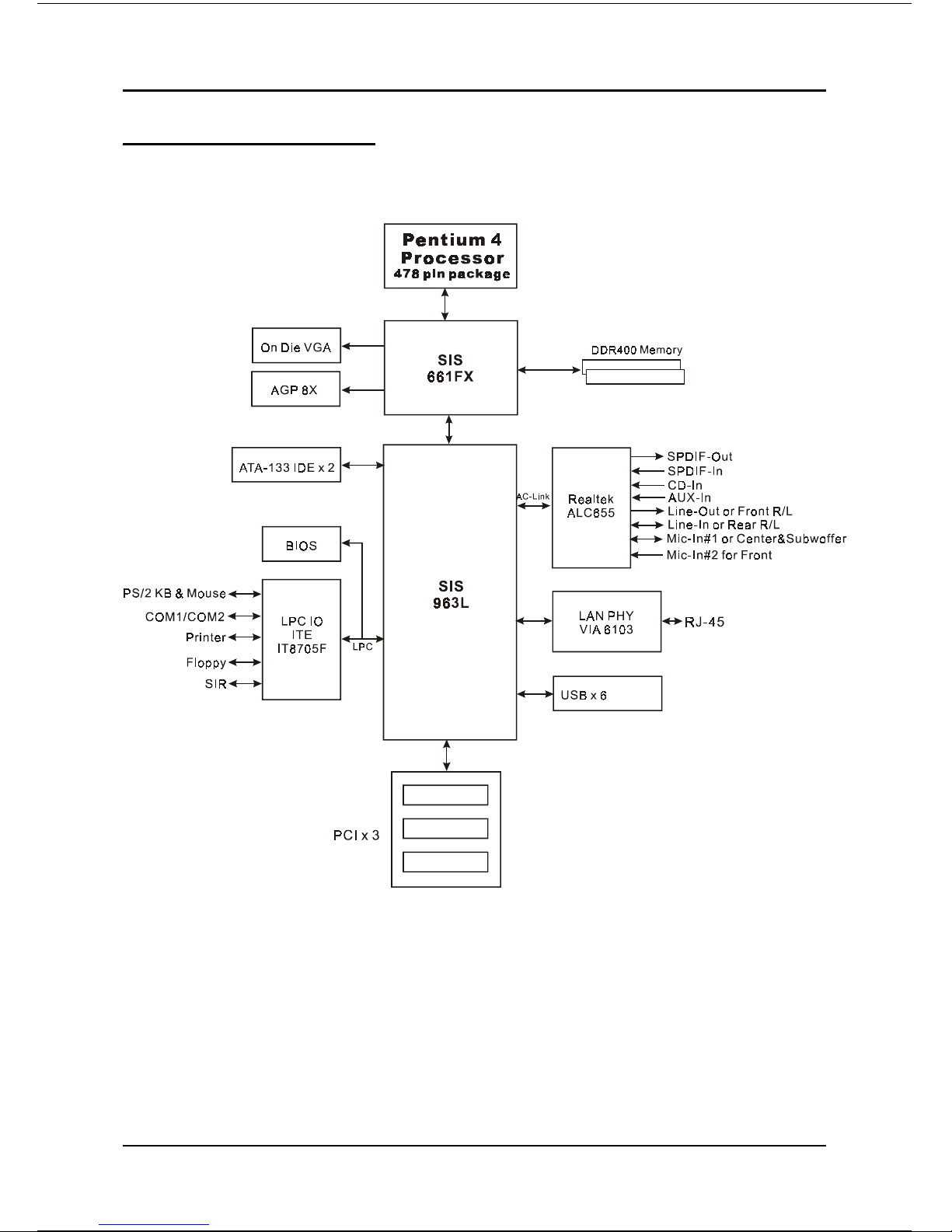
Figure 3: System Block Diagram
System Block Diagram
Page 9

Features
Page 2-1
Section 2
FEATURES
Mainboard Features
Processor
Socket 478 Intel® Pentium® 4 processors up to 3.4+ GHz
Supports Hyper-Threading Technology
To enable the Hyper-Threading Technology function on your computer
system requires ALL of the following platform components:
)CPU: An Intel
®
Pentium® 4 Processor with HT Technology.
)BIOS: A BIOS that supports HT Technology and has it enabled.
)OS: An operating system that supports HT Technology.
Performance will vary depending on the specific hardware and software
you use. See <http://www.intel.com/info/hyperthreading> for information
including details on which processor support HT Technology.
Chipset
SiS 661FX Chipset (661FX + 963L)
- with SiS Mirage Graphics core
Main Memory
Two 184-pin DDR DIMM sockets for PC2100/2700/3200 (DDR266/333/400)
DIMMs
Supports up to 2GB memory size
BIOS
Flash EEPROM with Award BIOS
- ACPI v2.0 compliant
- S3 (Suspend to DRAM) sleep-state support
- SMBIOS (System Management BIOS) v2.2 compliant
- Supports Power failure recovery
- Able to wake the computer from specific states by LAN, Power switch,
PME#, RTC alarm, USB, PS2 K/B, PS2 Mouse, Modem Ring-in COM#1…
Page 10

Features
Page 2-2
Onboard PCI Devices
LAN --> Integrates 10/100Mps Fast Ethernet controller with onboard
VIA 6103 LAN PHY
Legacy IO Controller
ITE IT8705F LPC IO controller with keyboard, mouse, floppy, printer, game,
serial and IR interface
Audio
Six channel audio with analog and digital output using Realtek ALC655
AC’97 CODEC
- AC’97 v2.2 compliant
- In 2-CH mode, supports Line-In (Light Blue), Line-Out (Lime) and Mic-In
(Pink) at rear panel
- In 6-CH mode, supports Rear speaker-out (Light Blue), Front speaker-out
(Lime) and Center&Subwoofer speaker-out (Pink) at rear panel
- Supports CD-In, Aux-In and S/PDIF-in/out interface
- Supports Line-out and Mic-In for front panel
- Supports automatic “jack-sensing”
Peripheral Interfaces
))
))
) At Rear Panel
PS/2 keyboard and mouse ports
One Parallel (printer) port
One Serial port
One VGA port
One RJ45 LAN connector
Four USB2.0 ports
Three Audio jacks
))
))
) Onboard connector and pin-header
One floppy drive connector
Two ATA-133 IDE connectors
Page 11

Features
Page 2-3
Two extra USB2.0 ports
One CD-IN and One AUX-IN connector
One S/PDIF-in/out connector
One Front Panel Audio connector
One IR connector
One COM2 connector
Two Fan connectors
Front Panel Controller
Supports Reset & Soft-Off switches
Supports HDD & Power LEDs
Supports PC speaker
Expansion Slots
One AGP slot supporting 1.5v 4X/8X AGP card
- AGP v3.0 compliant
Three PCI slots with Bus Master support
- PCI v2.2 compliant
Other Features
Magic Health – a H/W monitoring software utility, for voltages, tempera-
tures and fan-speeds sensing
EZ Boot – An easy way let end-user can choose to boot from hard drive,
CD-ROM, floppy, …
KBPO – Keyboard power on, turn on the computer from keyboard
PowerBIOS for excellent Overclocking capabilities through
- subtle frequency tuning on FSB with 1MHz
- Supports complete Asynchronous FSB/Memory and Asynchronous FSB/
PCI scheme for overclocking
Form Factor
245mm x 220 mm Micro ATX size
Page 12

Features
Page 2-4
Page 13
Installation
Page 3-1
Section 3
INSTALLATION
Page 14
Installation
Page 3-2
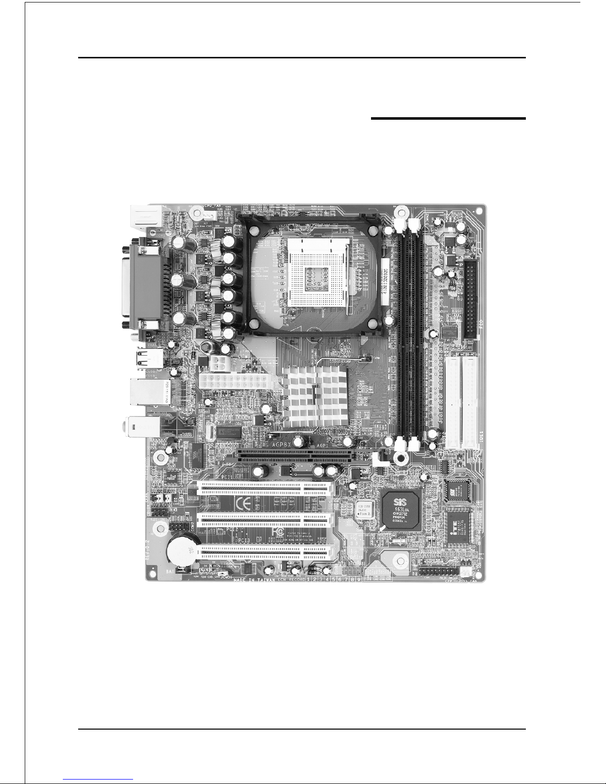
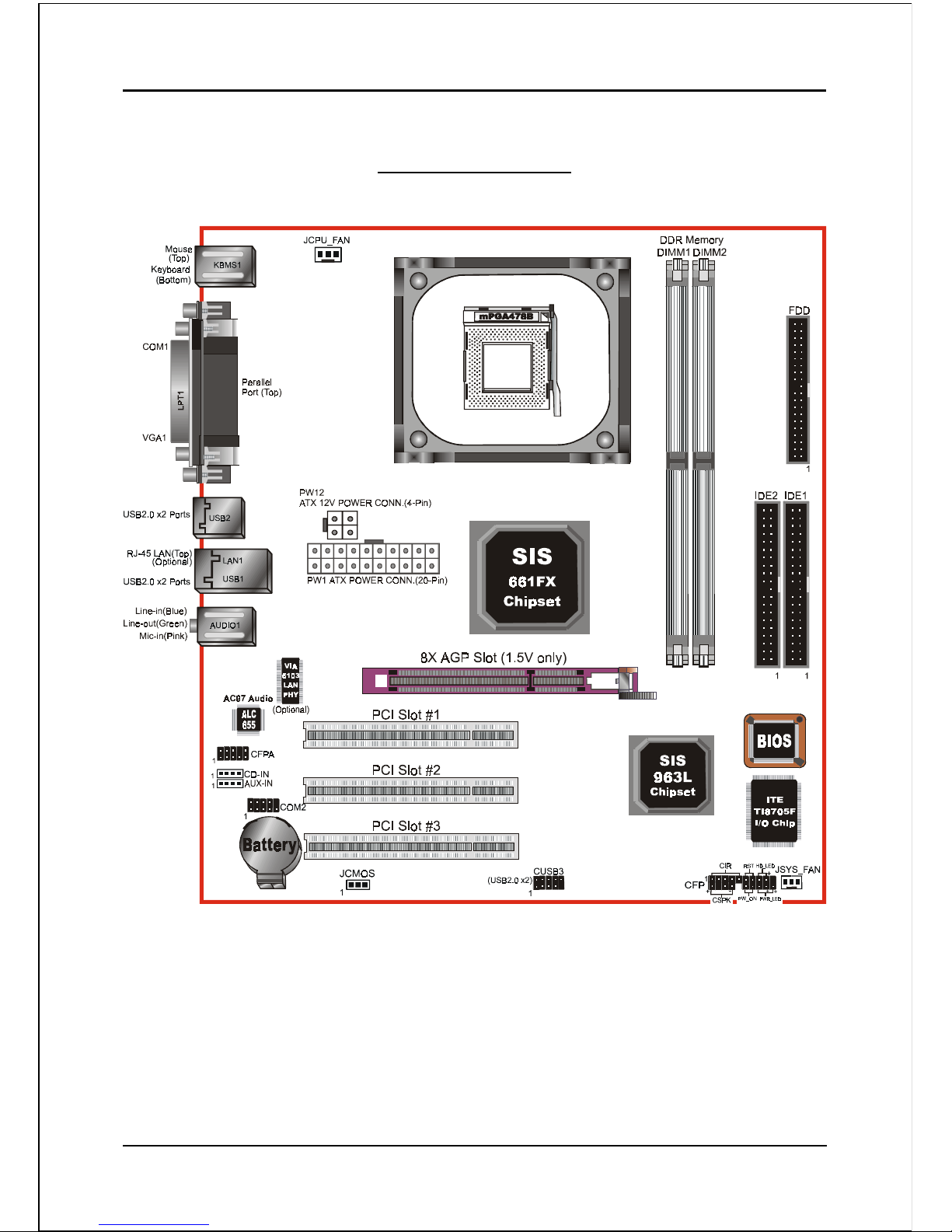
Mainboard Layout
Page 15
Installation
Page 3-3
Easy Installation Procedure
The following must be completed before powering on your new system:
3-1. CPU Installation
3-2. Jumper Settings
3-3. System Memory Configuration
3-4. Expansion Slots
3-5. Device Connectors
3-1 CPU Installation
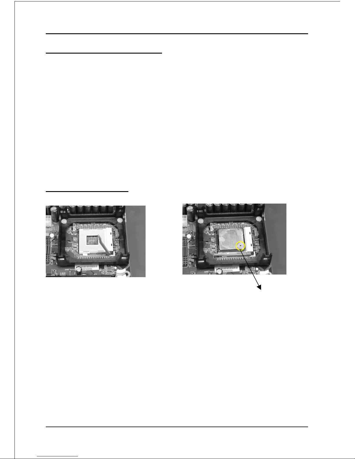
Step 1
Open the socket by raising the actuation
lever.
<Figure 1>
Step 2
Align pin 1 on the CPU with pin 1 on
the CPU socket as shown in the
illustration above. The CPU is keyed to
prevent incorrect insertion. Don’t force
the processor into the socket. If it does
not go in easily, check for mis-orienta-
tion and reinsert the CPU.
Make sure the processor is fully
inserted into the socket.
<Figure 2>
Pin 1
Page 16
Installation
Page 3-4
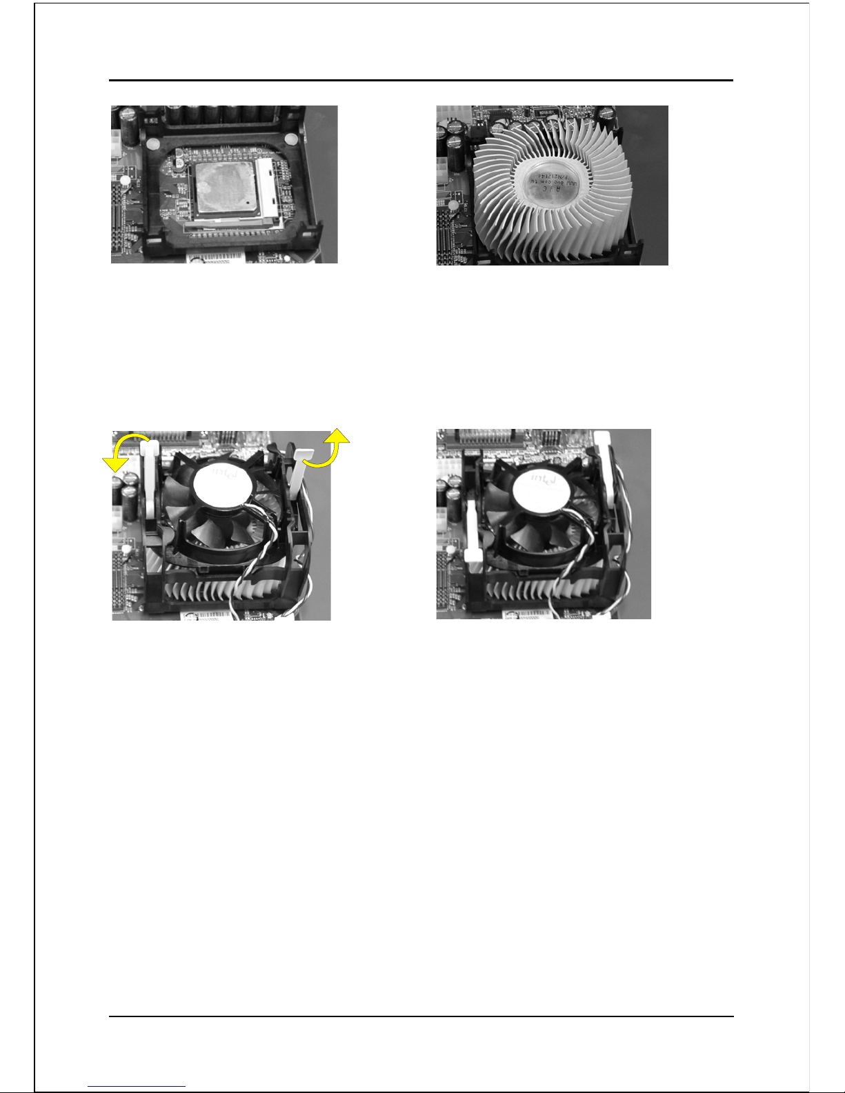
<Figure 3>
Step 4
Apply thermal compound to the top of
the CPU and install the heatsink as
shown.
Step 5
Install the cooling fan assembly. Press
the two clips in the direction of the
arrows shown in Figure 5 to secure the
assembly to the CPU socket.
Step 6
Plug the CPU fan power into the
mainboard’s CPU fan connector.
The installation is complete.
<Figure 4>
<Figure 5> <Figure 6>
NOTES:
• Damage to Intel Pentium
TM
4 processors might result if installed with
incorrect CPU fan and heatsink assemblies. Use Intel’s design thermal
solution shown in the illustrations above: an active heatsink; an extruded
aluminum heatsink base; and a fan attached to the top of the fin array.
• Apply heatsink thermal compound or paste to the CPU to avoid CPU
overheating and damage.
• In accordance with Intel Corp. specifications, do not install a CPU over
50 times to avoid bending the pins and damaging the CPU.
Step 3
Close the socket by lowering and
locking the actuation lever.
Page 17
Installation
Page 3-5
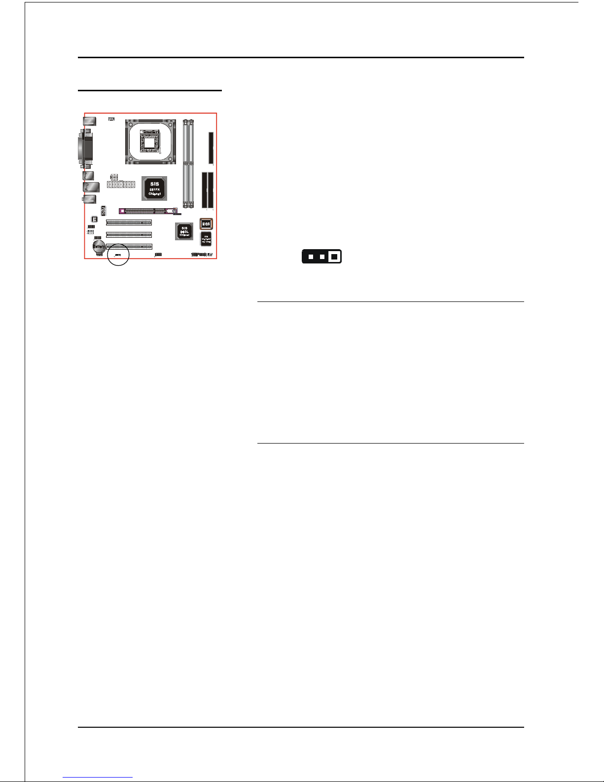
3-2 Jumper Settings
JCMOS:
Settings:
1-2: Normal (Default)
2-3: Clear CMOS
1
Clear CMOS data Jumper
If the CMOS data becomes corrupted or you
forgot the supervisor or user password,
clear the CMOS data to reconfigure the
system back to the default values stored in
the ROM BIOS.
To CMOS Clear data, please follow the steps below.
1. Turn off the system.
2. Change the jumper from “1-2” to “2-3” position
for a few seconds.
3. Replace the jumper on to the “1-2” position.
4. Turn on the system and hold down the <Del>
key to enter BIOS setup.
Page 18

Installation
Page 3-6
3-3 System Memory Configuration
The mainboard accommodates two PC2100/PC2700/PC3200 184-pin DIMMs (Dual In-
line Memory Modules):
• Supports up to 2.0GB of 266/333/400 MHz DDR SDRAM.
• Supports up to 2 DDR DIMMs (refer to Table 1).
• Supports unbuffered non-ECC DIMMs only.
• Supports configurations defined in the JEDEC DDR DIMM specification.
NOTES:
• Using non-compliant memory with higher bus speeds (overclocking)
may severely compromise the integrity of the system.
<Figure 7>
<Table 1>
* DDR SDRAM supports 64, 128, 256, 512MB and 1GB DIMM
modules using 512Mb technology.
yromeMlatoT
1MMIDRDD
)1/0knaB(
2MMIDRDD
)3/2knaB(
BG1=
mumixaM
,BM652,BM821,BM46
1X*BG1,BM215
enoN
BG2=
mumixaM
,BM652,BM821,BM46
1X*BG1,BM215
,BM652,BM821,BM46
1X*BG1,BM215
DIMM1 DIMM2
Page 19
Installation
Page 3-7
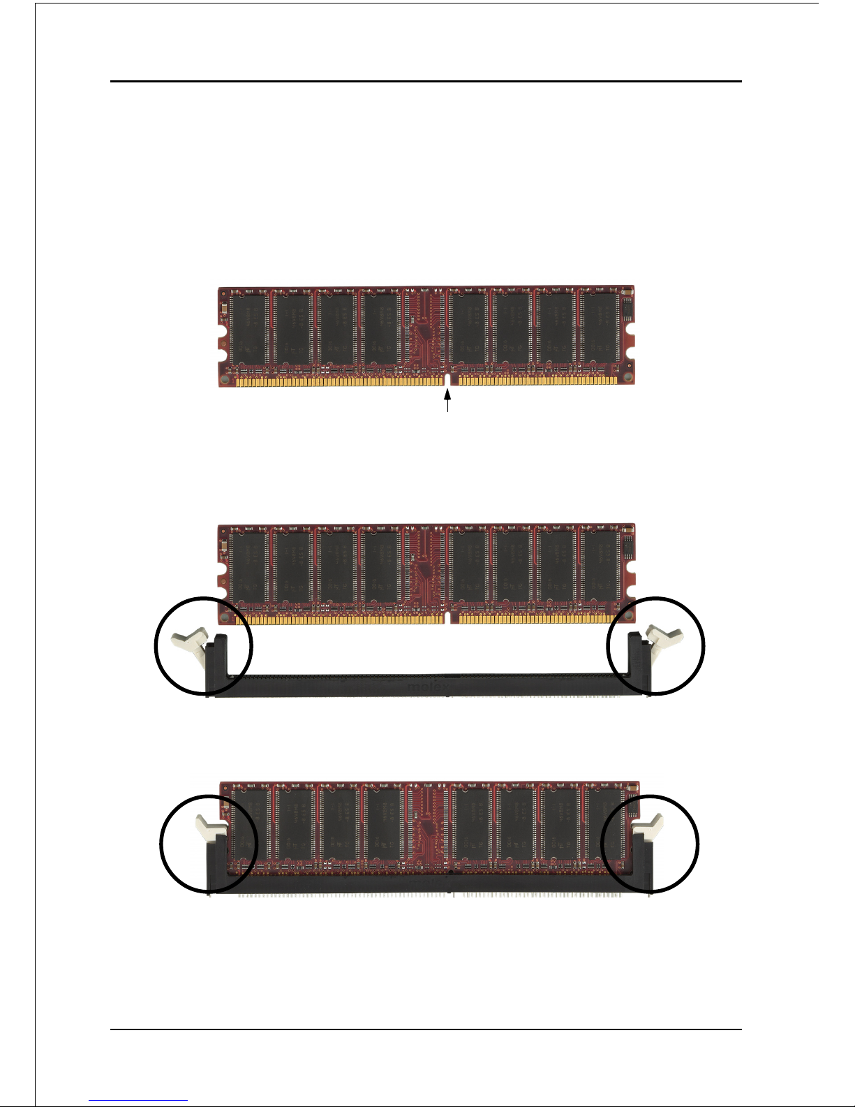
DIMM Module Installation
Figure 8 displays the notch on the DDR DIMM memory module.
DIMMs have 184 pins and one notch that matches with the DDR DIMM socket.
DIMM modules are installed by placing the chip firmly into the socket and
pressing straight down as shown in figure 9 until the white clips close and the
module fits tightly into the DIMM socket (figure 10).
Figure 8 - DIMM notch
Figure 10 - DIMM module clip after installation
To remove the DIMM module press down the white clips and the module will be
ejected from the socket.
Figure 9 - DIMM module clips before installation
CENTER KEY ZONE
(2.5 V DRAM)
Page 20
Installation
Page 3-8
3-4 Expansion Slots
Installing an Expansion Card
The steps below assume that the mainboard is already installed in the system chassis.
1. Make sure the PC and all other peripheral devices connected to its has been
powered down.
2. Disconnect all power cords and cables.
3. Remove the system unit cover.
4. Remove the bracket of the slot that you intend to use. (You need to remove the
screw in order to remove the bracket.)
5. Align the card above the slot then press it down firmly until it is completely
seated in the slot.
6. Secure the card to the chassis with the screw you removed in step 4.
7. Replace the system unit cover.
8. Power on the PC.
9. Enter the BIOS step program to make the necessary settings.
10. Save the settings and restart the PC.
11. Install the software drivers of the expansion cards, if necessary.
AGP Slot
The mainboard is equipped with an AGP
slot. Make sure you install a card that
supports the 1.5V specification.
PCI Slots
The mainboard is equipped with 3 PCI
slots.
PCI Slots
AGP Slot
Page 21
Installation
Page 3-9
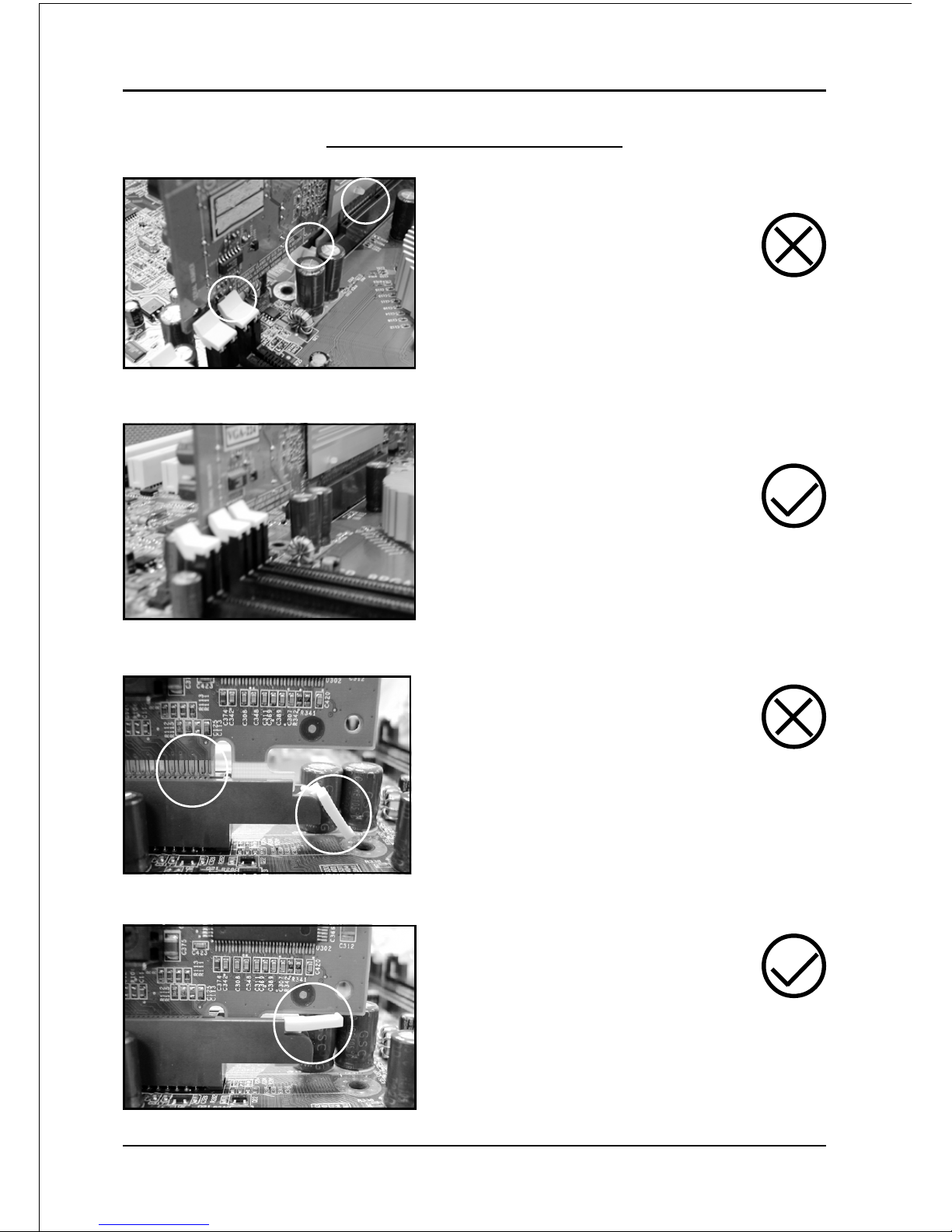
AGP Card Installation Caution
1. AGP card component is blocked
by DIMM socket lock.
2. AGP slot clicker is not locked.
3. AGP card edge connector is not
inserted properly.
1. AGP card component is not
blocked by DIMM socket lock.
2. AGP slot clicker is locked.
3. AGP card edge connector is
inserted properly.
1. AGP slot clicker is not locked.
2. AGP card edge connector is not
inserted properly.
1. AGP slot clicker is locked.
2. AGP card edge connector is
inserted properly.
Page 22
Installation
Page 3-10
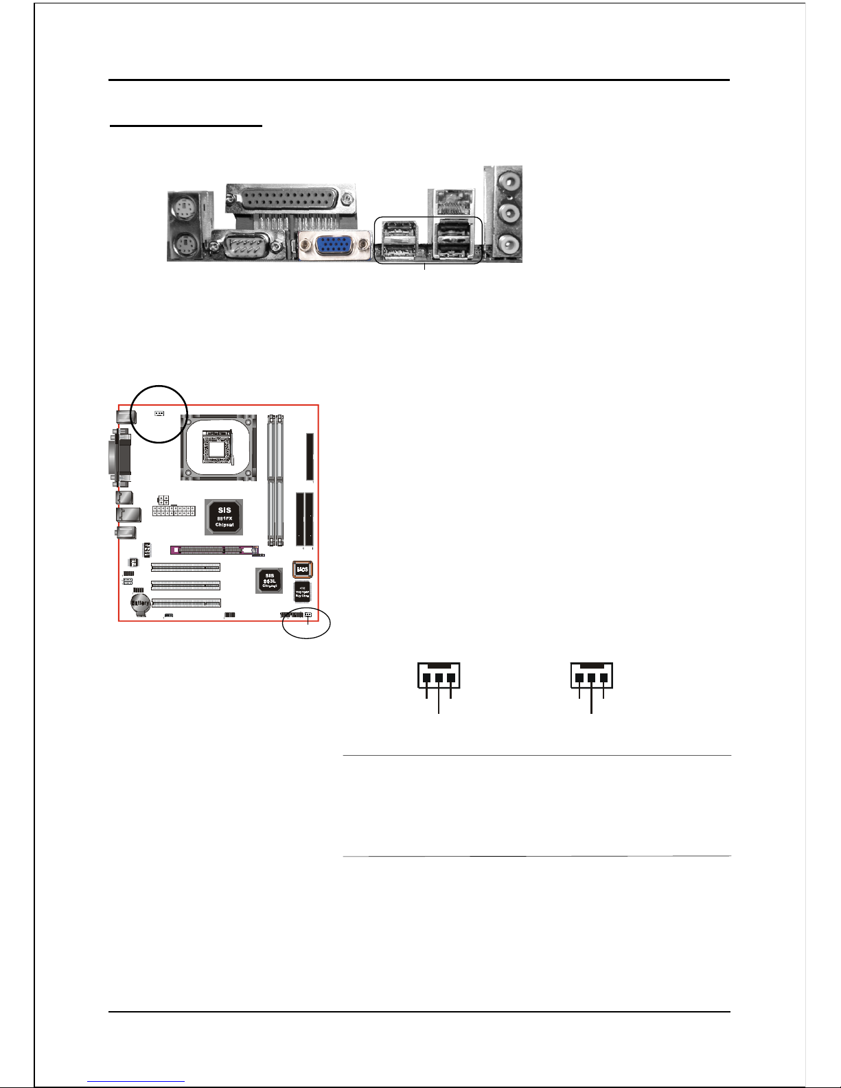
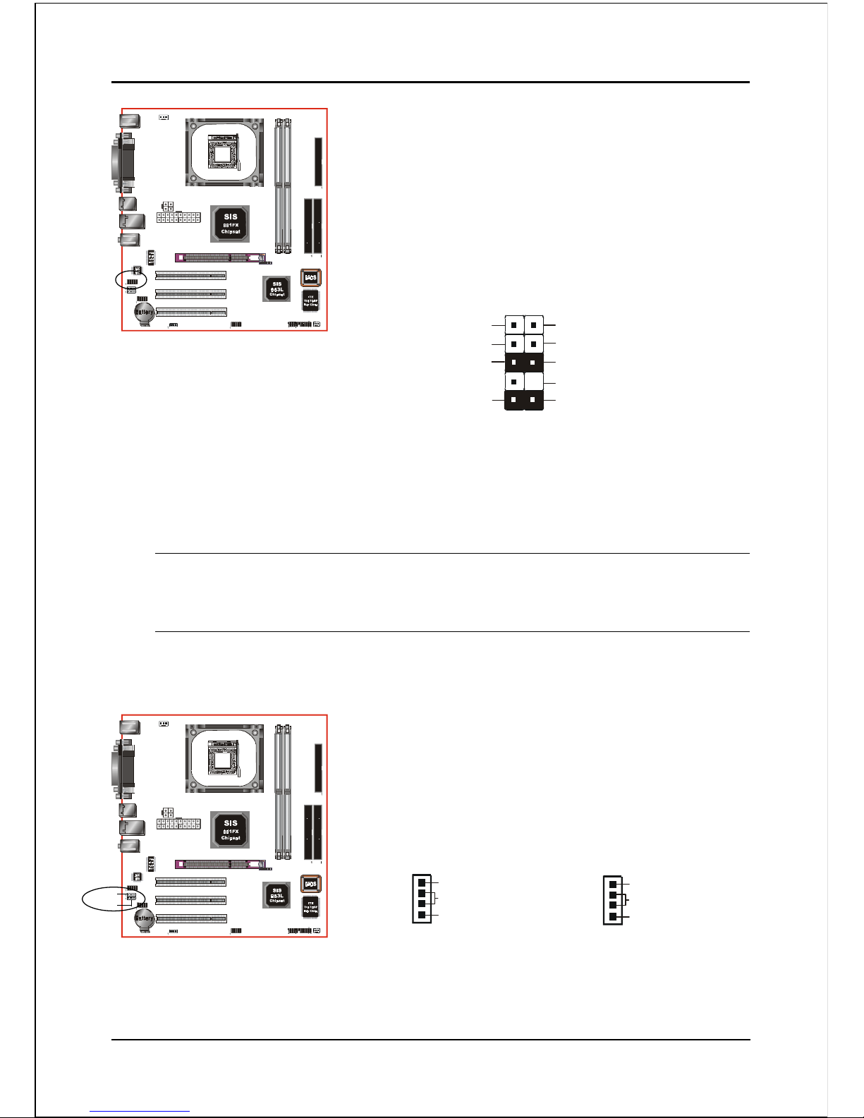
JCPU_FAN / JSYS_FAN:
CPU/Chassis Fan Power Connectors
JCPU_FAN: The CPU must be kept cool by using a
heatsink with fan assembly.
JSYS_FAN: The chassis fan will provide adequate
airflow throughout the chassis to
prevent overheating the CPU.
Ground
+12V
Sense
JCPU_FAN
Figure 11 - I/O Ports
JCPU_FAN
JSYS_FAN
JSYS_FAN
3-5 Connectors
COM1
Parallel Port
VGA1
RJ-45 LAN
(Optional)
USB2.0 ports x 4
PS/2
Mouse
PS/2
Keyboard
Mic-in/Center&Subwoofer (Pink)
Line-out/Front out (Lime)
Line-in/Rear out (Light blue)
Ground
+12V
Sense
The system is capable of monitoring the fan speed in
RPM (Revolutions Per Minute). Refer to the PC
Health Status submenu of the BIOS for the current
speed of the CPU fan , power fan and chassis fan.
Page 23
Installation
Page 3-11
PW1
PW12
PW1: 20-pin ATX Power Connector
PW12: 4-pin ATX12V Power Connector
The mainboard is equipped with a standard 20-pin
ATX main power connector and a 4-pin +12V
power connector for connecting an ATX12V
power supply. The plugs of the power cables are
designed to fit in only one orientation. Insert the
plugs into the connectors until they fit in place.
Caution:
The PW1 and PW12 Power Connector must be used simultaneously
or else this system will not boot-up.
40 39
2
1
IDE1/IDE2
34 33
2
1
FDD
The board requires a minimum of 250 Watt power
supply to operate. Your system configuration (amount
of memory, add-in cards, peripherals, etc.) may
exceed this minimum power requirement. To ensure
that adequate power, use a 300 Watt or greater power
supply.
1
3
1
-12V3.3V
Ground+5V
PS-ON+5V
-5VPW-OK
+5V5VSB
+5V+12V
+12V+12V
10
11
4
2
3.3V3.3V
GroundGround
GroundGround
GroundGrou nd
GroundGround
20
PW1
PW12
IDE1IDE2
FDD
FDD: Floppy Controller Connector
This mainboard connects floppy disk drive.
IDE1/IDE2: Ultra DMA-66/100/133 Primary/Secondary
IDE Connector
This mainboard is equipped with 2 IDE connectors
to support up to 4 ATA-100 IDE drives.
It supports PIO and DMA mode operations for
maximum data transfer rate of 133MB/sec per channel.
When using two IDE drives, one must be set to Mas-
ter mode and the other to Slave mode. Refer to your
disk drive user’s manual for information about selecting the proper drive switch settings.
Page 24
Installation
Page 3-12
Settings:
Pins (5-6) & (9-10) Short (default): Only the onboard rear
panel audio jack can be used.
Pins (5-6) & (9-10) Open: Only front panel audio jack can
be used.
CFPA: Front Panel Audio Connector
When the jumpers are removed this connector can
be used for front panel audio. The front panel
phone jack should have “normal close” switch.
Without phone plug inserted, the rear panel audio is
enabled. With phone plug inserted, the rear panel
audio will be disabled.
In 2-Channel audio mode, Mic-In is shared for both front panel and rear panel.
In 6-Channel audio mode, the Mic-In is dedicated for front panel use, and rear
panel Mic-In function will switch to Center and Subwoofer support.
1
Rear Line-out-FR
Front Line-out-R
Rear Line-out-FL
Front Line-out-L
MIC_In
NC
+5V
Key
9
2
10
GND
CD-IN
AUX-IN
CD-IN/AUX-IN: CD Audio_IN Connector
The CD-IN and AUX-IN connectors are used to
receive audio form a CD-ROM drive, TV tuner or
MPEG card.
CD_IN_Left
1
CD_IN_Right
CD_Reference
AUX_IN_Left
1
AUX_IN_Right
GND
CD-IN AUX-IN
Page 25

Installation
Page 3-13
COM2: Serial Port Connector
The serial port can be used with modems, serial
printers, remote display terminals, and other serial
device.
1
9
2
10
CTS
Ground
TXD
RI
RTS
RXD
DTR
DCD
DSR
1
VCC
NC
GND
Key
GND
Data0-
Data1-
VCC
Data0+
Data1+
9
2
10
CUSB3: Two USB 2.0 ports
USB2.0 allows data transfer speed up to 480Mbps.
This mainboard includes 2 additional USB2.0 ports,
identified by two 10-pin connector.
If you wish to use the additional USB ports, install
the card-edge bracket to the system chassis then
insert its cables to this 10-pin connector.
CAUTION !
Please make sure the USB cable has the same pin
assignment. A different pin assignment may cause
damage to the system.
If you need the USB cable, please contact our retailer.
Page 26

Installation
Page 3-14
CFP
CFP: Front Panel Connector
HD_LED
This LED will light up whenever the hard drive
is being accessed.
PWR_LED
This connects to the power button of the
system chassis
RST
This switch allows you to reboot without
having to power off the system thus prolonging
the life of the power supply or system.
PW_ON
This is connected to the power button on the
case. To use the Soft-Off by PWR-BTTN
feature, refer to the Power Management Setup
in the BIOS setup section of this manual.
CIR: IR connector
Connect the IrDA cable (if available) to this IR
connector.
CSPK: Speaker
Connect to the system’s speaker for beeping
CIR
CSPK
Page 27

Installation
Page 3-15
3-6 External Modem Ring-in Power ON and
Keyboard Power ON Functions (KBPO)
Modem-Ring Power ON Function
The I/O chipset provides the two serial ports with the External Modem Ring-in Power
ON function. Once you connect an external modem to COM1 or COM2, the
mainboard enables you to turn on the system through remote and host dial-up
control.
Keyboard Power ON Function
The mainboard features a keyboard power on function that enables you to turn on
the power supply using a keypress. Refer to the Power Management Setup in the
BIOS setup section for details. To enable this feature, the BIOS default setting is
“Any Key”. To power off the system, use the Soft-OFF function under Windows
XP/ME/2000/98. (refer to Windows online help).
NOTES:
• We recommend you use a power supply with 2.0 A in 5.0 VSB, which
supports PCI 2.2 specification for remote power-on and wake-up functions.
Page 28

Installation
Page 3-16
3-7 ACPI S3 (Suspend To RAM) Function
This mainboard supports the STR (Suspend To RAM) power management
scheme by maintaining the appropriate power states in the DDR SDRAM
interface signals. The power source to the DDR SDRAM is kept active during
STR (ACPI S3). Advanced Configuration Power Interface (ACPI) provides many
Energy Saving Features for operating systems that support Instant ON and
QuickStartTM function.
1. To enable STR functionality to save system power :
a. Install ACPI certified add-on cards (such as AGP, LAN, and modem cards).
b. In BIOS, under Power Management Setup (refer to Section 4), select “ACPI
Suspend Type: S3(STR)”. If you have a USB mouse or keyboard, set “USB
Port Wake Up Control” to “Enabled”.
c. Install Windows® XP/2000/ME/98SE.
d. Restart the system.
e. When in Windows, open the Control Panel Power Management application,
and click the Advanced tab. In the Power buttons section, select “Stand By”
from the drop-down lists.
2. To activate the STR function:
a. Click the START button and choose Shut Down.
b. In the Shut Down Windows dialog box, select the Stand By option to enter
STR mode.
The following are the differences between STR power saving mode and Sus-
pend (Power On Suspend) mode:
a. STR is the most advanced Power Management mode.
b. STR cuts all the power supplied to peripherals except to memory - max. power
saving.
c. STR saves and keeps all on-screen data including any executed applications
to DDR SDRAM.
d. In STR mode, you must push the power button (connected to the onboard PW-
On of CFP pin), click your USB mouse buttons, or press your USB keyboard
keys to wake up your system to the last display.
Page 29

BIOS
Page 4-1
Section 4
BIOS SETUP
Main Menu
The ROM BIOS contains a built-in Setup program which allows user to modify the
basic system configuration and hardware parameters. The modified data is stored in
a battery-backed CMOS, so that data will be retained even when the power is turned
off. In general, the information saved in the CMOS RAM will stay unchanged unless
there is a configuration change in the system, such as hard drive replacement or a
device is added.
It is possible for the CMOS battery to fail causing CMOS data loss. If this happens
you will need install a new CMOS battery and reconfigure your BIOS settings.
To enter the Setup Program :
Power on the computer and press the <Del> key during the POST (Power On Self
Test). The BIOS CMOS SETUP UTILITY opens. (Figure 1)
Figure 1: CMOS Setup Utility
The BIOS setup screen and description are for reference only, and may
not exactly match what you see on your screen. The contents of BIOS are
subject to change without notice. Please visit our website for updates.
Page 30

BIOS
Page 4-2
The main menu displays all the major selection items. Select the item you need to
reconfigure. The selection is made by moving the cursor (press any direction (arrow
key ) to the item and pressing the ‘Enter’ key. An on-line help message is displayed
at the bottom of the screen as the cursor is moved to various items which provides a
better understanding of each function. When a selection is made, the menu of the
selected item will appear so that the user can modify associated configuration
parameters.
4-1 Standard CMOS Setup
Choose “STANDARD CMOS FEATURES” in the CMOS SETUP UTILITY Menu
(Figure 2). Standard CMOS Features Setup allows the user to configure system
settings such as the current date and time, type of hard disk drive installed, floppy
drive type, and display type. Memory size is auto-detected by the BIOS and
displayed for your reference. When a field is highlighted (use direction keys to move
the cursor and the <Enter> key to select), the entries in the field can be changed by
pressing the <PgDn> or the <PgUp> key.
Figure 2: Standard CMOS Setup
Notes:
• If the hard disk Primary Master/Slave and Secondary Master/Slave are set to Auto, the hard
disk size and model will be auto-detected.
• The “Halt On:” field is used to determine when the BIOS will halt the system if an error
occurs.
Page 31

BIOS
Page 4-3
4-2 Advanced BIOS Features
Selecting the “ADVANCED BIOS FEATURES” option in the CMOS SETUP UTILITY
menu allows users to change system related parameters in the displayed menu. This
menu shows all of the manufacturer’s default values for the board.
Pressing the [F1] key displays a help message for the selected item.
Figure 3: BIOS Features Setup
CPU Feature
This field is available only for Pentium® CPU with Prescott core.
CPU L1 & L2 Cache
This controls the status of the processor’s internal Level One and Level Two cache.
Options: Enables, Disabled.
CPU L3
This controls the status of the processor’s internal Level Three cache.
Options: Enables, Disabled.
Hyper-Threading Technology
Enables the CPU Hyper-Threading Technology.
Options: Enables, Disabled.
Page 32

BIOS
Page 4-4
Note: It is recommend to enable Hyper-Threading Technology on system with
Windows XP and Linux 2.4 and disabling it for legacy OS.
CPU L2 Cache ECC Checking
This item allows you to enable/disable CPU L2 Cache ECC checking.
Options: Enables, Disabled.
Quick Power On Self Test
This category speeds up the Power On Self Test (POST). This setting will shorten or
skip some items checked during POST.
Options: Enables, Disabled.
First /Second/Third/Other Boot Device
The BIOS attempts to load the operating system from the devices in the sequence
selected in these items.
Options: Floppy, LS120, HDD-0, SCSI, CDROM, HDD-1, HDD-2, HDD-3, ZIP100,
LAN, Disabled.
Boot Other Device
When enabled, the system searches all other possible locations for an operating
system if it fails to find one in the devices specified under the first, second, and third
boot devices.
Options: Enabled, Disabled.
Boot Up Floppy Seek
If this item is enabled, it checks the size of the floppy disk drives at start-up time.
You don’t need to enable this item unless you have a legacy diskette drive with
360K capacity.
Options: Enabled, Disabled.
Boot Up NumLock Status
This controls the state of the NumLock key when the system boots. The default is On.
On: The keypad acts as a 10-key pad.
Off: The keypad acts like cursor keys.
Gate A20 Option
This refers to the way the system addresses memory above 1 MB (extended memory).
Options: Fast, Normal.
Page 33

BIOS
Page 4-5
Typematic Rate Setting
This determines the keystrokes repeat rate. The default is Disabled.
Enabled: Allows typematic rate and typematic delay programming.
Disabled: The typematic rate and typematic delay will be controlled by the keyboard
controller in your system.
Typematic Rate (Chars/Sec)
This is the number of characters that will be repeated by a keyboard press.
Options: 6 ~ 30 characters per second.
Typematic Delay (msec)
This setting controls the time between the first and the second character displayed
by typematic auto-repeat.
Options: 250/500/750/1000 msec.
Security Option
This category allows you to limit access to the System and Setup, or just to Setup.
The default is Setup.
System: The system will not boot and access to Setup will be denied unless the
correct password is entered at the prompt.
Setup: The system will boot, but access to Setup will be denied unless the
correct password is entered at the prompt.
APIC Mode
This item allows you to enable APIC (Advanced Programmable Interrupt Controller)
functionality. APIC is an chip that provides symmetric multiprocessing (SMP) for its
Pentium systems.
Options: Enabled, Disabled.
MPS Version Control For OS
Specifies the Multiprocessor Specification (MPS). Version 1.4 supports multiple PCI
bus configurations by incorporating extended bus definitions. Enable this for
Windows NT or Linux. For older operating systems, select Version 1.1.
Options: 1.1, 1.4.
OS Select For DRAM > 64 MB
Some operating systems require special handling. Use this option only if your
system has greater than 64 MB of memory.
Options: OS2, Non-OS2.
Page 34

BIOS
Page 4-6
HDD S.M.A.R.T. Capability
The S.M.A.R.T. (Self-Monitoring, Analysis, and Reporting Technology) system is a
diagnostics technology that monitors and predicts device performance. S.M.A.R.T.
Software resides on both the disk drive and the host computer. If a device failure is
predicted, the host software, through the Client WORKS S.M.A.R.T applet, warns the
user of the impending condition and advises appropriate action to protect the data.
Options: Enabled, Disabled.
Video BIOS Shadow
This option allows video BIOS to be copied into RAM. Video Shadowing will increase
the video performance of your system.
Options: Enabled, Disabled.
4-3 Advanced Chipset Features
Choose the “ADVANCED CHIPSET FEATURES” option in the CMOS SETUP
UTILITY menu to display following menu.
Figure 4: Chipset Features Setup
System BIOS Cacheable
This item allows the system BIOS to be cached in memory for faster execution.
Options: Disabled, Enabled.
Page 35

BIOS
Page 4-7
Video RAM Cacheable
This item allows the video RAM to be cached in memory for faster execution.
Options: Disabled, Enabled.
DRAM Clock / Timing Control
Scroll to DRAM Clock/Timing Control and press <Enter>. The following screen appears:
Performance Mode
This item will enhance the memory performance. We recommend you leave
“Disabled” at the default value. Selecting “Enabled” may cause instability.
Options: Disabled, Enabled.
DRAM Timing Control
For setting DRAM Timing, select By SPD to follow PC DDR SDRAM Serial
Presence Detect Specification.
Options: Manual, By SPD.
DRAM CAS Latency
This item specifies the number of clock cycles needed after a Column Address Strobe
(CAS) signal before data can be read.
Options: 2T, 2.5T, 3T.
RAS Active time (tRAS)
This item specifies the number of clock cycles needed after a bank active command
before a precharge can occur (sets the minimum RAS pulse width.).
Options: 6T ~ 9T.
RAS precharge Time (tRP)
This item refers to the number of cycles required to return data to its original
location to close the bank or the number of cycles required to page memory before
the next bank activate command can be issued.
Options: 2T ~ 5T.
Page 36

BIOS
Page 4-8
RAS to CAS Delay (tRCD)
This item sets the delay in clock cycles between RAS (Row Address Strobe) and
CAS (Column Address Strobe) .
Options: 2T ~ 5T.
AGP&P2P Bridge Control
Scroll to AGP&P2P Bridge Control and press <Enter>. The following screen appears:
AGP Aperture Size (MB)
This item defines the size of the aperture if you use an AGP graphics adapter. It
refers to a section of the PCI memory address range used for graphics memory.
Options: 32, 64, 128, 256, 512 MB.
Graphic Window WR Combin
To program P6 class CPU video RAM cache write-combination mode to enhance
3D video performance.
Options: Enabled, Disabled.
AGP Fast Write Support
This item allows you to use Fast Write transfer for CPU write to graphics adapter’s
memory.
Options: Enabled, Disabled.
AGP Data Rate
This item allows you to select the AGP Date Rate.
Options: Auto, 1x, 2x, 4x, 8x.
Onchip AGP Control
Scroll to Onchip AGP Control and press <Enter>. The following screen appears:
Page 37

BIOS
Page 4-9
VGA Share Memory Size
This item allows you to select the VGA share memory size for video.
Options: 16MB, 32MB, 64MB, 128MB.
Graphics Engin Clock
This item allows you to select the Graphics Engine Clock.
Options: 133MHz, 166MHz, 200MHz.
4-4 Integrated Peripherals
Figure 5: Integrated Peripherals
IDE HDD Block Mode
IDE Block Mode allows the controller to access blocks of sectors rather than a
single sector at a time. The default is Enabled.
Options: Enabled, Disabled.
Onboard Lan Boot ROM
Enable/disable the onboard LAN boot ROM. The default is Disabled.
Options: Enabled, Disabled.
Init Display First
This item is used to select whether to initialize the AGP or PCI first when the system
boots.
Options: PCI Slot, AGP.
Page 38

BIOS
Page 4-10
IDECH0 / IDECH1 Access Interface
IDE Access Interface Selection.
Options: EDB Bus, PCI Bus.
USB0 / USB1 / USB2 / USB2.0 Access Interface
USB Access Interface Selection.
Options: EDB Bus, PCI Bus.
MAC Access Interface
MAC Access Interface Selection.
Options: EDB Bus, PCI Bus.
Audio Access Interface
Audio Access Interface Selection.
Options: EDB Bus, PCI Bus.
SIS OnChip IDE Device
Scroll to SIS OnChip IDE Device and press <Enter>. The following screen appears:
Internal PCI/IDE
The mainboard supports two channel of ordinary IDE interface. Select “Both” to
activate each channel separately.
Options: Primary, Secondary, Both, Disabled.
Note: If you do not use the onboard IDE connector, then you will need to set the
Onboard Primary PCI IDE and Onboard Secondary PCI IDE to “Disabled”.
IDE Primary/Secondary Master/Slave PIO
The four IDE PIO (Programmed Input/Output) fields let you set a PIO mode (0-4)
for each of the four IDE devices that the onboard IDE interface supports. Modes 0
Page 39

BIOS
Page 4-11
to 4 provide successively increased performance. In Auto mode, the system
automatically determines the best mode for each device.
Options: Auto, Mode 0 ~ 4.
Primary/Secondary Master/Slave UDMA
Select the mode of operation for the IDE drive. Ultra DMA-100/133 implementa-
tion is possible only if your IDE hard drive supports it and the operating environ-
ment includes a DMA driver. If your hard drive and your system software both
support Ultra DMA-100/133, select Auto to enable UDMA mode by BIOS.
Options: Auto, Disabled.
IDE DMA transfer access
Automatic data transfer between system memory and IDE device with minimum CPU
intervention. This improves data throughput and frees CPU to perform other tasks.
Options: Enabled, Disabled.
IDE Burst Mode
Selecting Enabled reduces latency between each drive read/write cycle, but may
cause instability in IDE subsystems that cannot support such fast performance. If
you are getting disk drive errors, try setting this value to Disabled. This field does
not appear when the Internal PCI/IDE field, above, is Disabled.
Options: Enabled, Disabled.
Onboard Device
Scroll to Onboard Device and press <Enter>. The following screen appears:
SIS USB Controller
Enables the USB controller.
Options: Enabled, Disabled.
Page 40

BIOS
Page 4-12
USB Ports Number
Selects the USB Ports number.
Options: 3 Ports, 4 Ports, 5 Ports, 6 Ports .
USB 2.0 Support
Enables the USB2.0 Support.
Options: Enabled, Disabled.
USB Keyboard Support
Enable/Disable support for USB keyboard under DOS.
Options: Enabled, Disabled.
USB Mouse Support
Enable/Disable support for USB mouse under DOS.
Options: Enabled, Disabled.
SIS AC97 Audio
This item allows you disable the chipset on-chip AC97 Audio.
Options: Enabled, Disabled.
SIS 10/100M ETHERNET
Enables the onboard LAN feature.
Options: Enabled, Disabled.
SIS MAC Address Input
Allows you to input the MAC (SIS) address.
Onboard Super IO Device
Scroll to Onboard Super IO Device and press <Enter>. The following screen appears:
Onboard FDC Controller
Select “Enabled” if you wish to use onboard floppy disk controller (FDC). If you
install an external FDC or the system has no floppy drive, select “Disabled “in this field.
Options: Enabled, Disabled.
Page 41

BIOS
Page 4-13
Onboard Serial Port 1/2
Select an address and corresponding interrupt for the first and second serial ports.
Options: 3F8/IRQ4, 2E8/IRQ3, 3E8/IRQ4, 2F8/IRQ3, Disabled, Auto.
UART Mode Select
This field configures the onboard CIR pin header for IR application. Select the
required IR protocol or select “Normal” to disable IR mode.
Options: Normal, IrDA and ASKIR.
UR2 Duplex Mode
This item allows you to select IR half/full duplex function.
Options: Half, Full.
Onboard Parallel Port
This field allows the user to configure the LPT port.
Options: 378/IRQ7, 278/IRQ5, 3BC/IRQ7, Disabled.
Parallel Port Mode
This field allows the user to select the parallel port mode.
Options: SPP, EPP, ECP, ECP+EPP.
ECP Mode USE DMA
This field allows the user to select DMA1 or DMA3 for the ECP mode.
Options: DMA1, DMA3.
Page 42

BIOS
Page 4-14
4-5 Power Management Setup
Choose the “POWER MANAGEMENT SETUP” in the CMOS SETUP UTILITY to
display the following screen. This menu allows the user to modify the power
management parameters and IRQ signals. In general, these parameters should not be
changed unless it’s absolutely necessary.
Figure 6: Power Management
ACPI Function
Enables the ACPI Function.
Options: Enabled, Disabled.
ACPI Suspend Type
This item allows you to select S1(Power-On-Suspend) or S3(Suspend-To-RAM)
function.
Options: S1(POS), S3(STR), S1&S3.
Power Management
Use this to select your Power Management selection. The default is User define.
Max. saving: Maximum power savings. Inactivity period is 1 minute in each mode.
Min. saving: Minimum power savings. Inactivity period is 1 hour in each mode.
User define: Allows user to define PM Timers parameters to control power saving
mode.
Page 43

BIOS
Page 4-15
Suspend Mode
Automatically, shuts off all devices except the CPU after a preset period of system
inactivity.
Options: Disabled, 1 , 2, 4 ,6, 8, 10, 20, 30, 40 min and 1 hour .
Video Off Option
When enabled, this feature allows the VGA adapter to operate in a power saving mode.
Always On: Monitor will remain on during power saving modes.
Suspend-->Off: Monitor blanked when the systems enters the Suspend mode.
Susp,Stby-->Off: Monitor blanked when the systems enters either Suspend or
Stanby mode.
All Modes-->Off: Monitor blanked when the systems enters any power saving mode.
Video Off Method
This option allows you to select how the video will be disabled by the power
management. The default is V/H Sync + Blank
V/H Sync + Blank: System turns off vertical and horizontal synchronization ports
and writes blanks to the video buffer.
DPMS Support: Select this option if your monitor supports the Display Power
Management Signaling (DPMS) standard of the Video Electronics
Standards Association (VESA). Use the software supplied by
your video subsystem to select video power management values.
Blank Screen: System only writes blanks to the video buffer.
HDD Off After
This selects the hard disk drive be turned off after a selected number of minutes or
when the rest of the system goes into a Suspend mode.
Options: Disabled, 1Min ~ 15Min.
Power Button Override
Use this to select your soft-off function. The default is Instant Off.
Instant Off: Turns off the system instantly.
Delay 4 Second : Turns off the system after a 4 second delay. If momentary press
of button, the system will go into Suspend Mode. To wake the
system, press the power button again.
Page 44

BIOS
Page 4-16
PwerOn After Pwr-Fail
This item enables your computer to automatically restart or return to its last operat-
ing status after power returns from a power failure.
Off: The system stays off after a power failure.
Former-Sts: The system returns to the state it was in just prior to the power
failure.
Delay Prior to Thermal
Set this item to enable the CPU Thermal protection feature to engage after the
specified time. Recommended to set to the lowest value (minutes) that exceeds the
time it takes to fully boot up your computer.
Options: None, 1, 2, 4, 8, 16, 32, 64 minutes.
PM Wake Up Events
Scroll to PM Wake Up Events and press <Enter>. The following screen appears:
IRQ [3-7,9-15], NMI
Allows you to set system to monitor IRQ[3-7,9-15], NMI for activity to awaken
system form a power management mode.
Options: Enabled, Disabled.
IRQ 8 Break Suspend
Options: Enabled, Disabled.
RING Power Up Control
This option is used to set the remote ring in features.
Options: Enabled, Disabled.
MACPME Power Up Control
This option is used to set the Wake-On-LAN feature.
Options: Enabled, Disabled.
Page 45

BIOS
Page 4-17
PCIPME Power Up Control
An input signal from PME on the PCI card awakens the system from a soft off state.
Options: Enabled, Disabled.
USB Port Wake Up Control
When enabled, any USB Keyboard or mouse activity awakens the system from S3
mode.
Options: Enabled, Disabled.
PS2KB Wake up from S3/S4/S5
This item allows you to select Any Key, Hot Key or Password to wake-up the
system by PS2 Keyboard from S3/S4/S5. When select Password, please press
<Enter> key to change password max 8 numbers. If select Password and press
<Enter> key twice, it mean Keyboard Power On function disabled.
Note: Hot key is Ctrl + Alt + Backspace
PS2MS Wakeup from S3/S4/S5
This item allows you to use PS/2 Mouse to wake up the system from S3/S4/S5.
Options: Disabled, Click, Move & Click.
Power Up by Alarm
When enabled, you can set the month , date and time in the following three fields.
Any event occurring at the specified date or time awakens the system from power
savings mode.
Options: Disabled, Enabled.
Page 46

BIOS
Page 4-18
4-6 PNP/PCI Configuration
This page lets the user to modify the PCI IRQ signals when various PCI cards are
inserted.
WARNING: Conflicting IRQ’s may cause system unable to locate certain devices.
Figure 7: PNP/PCI Configuration Setup
Reset Configuration Data
This setting allows you to clear ESCD data.
Disabled: Normal Setting.
Enabled: If you have plugged in some Legacy cards to the system and they were
recorded into ESCD (Extended System Configuration Data), you can set
this field to Enabled in order to clear ESCD.
Resources Controlled By
Determines what controls system PNP/PCI resources. The default is Auto (ESCD).
Manual: PNP Card’s resources are controlled manually. The “IRQ Resources” field
becomes available and you can set which IRQ-X and DMA-X are
assigned to PCI and onboard devices.
Auto: BIOS assigns the interrupt resource automatically.
Page 47

BIOS
Page 4-19
ATNIBTNICTNIDTNI
1ICP
V
2ICP
V
3ICP
V
tolSPGA
V
79CA
V
1BSUdraobnO
V
2BSUdraobnO
V
3BSUdraobnO
V
0.2BSU
V
NALdraobnO
V
PCI/VGA Palette Snoop
This item is designed to overcome problems that may be caused by some nonstandard
VGA cards.
Options: Enabled, Disabled.
Interrupt requests are shared as shown below:
IMPORTANT!
When using PCI cards on shared IRQ slots, make sure its drivers support “Shared
IRQ”, or that the cards do not need IRQ assignments. IRQ conflicts between the two
PCI groups will make the system unstable or cards inoperable.
Page 48

BIOS
Page 4-20
4-7 PC Health Status
Figure 8: PC Health Status
Show PC Health in POST
When this function is enabled the PC Health information is displayed during the
POST (Power On Self Test).
Options: Enabled, Disabled.
Shutdown Temperature
This is the temperature that the computer will turn off the power to combat the
effects of an overheating system (requires ACPI to be enabled in Power Manage-
ment BIOS and ACPI compliant operating system). The default is Disabled.
Options available are 60oC/140oF to 90oC/194oF in increments of 5oC.
VCore
The voltage level of the CPU(Vcore).
VAGP
The voltage level of power supplied to AGP card.
Voltage Battery
The voltage level of the battery.
Vcc 3.3V, Vcc 5V, Vcc 12V, Vcc 2.5V, 5VSB
The voltage level of the switching power supply.
Page 49

BIOS
Page 4-21
System/CPU Temperature
Displays the current system/CPU temperature.
CPU/System FAN
Displays the current speed of the CPU and chassis fan speed in RPMs.
4-8 POWER BIOS Features
This page lets you adjust various parameters to obtain improved performance for
overclocking.
Warning:
Overclocking requires expert knowledge and risks permanent damage to
system components. We recommend you leave these parameters at their
default values for proper operation.
Figure 9: Frequency/Voltage Control
Current CPU Frequency
Displays the current CPU clock frequency information.
Current DRAM Frequency
Displays the DRAM frequency information.
Page 50

BIOS
Page 4-22
CPU Clock Ratio
Use this item to select a multiplier to set the CPU frequency. See CPU Clock/Speed
below for explanation.
Key in the DEC (decimal) number for the CPU Clock Ratio.
Auto Detect DIMM/PCI Clk
When enabled the mainboard automatically disables the clock source for a PCI slot
which does not have a module in it, reducing EMI (ElectroMagnetic Interference).
Options: Enabled, Disabled.
Spread Spectrum
If you enable spread spectrum, it can significantly reduce the EMI (ElectroMagnetic
Interference) generated by the system.
Options: Disabled, Enabled.
CPU Clock/Speed
Enables you to increment the CPU’s clock generator at 1MHz step. This works
together with CPU Clock Ratio (above) to set the CPU operating frequency.
CPU Clock Generator x CPU Clock Ratio = CPU Frequency
For example, if you have a processor that is rated at 2.4GHz and the clock generator
is 200MHz, then 200MHz x 12 = 2.4GHz
Press <Enter> to display the following screen:
Key in the DEC (decimal) number for the CPU Clock/Speed.
Page 51

BIOS
Page 4-23
Note: Overclocking failure will cause no display on monitor. At this
instant, press <Insert> key to revert back to the initial or default
setting to boot up your system.
CPU : DRAM Frequency Ratio
This item allows you to select CPU and DRAM Frequency ratio.
Options: SPD, 1:1, 3:4, 3:5, 1:2.
Next Boot DRAM Frequency
Displays the next boot DRAM frequency information.
4-9 Defaults Menu
Selecting “Defaults” from the main menu shows you two options which are de-
scribed below
Load Fail-Safe Defaults
When you press <Enter> on this item you get a confirmation dialog box:
Load Fail-Safe Defaults (Y/N) ? N
Pressing ‘Y’ loads the BIOS default values for the most stable, minimal-performance
system operations.
Load Optimized Defaults
When you press <Enter> on this item you get a confirmation dialog box:
Load Optimized Defaults (Y/N) ? N
Pressing ‘Y’ loads the default values that are factory settings for optimal perfor-
mance system operations.
Page 52

BIOS
Page 4-24
4-10 Set Password
This function lets you set either Supervisor or User Password, or both, to prevent
unauthorized changes to BIOS menus.
supervisor password: full rights to enter and change options of the setup menus.
user password: only enter but no rights to change options of the setup
menus.
When you select this function, the following message will appear at the center of
the screen to assist you in creating a password.
ENTER PASSWORD:
Type the password, up to eight characters in length, and press <Enter>. The pass-
word typed now will clear any previously entered password from CMOS memory. You
will be asked to confirm the password. Type the password again and press <Enter>.
You may also press <Esc> to abort the selection and not enter a password.
To disable a password, just press <Enter> when you are prompted to enter the
password. A message will confirm the password will be disabled. Once the password
is disabled, the system will boot and you can enter Setup freely.
PASSWORD DISABLED.
When a password has been enabled, you will be prompted to key in each time you
enter Setup. This prevents an unauthorized person from changing any part of your
system configuration.
Additionally, when a password is enabled, you can also require the BIOS to request a
password every time your system is rebooted. This would prevent unauthorized use
of your computer.
You can determine when the password is required within the Advanced BIOS
Features Menu and its Security option. If the Security option is set to “System”,
the password will be required both at boot and at entry to Setup. If set to “Setup”,
prompting only occurs when trying to enter Setup.
Page 53

BIOS
Page 4-25
4-11 Exiting BIOS
Save & Exit Setup
Pressing <Enter> on this item asks for confirmation:
Save to CMOS and EXIT (Y/N)? Y
Pressing “Y” stores the selections made in the menus in CMOS – a special section
of memory that stays on after you turn your system off. The next time you boot
your computer, the BIOS configures your system according to the Setup selections
stored in CMOS. After saving the values the system is restarted again.
Exit Without Saving
Pressing <Enter> on this item asks for confirmation:
Quit without saving (Y/N)? Y
This allows you to exit Setup without storing in CMOS any change. The previous
selections remain in effect. This exits the Setup utility and restarts your computer.
Page 54

BIOS
Page 4-26
Page 55

Drivers Installation
Page 5-1
Section 5
DRIVER INSTALLATION
Easy Driver Installation
Insert the bundled CD-disk, the main menu screen will appear. The main menu
displays buttons that link you to the supported drivers, utilities and software.
Step 1 : Click “SIS AGP DRIVER” to install graphics driver.
Step 2 : Click “AC’97 AUDIO DRIVER” to install audio driver.
Step 3 : Click “SIS VGA DRIVER” to install onboard SiS graphics driver.
Step 4 : Click “SIS LAN DRIVER” to install LAN driver.
Step 5 : Click “SIS IDE DRIVER” to install IDE driver under Windows 2000/XP.
Step 6 : Click “USB V2.0 DRIVER” to launch a README.HTM file on how to
install USB2.0 driver for Windows 2000/XP.
Page 56

Drivers Installation
Page 5-2
Realtek Sound Manager Quick User-guide
Introduction
To obtain the best performance from your audio system, run the "Sound
Manager" utility to adjust the settings to suit your needs. This section of the
manual is intended to provide a quick user-guide to setup "Sound Manager".
For more detailed information, refer to "Sound Manager manual" in the CD.
Sound Effect:
1. Right-click “Sound Effect” button on the task bar and select “Sound Manager”.
2. Select "Sound Effect" page to set the desired audio environment from the
pull-down menu. There are in total 23 kinds of sound effect.
a. For Karaoke function, "Voice Cancellation (only for 2 channels mode)"
removes the human voice. "Key" lets you adjusts the key pitch.
b. "Auto Gain Control" avoids saturation when adjusting the equalizer.
<Figure 2>
<Figure 1>
Page 57

Drivers Installation
Page 5-3
Equalizer:
Speaker
Configuration:
<Figure 3>
3. There are 10 bands of equalizer control, check "ON" when you want to adjust
the equalizer.
<Figure 4>
4. This page displays the mainboards's phone jack function when a corresponding
audio mode (no. of speaker) is selected.
Figure 4 above shows the phone jack setup for 2 channel mode.
Page 58

Drivers Installation
Page 5-4
<Figure 5>
5. For 6 channel mode, the audio combination is shown above.
<Figure 6>
6. To test the speaker , select the “Speaker Test” page and click directly on the
speakers shown on the screen.
Speaker Test:
Speaker
Configuration:
Page 59

Drivers Installation
Page 5-5
<Figure 7>
SPDIF-In:
7. This page shows S/PDIF IN function on your system.
a. Click "Auto Lock" to detect S/PDIF input and display its information.
b. Check "Real-time S/PDIF-In monitor" to listen to the S/PDIF IN signal
through Line-out connector.
<Figure 8>
SPDIF-Out:
8. This page lets you choose the type of audio source that will appear on the
S/PDIF-out connector.
Page 60

Drivers Installation
Page 5-6
This board is equipped with Jack Sensing capability. If an audio device is plugged
into the wrong connector, a warning message will appear to remind users to check
the connection.
<Figure 9>
Connector
Sensing:
9. Push "Start" button to start the sensing. Please remember to terminate all
audio applications before starting the sensing.
10. EZ-Connection shows the result of the detection.
“Audio Connector” column reflects the settings used in the "Speaker
Configuration" page.
“Current Connection” column shows the type of device detected. If the
results do not match, an exclamation mark will appear on the right side.
<Figure 10>
Connector
Sensing:
Page 61

Drivers Installation
Page 5-7
<Figure 11>
Connector
Sensing:
11. After closing EZ-Connector, this page will show the latest connector status
as above.
<Figure 12>
12. This page displays information regarding the audio hardware and software.
To remove "Sound Manager" icon from Windows Task bar, uncheck "Show
icon in system tray".
General:
Page 62

Drivers Installation
Page 5-8
Page 63

Appendix
A-1
Appendix A
A-1 Realtek Media Player User’s Guide
Functional Descriptions
A. Playback Windows Display
Playback windows displays the following mode information:
1. Playback Time Display
2. Voice Cancellation Mode Display
3. Pitch Mode Display
4. Surround Sound Mode Display
Realtek
Media Player Platform
A
B
1
2
3
4
5
6
7
8
C
D
E
06-Reo Speedwagon - K 03:31
F
G
H
I
J
12
3
4
5
6
H
K
06 - Reo Speedwagon
Page 64

Appendix
A-2
B. Playback Function Controls
There are 8 selectable functions for the playback:
1. Volume control High/Low Adjustment Bar.
2. Pitch control 4-step High/Low Adjustment Bar.
3. Repeat mode Choice of Repeat, All Repeat, Random or No
Repeat Mode.
4. Mute Mute On/Off Mode select.
5. Voice cancellation Voice Cancellation On/Off Mode select for
Karaoke.
6. Surround mode A total of 26 Surround Sound mode select as
shown in the table below.
edomdnuorruSedomdnuorruS
cireneGrodirrocenotS
deddaPyellA
mooRtserroF
moorhtaBytiC
moorgniviLniatnuoM
enotSyrrauQ
muirotiduAnialP
trecnoCtolgnikraP
evaCepipreweS
anerAretawrednU
ragnaHgurD
tepraCyzziD
yawllaHlacigolohcysP
7. Skin change Media Player Skin Type select.
8. Open Open file formats including MP3, CDA, MDI, WAV
& WMA support.
C. Playback Controls
The playback controls include “Play”, “Pause”, “Stop”, “Previous”, “Backward”,
“Forward”, & “Next”.
Page 65

Appendix
A-3
D. Seeking bar
Display Animated Playback Status
E. Title/Play List Windows
Display Currently Selected Title(s)
F. Title/Play List Edit Controls
There title/play list controls include “Add”, “Del”, “Clear”, “Load”, & “Store”.
1. Add Add to the Title/Play List.
2. Del Remove form the Title/Play List.
3. Clear Clear the Title/Play List.
4. Load Load Title/Play List.
5. Store Save Title/Play List.
G. Title/Play List Scroll bar
Scroll Up/Down the Title/Play List.
H. Recording Function Controls
The recording function controls include “Input”, “Save, “New”, “Rec”, “Stop”,
& “Play”.
1. Input Input soruce select.
2. Save Save to file.
3. New Open new file & select format includes Sampling
Rate, Sampling bit, Mono or Stereo.
4. Rec Start Rec.
5. Stop Stop Rec.
6. Play Playback Rec file.
I. REC/Playback Time Display
Displays REC/Playback Time.
Page 66

Appendix
A-4
J. Platform Display Panel Controls
The platform display panel control include “Minimize” & “Close”.
1. Minimize Minimize Platform Display Panel.
2. Close Close/Exit Platform Display Panel.
K. Equalizer Control Panel
The Equalizer Control Panel include “On/Off” & “Preset”.
1. On/Off Enable/Disable Equalizer.
2. Preset Clear Equalizer setting to default value.
Page 67

Appendix
B-1
Appendix B
B-1 Update Your System BIOS
Download the xxxxx.EXE file corresponding to your model from our website to an
empty directory on your hard disk or floppy. Run the downloaded xxxxx.EXE file and
it will self extract. Copy these extracted files to a bootable floppy disk.
Note: The floppy disk should contain NO device drivers or other programs.
1. Type “A:\AWDFLASH and press <Enter> Key.
2. You will see the following setup screen.
3. Please key in the xxxxx.bin BIOS file name.
4. If you want to save the previous BIOS data to the diskette, please key in [Y],
otherwise please key in [N].
xxxxx.bin
XXXX
XXXXX
XXXX
Page 68

Appendix
B-2
5. Key in File Name to save previous BIOS to file.
6. To confirm and proceed, please key in [Y] to start the programming.
7. The BIOS update is finished.
xxxxx.bin
F1 : Reset
F10 : Exit
XXXXX
XXXX
xxxxx.bin
xxxxx.bin
XXXXX
XXXX
xxxxx.bin
xxxxx.bin
XXXXX
XXXX
Page 69

Appendix
C-1
Appendix C
C-1 EEPROM BIOS Remover
Do not remove the BIOS chip, unless instructed by a technician and only with a
PLCC IC extractor tool.
The BIOS socket is fragile may be damaged if an improper method to
replace the BIOS chip is applied.
Page 70

Appendix
C-2
Page 71

Appendix
D-1
Appendix D
D-1 GHOST 7 Quick User’s Guide (Optional)
Installation is very easy. You only need to copy the Ghost7 folder or Ghost.exe to
your hard disk.
In which Disk indicates hard disk options
Partition indicates partition options
Check indicates check options
Description of Menu
Ghost clones and backs up Disk and Partition.
Main Menu
Disk
Page 72

Appendix
D-2
Disk To Disk (Disk Cloning)
1. Select the location of the Source drive.
2. Select the location of the Destination drive.
3. When cloning a disk or restoring the backup, set the required partition size as
shown in the following figure.
There are 3 hard disk functions:
1. Disk To Disk (disk cloning)
2. Disk To Image (disk backup)
3. Disk From Image (restore backup)
Important!
1. To use this function, the system must have at least 2 disks. Press the Tab key to
move the cursor.
2. When restoring to a destination disk, all data in that disk will be completely
destroyed.
4. Click OK to display the following confirmation screen. Select Yes to start.
Page 73

Appendix
D-3
Disk To Image (Disk Backup)
1. Select the location of the Source drive.
3. Click OK to display the following confirmation screen. Select Yes to start.
2. Select the location for storing the backup file.
Disk From Image (Restore Backup)
1. Select the Restoring file.
Page 74

Appendix
D-4
Partition
2. Select the Destination drive of the disk to be restored.
3. When restoring disk backup, set the required partition size as shown in the
following figure.
4. Click OK to display the following confirmation screen. Select Yes to start.
Page 75

Appendix
D-5
There are 3 partition functions:
1. Partition To Partition (partition cloning)
2. Partition To Image (partition backup)
3. Partition From Image (restore partition)
Partition To Partition (Partition Cloning)
The basic unit for partition cloning is a “partition”. Refer to “disk cloning” for the
operating method.
Partition To Image (Partition Backup)
1. Select the disk to be backed up.
2. Select the first partition to be backed up. This is usually where the operating
system and programs are stored.
3. Select the path and file name to store the backup file.
Page 76

Appendix
D-6
Partition From Image (Restore Partition)
1. Select the backup file to be restored.
2. Select the source partition.
5. Select Yes to start performing backup.
4. Is the file compressed? There are 3 options:
(1) No: do not compress data during backup
(2) Fast: Small volume compression
(3) High: high ratio compression. File can be compressed to its minimum, but
requiring longer execution time.
Page 77

Appendix
D-7
3. Select the disk to be restored.
4. Select the partition to be restored.
5. Select Yes to start restoring.
Check
This function is to check possible error caused by defective FAT or
track during backup or restoring.
Page 78

Appendix
D-8
How to Reinstall Windows in 2 Minutes
This chapter guides you how to setup your computer properly and, if
necessary, reinstall Windows in 2 minutes. Ghost provides different
methods to complete this task. The following two sections explain how to
create an emergency Recover Floppy and Recover CD:
Emergency Recover Floppy
Divide a hard disk into two partitions. The first partition is to store the
operating system and application programs. The second partition is to back
up the operating system and data. The size of the partition can be
determined according to the backup requirements. For example, the
Windows operating system needs 200MB of hard disk space, Plus
complete Office programs require 360MB. The remaining space can be
used to store data.
After installing Windows, use Ghost to create a backup area for the system
and to store the file (Image file) in drive D. The file is named Original.gho.
Then, create a recover floppy disk containing:
Bootable files (Command.com, Io.sys, and MSDOS.SYS )
Config.sys (configuration setup file)
Autoexec.bat (auto-execution batch file)
Ghost.exe (Ghost execution file)
There are two ways to create the content of the recover floppy for
restoring:
(1)To load Windows automatically after booting, store the Autoexec.
bat file with a command line:
Ghost.exe clone, mode=pload, src=d:\original.gho:2,dst=1:1 -fx -sure -rb
Command Description: Runs the restore function automatically with
the Image File. Stored in drive D. After execution, it will exit Ghost
and boots the system.
Refer to the [Introducing Ghosts Functions] for details.
Page 79

Appendix
D-9
(2) After booting, the screen displays the Menu. Select Backup or Restore:
Since the user may install other applications in the future, he/she may
alter Autoexec.bat file to back up or restore the user-defined Image
file as follows:
BackupBackup
BackupBackup
Backup
Back up Windows and application programs as a file (Recent.
gho). Command is:
Ghost –clone,mode=pdump,src=1:1,dst=d:\Recent.gho -fx -
sure -rb
RestoreRestore
RestoreRestore
Restore
Restore types include [General Windows] and [Windows and
Application Programs]. If you select [General Windows],
the system is restored to the general Windows operation
condition. The command is:
Ghost.exe -clone,mode=pload,src=d:\Original.gho,dst=1:1 -fx
-sure -rb
If you select [Windows and Application Programs], the latest
backup file (Recent.gho) is restored, skipping the installation
and setup of application programs.
For description of related parameters, refer to [Introducing Ghosts
Functions].
For more information about menu design, refer to Config.sys and
Autoexec.bat under /Menu in the CD. You can also create a backup CD
containing Ghost.exe and these two files.
Page 80

Appendix
D-10
Recover CD
The following is a simple guide to create a recover CD:
1. First, create a recover floppy disk contains the following with any
copy program such as “Easy CD Create” (Note 2) :
Bootable files (Command.com and Io.sys and MSDOS.SYS)
Config.sys (Configuration setup file)
Autoexec.bat (Auto-execution batch file)
Mscdex.exe (CD-Rom execution file)
Ghost.exe (Ghost execution file)
Oakcdrom.sys (ATAPI CD-ROM compatible driver)
The content of Config.sys is:
DEVICE=Oakcdrom.sys /d:idecd001
The content of Autoexec.bat includes:
MSCDEX.EXE /D:IDECD001 /L:Z
Ghost.exe clone,mode=load,src=z:\original.gho,dst=1 -sure -rb
2. Write the backup image file (original.gho) of the entire hard disk or
partition into the recover CD. Use the Recover CD to boot up the
system and restore the backup files automatically.
For description of related parameters, refer to [Introducing Ghosts
Functions].
Note: For more details about copy the creation program and method to create a
recover CD, please refer to the releated software and its associated
operating manual.
Note: Ghost may be executed in interactive or in batch mode. Most of the Ghost
switches are used to assist in batch mode operation. To list switches, type
ghost.exe -h.
 Loading...