

Page 1

TRADEMARK
All products and company names are trademarks or
registered trademarks of their respective holders.
These specifications are subject to change without notice.
Manual Revision 1.0
August 9, 1999
MVP4F
ISA/PCI Motherboard with Onboard AGP
VGA, PCI Audio, PCI IDE and Super
Multi-I/O
Page 2

FeaturesMVP4F
Page 2
FEATURES
MVP4F Features:
•Intel Pentium® Processor, Pentium Processor with MMX technology,
AMD K6/K6-2/K6 III, Cyrix 6x86MX/MII, IDT C6/Winchip, and Rise mp6
series operating at 133 ~ 500MHz with 321 ZIF socket 7 provides
scalability to accept faster Processors in the future.
•Designed with VIA MVP4 AGPset.
•Supports up to 256 MB of DRAM (minimum of 8 MB) on board,
You can use 168-pin DIMM x 2.
•Supports (2) 32 bit PCI slots, (1) AMR Slot and provides (2) independent
high performance PCI IDE interfaces capable of supporting PIO Mode 3/4
and Ultra DMA 33/66 devices. The MVP4F supports (2) PCI Bus Master
slots and a jumperless PCI INT# control scheme which reduces configuration confusion when plugging in PCI card(s).
•Supports ATAPI (e.g. CD-ROM) devices on both Primary and Secondary
IDE interfaces.
•Designed with lntegrated Multi I/O: (1) floppy port, (1) parallel port
(EPP,ECP), and (2) serial ports (16550 Fast UART).
Note: Japanese “Floppy 3 mode” is also supported
•Features Award Plug & Play BIOS. With Flash Memory you can always
upgrade to the current BIOS as they are released. (http://www.
2themax.com
please visit our Technical Support section for the latest updates)
•MVP4F utilizes a Lithium battery which provides environmental
protection and longer battery life.
• Software power-down when using Windows
®
95/98.
Page 3

FeaturesMVP4F
Page 3
•Supports ring-in feature (remote power-on through external modem,
allows system to be turned on remotely).
•Resume by Alarm - Allows your system to turn on at a preselected time.
•Supports CPU Hardware sleep and SMM (System Management Mode).
•Supports USDM software to offer motherboard various status.
•Built-in WOL (Wake On
LAN) Connector.
• Built-in Sound Blaster Compatible/DirectSound AC97 Audio.
• Built-in AGP 2D/3D Graphics Accelerator.
Page 4

InstallationMVP4F
Page 4
Figure 1
MVP4F Detailed Layout
Page 5

InstallationMVP4F
Page 5
Easy Installation Procedure
The following must be completed before powering on your new system:
Configure Jumpers
System Memory Configuration
Device Connectors
Configure Jumpers
We design this motherboard with the fastest jumpers to make your install fast and
easy.
Note: The jumpers as depicted as shown (Figure 1) in their correct physical orientation.
1WS
suB
kcolC
1234
NOzHM66
NOzHM57
NONOzHM38
NONOzHM09
NONOzHM59
NONONOzHM001
NONONOzHM501
NONONOzHM511
1WS
UPC
reilpitluM
6CTDI/xiryC/DMA
UPC
reilpitluM
2pihCniWTDI
567
NOX2
NONOX5.2
NOX3
X5.3
NONOX4
NONONOX5.4
NONOX533.2
NOX5.566.2
JP2: CPU Vcore Voltage Selection
SW1: CPU Speed Selection
2PJerocVUPC
7-1V0.2
8-2V2.2
9-3V4.2
01-4V8.2
11-5V9.2
21-6V2.3
SW1
17
2.0V
2.2V
2.4V
2.8V
2.9V
3.2V
JP2
Page 6

InstallationMVP4F
Page 6
* Reserved
CPU TypeSW1
CPU
Bus
Clock
CPU
Multiplier
Pentium/MMX
AMD K6/K6-2/K6III
IDT-C6
Cyrix /IBM
6x86MX/MII
IDT Winchip 2Rise MP6
1234567
166MHzPR200ONONON66MHz
2.5X
PR233ONONON75MHz
PR266233MHzONONONON83MHz
PR300*PR333ONONONON95MHz
250MHzPR366300MHz*PR366ONONONONON100MHz
200MHzPR266200MHzONON66MHz
3X
PR300225MHzONON75MHz
250MHzPR333266MhzONONON83MHz
PR400*PR380ONONON95MHz
300MHz*PR433*PR400ONONONON100MHz
233MHzPR300233MHzON66MHz
3.5X
PR333ON75MHz
*PR400ONON83MHz
333MHz*PR466*PR433ONON95MHz
350MHz*PR500*PR466ONONON100MHz
266MHz*PR333266MHzONONON66MHz
4X
*PR400ONONON75MHz
333MHz*PR466ONONONON83MHz
380MHz*PR533ONONONON95MHz
400MHz*PR550ONONONONON100MHz
300MHzONONONON66MHz
4.5X
450MHzONONONONONON100MHz
333MHzONONON66MHz
5X475MHzONONONON95MHz
*500MHz266MHzONONONONON100MHz
366MHzONON66MHz
5.5X
*550MHz300MHzONONONON100MHz
J7
WOL (Wakup On LAN) Connector
Reserved for NIC (Network Interface Card) to
Wake the System .
Page 7

InstallationMVP4F
Page 7
System Memory Configuration
Memory Layout
The MVP4F supports (2) 168-pin DIMMs (Dual In-line Memory Module).
The DIMMs can be either EDO (Extended Data Out) or SDRAM (Synchronized
DRAM). The DIMMs may be installed using just one chip.
• DIMM SDRAM may be 83MHz (12ns), 100MHz (10ns) or
125MHz (8ns) bus speed.
• If you use both 50ns and 60ns memory you must configure
your BIOS to read 60ns.
• When using Synchronous DRAM we recommend using the
4 clock variety over the 2 clock.
Figure 2 and Table 1 show several possible memory configurations using
yromeMlatoT
1MMID
)1/0knaB(
2MMID
)3/2knaB(
BM821=
mumixaM
*MARDS/ODE
,BM46,BM23,BM61,BM8
1XBM821
enoN
BM652=
mumixaM
*MARDS/ODE
,BM46,BM23,BM61,BM8
1XBM821
*MARDS/ODE
,BM46,BM23,BM61,BM8
1XBM821
DIMM 1
DIMM 2
Bank 0/1
Bank 2/3
-Synchronous
-EDO
Figure 2
* SDRAM only supports 8, 16, 32, 64, 128MB DIMM modules.
* We recommend to use PC100 Memory Module for bus speed between
66MHz and 100MHz.
Table 1
Page 8
InstallationMVP4F
Page 8
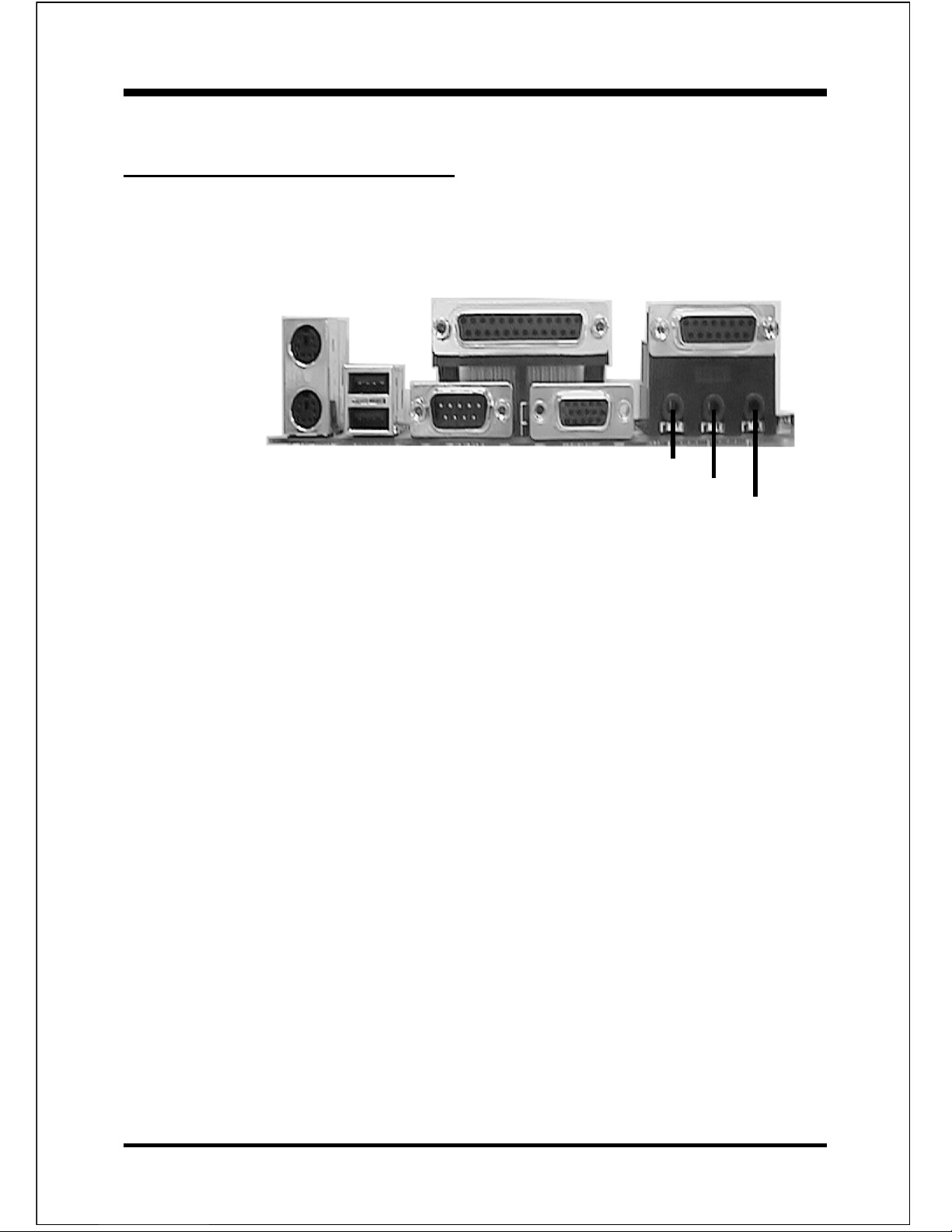
Device Connectors
Please install the motherboard into the chassis.
PS/2 Mouse
PS/2
KEYBOARD
COM1VGA1
parallel port
Speaker
Joystick/Midi
USB port
Line_in
MIC
Figure 6
J2:Chassis Panel Connector
• Power LED, Speaker, Reset
J3:Power_ON/OFF, Turbo LED, HDD LED, IR Connector
J4:CPU Fan Power
• A plug-in for the CPU Fan Power
J6:Chassis Fan Power
• A plug-in for the chassis Fan Power
J7:WOL (Wake On
LAN) Connector
IDE1: Primary IDE Connector
IDE2: Secondary IDE Connector
FDD1: Floppy Controller Connector
PW1: ATX Power Connector
• 20-pin power connector
CD1: CD-ROM Audio_in Connector
MODEM1: Telephony Connector
• Pin1(Audio_in), Pin2/Pin3(GND), Pin4(Mic-out to Modem)
Page 9

InstallationMVP4F
Page 9
Device Connectors (continued)
J2
Speaker - Connect to the system's speaker for beeping
1. Speaker3. GND
2. N/C4. GND
Reset - Closed to restart system.
Power LED - Power LED connector
1. Power LED(+)4. NC
2. N/C5. GND
3. GND
1
1
1
(This is connected to the power button on the case. Using the
Soft-Off by Pwr-BTTN feature, you can choose either Instant
Off (turns system off
immediately), or 4 sec delay (you need to
hold the button down for 4 seconds before the system turns off).
When the system is in 4 sec delay mode, there is a special feature
to make the system to go into suspend mode when the button is
pressed momentarily.)
Turbo LED indicator - LED ON when higher speed is selected
IDE LED indicator - LED ON when Onboard PCI IDE Hard
disks is activate
J3
1
+
+
IR Connector
1. VCC 4. GND
2. NC 5. IRTX
3. IRRX
1
Power On/Off
 Loading...