

Page 1

MVP3E
ISA/PCI/AGP
MotherBoard
with Onboard PCI IDE and Super Multi-I/O.
Apollo MVP3 AGPset
The specification is subject to change without notice.
TRADEMARK
All products and company names are trademarks or registered
trademarks of their respective holders.
V034
Page 2

Introduction
Chapter 1
Introduction
This motherboard is a high performance system hardware based on Intel
Pentium processor and is equipped with an AGP slot, four PCI slots, three
standard ISA slots, Super Multi-I/O controller and dual port PCI-IDE
connectors for the future expansion. The hardware dimension is 305mm x
230mm with a four-layer-design technology.
Specification
VIA Apollo MVP3 AGP/PCIset chipset.
Intel Pentium Processor, Pentium Processor with MMX technology, AMD
K5/K6, Cyrix 6x86L/6x86MX & idt C6 operating at 120 ~ 500 MHz with 321
ZIF socket 7 provides scalability to accept faster Processors in the future.
Supports up to 384 MegaBytes of memory (168-Pin DIMM SOCKET x 3
and 72-Pin SIMM SOCKET x 2 ).
Supports 512KB/1024KB (Optional) L2 Cache.
Supports three 16 bit ISA slots ,four 32 bit PCI slots and an AGP slot and
provides two independent high performance PCI IDE interfaces capable of
supporting PIO Mode 3/4 and Ultra-DMA33 devices.
Supports ATAPI (e.g. CD-ROM) devices on both IDE interfaces.
Supports a floppy port, a parallel port (EPP,ECP port), two serial ports
(16550 Fast UART compatible), 2 USB Ports, a PS/2 style mouse connecter
and a PS/2 style keyboard connector.
Supports Award Plug & Play BIOS.
Supports CPU Hardware sleep, APM (Advanced Power Management) and
ACPI (Advanced Configuration Power Interface).
Supports an ATX power supply connector for a Remote On/Off , a Phone-
Ring Power On and a Keyboard Power On Function.
Supports Switching Regulator for CPU power supply. and single jumper for
CPU working voltage selection.
Supports ESDJ (Easy Setting Dual Jumper) function for CPU selection.
Support hardware monitor function.
R
Page 3
MVP3E
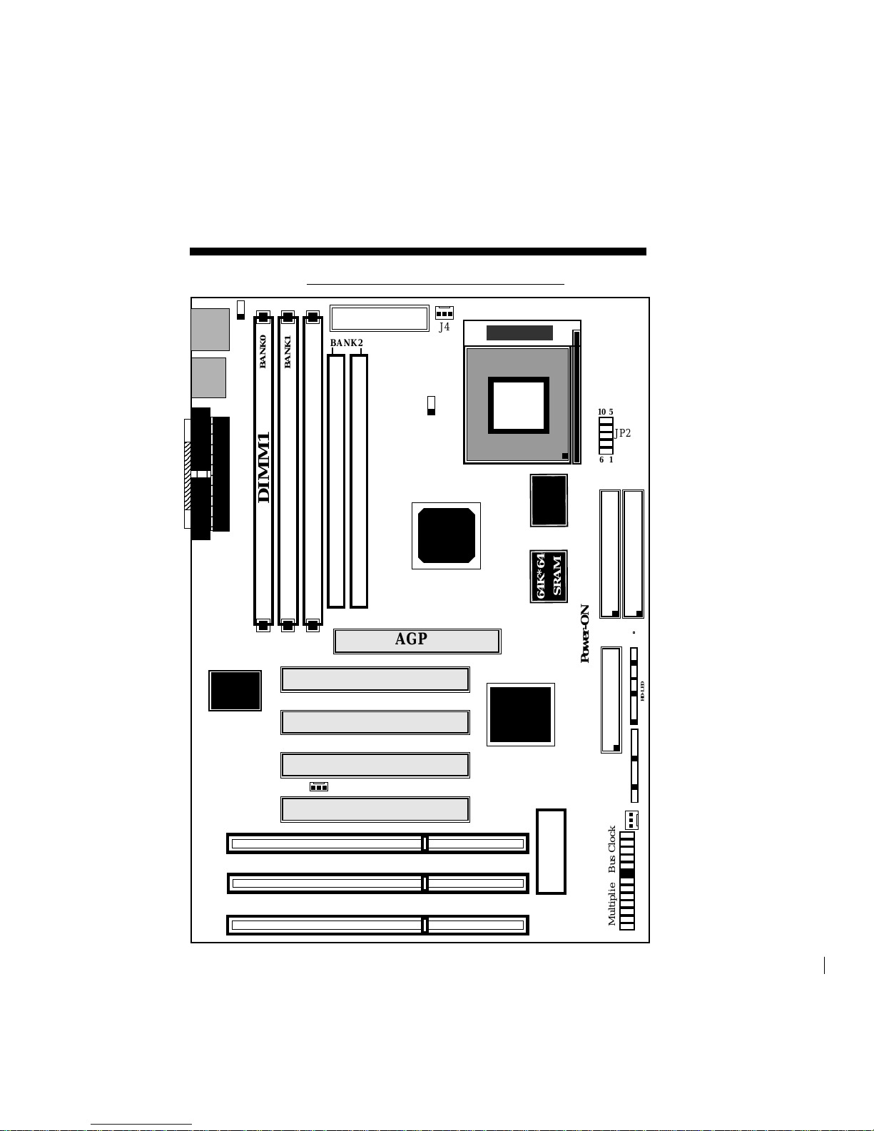
Figure 2-1
ATX Power Conn.
Winboand
83877F
DIMM3
DIMM2
PCI#2
PCI#3
PCI#4
PCI#1
<
BIOS
SPEAKER TB-LEDRESET KEYLOCK
MVP3E Layout
FDD CONN.
Secondary IDE
IR CONN
JP3
1
BANK2
SIMM 1
SIMM 2
2
586B
598AT
SOCKET 7
Primary IDE
FDD1
J6
64K*64
SRAM
COM1
PS/2
MOUSE
K/B
PRINTER PORT
COM2
USB
PORT
2
3
2
3
2
3
2
3
2
3
2
3
2
3
2
3
2
3
2
3
2
3
2
3
2
3
2
3
DIMM1
1
5
JP2
6
10
BANK1
BANK0
BANK2
J4
HD-LED
Power-ON
64K*64
SRAM
AGP
Bus ClockMultiplier
+ +
<=======
<=
1 51 5
JP5
JP4
J7
1
1
(Optional)
Page 4

Hardware Design
JP2 : CPU Vcore voltage selection : For Pentium Processor with MMX technology,
AMD K6 and Cyrix 6x86L/6x86MX/M II
6-12: 3.2V for AMD K6-PR2-233MHz
5-11: 2.9V for AMD K6-PR2-166/200MHz and Cyrix 6x86 MX/M II
4-10: 2.8V for Pentium MMX and Cyrix 6x86L
3-9: 2.4V Reserved
2-8: 2.2V for AMD K6 3D CPUs
1-7: 2.1V Reserved
6 12
1 7
JP3
Pentium / MMX JP3 Cyrix / IBM
AMD K5 / K6 6x86L
idt - C6 Multiplier Bus CLOCK 6x86MX
25 26
2-2 Connectors and Jumpers
This section describes the connectors and jumpers equipped in the motherboard.
Please refer to Figure 2-1 for the location of each connector and jumper.
1 2
5 X
4.5 X
4 X
3.5 X
3 X
2.5 X
2 X
100MHz
83MHz
75MHz
66MHz
60MHz
Multiplier
Bus CLOCK
2 x
2.5 x
3 x
3.5 x
4 x
133MHz 66MHz L/MX-PR166
150MHz 75MHz L/MX-PR200
150MHz 60MHz MX-PR166
166MHz 66MHz MX-PR200
188MHz 75MHz M II/MX-PR233
210MHz 83MHz M II/MX-PR266
250MHz 100MHz M II/MX-PR333
180MHz 60MHz
200MHz 66MHz M II/MX-PR233
225MHz 75MHz M II/MX-PR300
250MHz 83MHz M II/MX-PR333
300MHz 100MHz M II/MX-PR350
233MHz 66MHz M II/MX-PR300
263MHz 75MHz M II/MX-PR333
290MHz 83MHz M II/MX-PR350
350MHz 100MHz
240MHz 60MHz
266MHz 66MHz M II/MX-PR333
300MHz 75MHz M II/MX-PR350
333MHz 83MHz
400MHz 100MHz
Page 5

MVP3E
1
J3
IrDA/ASK IR CONNECTOR
5
1. Power LED(+)
2. N/C
3. GND
4. Key-Lock
1
5
4
1. Speaker
2. N/C
3. GND
4. VCC
J2
1
Reset Switch - Closed to restart system.
Speaker - connect to the system's speaker for beeping.
KeyLock - Keyboard lock switch & Power LED connector.
Turbo LED indicator - LED ON when higher speed is selected.
IDE LED indicator - LED ON when harddisks activate.
# There is no deturbo function so that the turbo LED is always ON.
5. GND
+
1. VCC
2. NC
3. IRRX
4. GND
5. IRTX
+
Power-ON - Push the button to turn on the system.
- Pressing less than 4 seconds to enter the suspend mode
- Pressing more than 4 seconds to turn off the system
J4
J6
CPU FAN Connector
CHASSIS FAN Connector
J7
WOL(Wake-up On LAN) Connector
Page 6

Hardware Design
2-3 System Memory Configuration
This motherboard supports different type of settings for the system memory. The
following figures and table provides all possible memory combinations.
>
12
>
DIMM2
32MB x 1
16MB
MAX.= 384MB
8MB
BANK 0
BANK 2
128MB
>
12
DIMM3
BANK 1
12
12
DIMM1
64MB
32MB x 1
16MB
8MB
128MB
64MB
32MB x 1
16MB
8MB
128MB
64MB
DIMM 1 DIMM 2 DIMM 3 or SIMM1&2 TOTAL
BANK 0 BAMK 1 BANK 2 MEMORY
This motherboard supports 2 kinds of powerful and flexible SDRAM frequency
selections. These can be synchronous with CPU bus clock or fixed as 66MHz. By
implementing the VCS (Virtual Clock Synchronization) technology, this
motherboard
refers to the use of delay-lock-loop (DLL) to enable synchronous and pseudosynchronous operation of the processor and DRAM, AGP and PCI buses. The JP5
allows user to set the SDRAM Frequency between 66/100MHz.
1
JP5 SDRAM Clock Selection
1-2 : Fixed as 66MHz
2-3 : SDRAM Clock = CPU Bus Clcok
Jumper's position:
1-2 : Pseudo-synchronous Status(Fixed as 66MHz)
A more stable and compatible operation condition for non-100MHz based SDRAM
when you are using 100MHz based CPU. This setting is suitable for those users who
are like to remain the usage of current SDRAM module.
2-3 : Synchronous Status(SDRAM Clock= CPU Bus Clock)
Increasing the bus speeds from the traditional 66MHz to 100MHz greatly improves
system performance because the speed at which data traveling between the CPU and
memory is increased by 50%. However, there is one thing you should bear in mind.
Please make sure you are using 125MHz(-8) based or above SDRAM module.
12
12
12
12
>
BANK 2
SIMM1
SIMM2
16MB x 2
8MB
32MB
or
Page 7

Hardware Design
2-5 External Modem Ring-in Power ON and Keyboard Power ON
Functions
On the basis of bounded functions in I/O chipset, the two serial ports are able to
support the External Modem Ring-in Power ON function. Once users connect the
external modem to COM1 or COM2, this motherboard allows users to turn
on their system through the remote and host's dial-up control.
Exclusive Keyboard Power ON Function
To innovate a unique feature to benefit users, we devoted ourselves to create the
easiest and most convenient way to turn on your system based on the ATX
power supply. This function is available only under system being connected to
ATX power supply.
How to work with it
Step 1: Please place JP4 at the position 2-3 after you finished the system installation.
Step 2 : Push the momentary switch to turn on your system and then push again to
hold for more than 4 seconds to turn it off as soon as you turn it on.
Step 3: You can enjoy the Keyboard Power ON function by pressing any 1 or 2
keys on you keyboard at the same time for 1-2 seconds. Your system will be
turned on automatically, after releasing the keys. To power off you system,
you can use the Soft-OFF function under Windows 95.
Notes:
1. The number of keys needed to turn on a system depends on the model of
keyboard you are
applying due to different loadings on different keyboards.
Here, we would like to suggest you push 2 keys at the same time..
2.Intel ATX version 2.0 specification has recommended you use the power
supply with 0.72A(720mA). With our EP-51MVP3E-M
motherboard,
the 5.0VSB
standby power only has to be > = 0.1A (100mA) then you can enjoy this
unique benefit. However, the ATX power supply which is < 0.1 (100mA) is still
applicable to your system by placed JP4 at the position 1-2 to disable this
feature.
1
3
JP4 Keyboard Power-ON Function Selection
1-2 : Disabled
2-3 : Enabled
 Loading...