

Page 1

MVP4A
ISA/PCI Motherboard with Onboard AGP
VGA PCI Audio, PCI IDE and Super
Multi-I/O
TRADEMARK
All products and company names are trademarks or registered
trademarks of their respective holders.
These specifications are subjected to change without notice.
Manual Revision 3.1
June 21, 1999
Page 2

MVP4A Features:
FeaturesMVP4A
FEATURES
• Intel Pentium
K5/K6, Cyrix 6x86L/6x86MX & idt C6 operating at 133 ~ 450 MHz with
321 ZIF socket 7 provides scalability to accept faster Processors in the
future.
®
Processor, Pentium Processor with MMX technology, AMD
• Designed with VIA MVP4 AGPset.
• Supports up to 384 MB of DRAM (minimum of 16 MB) on board, You can
use 168-pin DIMM x 3. It will automatically detect Extended Data Output
(EDO) DRAM at 66MHz only or Synchronous DRAM memory (SDRAM) at
66MHz or 100MHz.
• Supports (2) 16 bit ISA slots, (4) 32 bit PCI slots, and provides (2) independent
high performance PCI IDE interfaces capable of supporting PIO Mode 3/4
and Ultra DMA 33/66 devices. The MVP4A supports (4) PCI Bus Master
slots and a jumperless PCI INT# control scheme which reduces configuration
confusion when plugging in PCI card(s).
• Supports ATAPI (e.g. CD-ROM) devices on both Primary and Secondary IDE
interfaces.
• Designed with lntegrated Multi I/O: (1) floppy port, (1) parallel port (EPP,
ECP), and (2) serial ports (16550 Fast UART).
Note: Japanese “Floppy 3 mode” is also supported
• Features Award Plug & Play BIOS. With Flash Memory you can always
upgrade to the current BIOS as they are released. (http://www.2themax.com
please visit our T echnical Support section for the latest updates).
• MVP4A utilizes a Lithium battery which provides environmental protection
and longer battery life.
• Software power-down when using Windows
®
95/98.
• Supports ring-in feature (remote power-on through external modem,
allows system to be turned on remotely).
Page 2
Page 3

Features MVP4A
• Resume by Alarm - Allows your system to turn on at a preselected time.
• Supports CPU Hardware sleep and SMM (System Management Mode).
• Supports Keyboard power ON function (KBPO).
• Supports USDM software to offer motherboard various status.
• Supports the CPU and Chassis fan Auto stop in sleep mode.
• Built-in WOL (Wake On Lan) Connector.
• Built-in Sound Blaster compatible/DirectSound AC97 Audio.
• Built-in AGP 2D/3D Graphics Accelerator.
Page 3
Page 4

Installation MVP4A
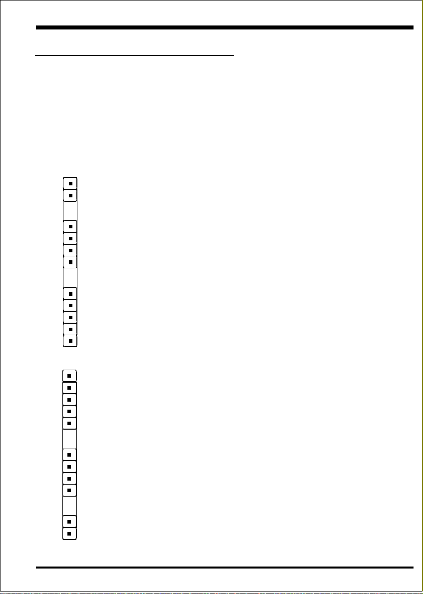
MVP4A Detailed Layout
PS/2
USB 1
(Top)
USB
USB 0
(Bottom)
COM 1
Parallel Port
VGA
Game Port
USB CONN.
Mouse
(Top)
Keyboard
(Bottom)
CD1
JP4
1
COM2
AUX1
PCI Slot #1
PCI Slot #2
PCI Slot #3
PCI Slot #4
Flash Memory
for BIOS
ISA Slot #1
SOCKET 7
J7:WOL
Battery
J4
CPU FAN
VIA
VT8501
Bank 2
ON
DIMM 3
VT82C686 A
JP1
1
Bank 1
DIMM 2
VIA
FDD1
Bank 0
DIMM 1
PW1
IDE1
JP3
J6
Secondary IDE
IDE2
J3
1
+
+
5
1
5
1
1
1
J2
Chassis FAN
POWER_ON/OFF
IR CONN.
Power LED
SPK
RESET
Page 4
ISA Slot #2
Figure 1
Page 5

InstallationMVP4A
Easy Installation Procedure
The following must be completed before powering on your new system:
Configure Jumpers
System Memory Configuration
Device Connectors
Configure Jumpers
We design this motherboard with the fewest jumpers to make your install fast and
easy.
The following will describe all of the jumpers that you are required to set before
moving on to step 2.
Note: The jumpers as depicted as shown (Figure 1) in their correct physical
orientation.
JP1 CMO S C lear
JP1 = 1-2 - Run Mode (Default)
= 2 -3 - Clea r CMOS (mo mentar ily )
D isabled(D efau lt)
= 2 -3 -
Enabled
JP4
1
K eyboard P ower-ON function (refer to the section 3-4)
JP4 = 1-2 -
1
J7 WO L (Wak e On La n) Co nn ector
R eserved for N IC (N etw o rk Interface Ca rd) to
Wake the System.
Page 5
Page 6

Installation MVP4A
SW1: CPU Vcore Voltage Selection
S W 1 CP U
ON
1234
JP3: CPU Speed Selection
5
3
2
1
ON
ON
ON
ON
ON
ONON
ON
ON
4
ON
ON
ON
ONON
ON
5
ON
ON
Vcore
1.8V
2.0V
2.1V
2.2V
2.3V
2.4V
2.8V
2.9V
3.2V
ESDJ
* Reserved
XMM/muitneP
6K/5KDMA
6C-TDI
zHM661
zHM052zHM001663RP
ZHM002
zHM052zHM38333RP
zHM003zHM001334RP*
zHM332
zHM333zHM59664RP*
zHM053zHM001005RP*
zHM662
zHM333zHM38664RP*
zHM083zHM59335RP*
zHM004zHM001055RP*
zHM003
zHM054zHM001
zHM333
zHM574zHM59
zHM005zHM001
zHM663X5.5zHM66
X3
X4
X5
3PJ
reilpitluMkcolCsuB
zHM66002RP
zHM57332RP
X5.2
X5.3
X5.4
zHM38662RP
zHM59003RP
zHM66662RP
zHM57003RP
zHM59004RP*
zHM66003RP
zHM57333RP
zHM38004RP*
zHM66333RP
zHM57004RP
zHM66
zHM66
MBI/xiryC
IIM/XM68x6
Page 6
Page 7

InstallationMVP4A
System Memory Configuration
Memory Layout
The MVP4A supports (3) 168-pin DIMMs (Dual In-line Memory Module). The
DIMMs can be either EDO (Extended Data Out) or SDRAM (Synchronized
DRAM). The DIMMs may be installed using just one chip.
• We r ecommend using SDRAM DIMM can not mixing
with EDO DIMM modules.
• DIMM SDRAM may be 83MHz (-12ns), 100MHz (-10ns) or
125MHz (-8ns) bus speed.
• No Registered DIMM support.
Figure 2 and T able 1 show several possible memory configurations using
DIMM 1
DIMM 2
DIMM 3
yromeMlatoT
BM821=
mumixaM
BM652=
mumixaM
BM483=
mumixaM
1MMID
)0knaB(
*MARDS/ODE
,BM23,BM61,BM8
1XBM821,BM46
*MARDS/ODE
,BM23,BM61,BM8
1XBM821,BM46
*MARDS/ODE
,BM23,BM61,BM8
1XBM821,BM46
enoNenoN
Bank 0
Bank 1
Bank 2
2MMID
)1knaB(
*MARDS/ODE
,BM23,BM61,BM8
1XBM821,BM46
*MARDS/ODE
,BM23,BM61,BM8
1XBM821,BM46
-Synchronous
-EDO
3MMID
)2knaB(
enoN
*MARDS/ODE
,BM23,BM61,BM8
1XBM821,BM46
Table 1
* SDRAM only supports 8, 16, 32, 64, 128MB DIMM modules.
* We recommend to use PC100 Memory Module for bus speed between 100MHz
and 66MHZ.
Page 7
Page 8

Installation MVP4A
Device Connectors
Please install the motherboard into the chassis.
Now that your motherboard is installed you are ready to connect all your connections
(figure 6).
parallel port
Joystick/Midi port
PS/2 Mouse
PS/2
KEYBOARD
USB port
COM1 VGA1
J4: CPU Fan Power
• A plug-in for the CPU Fan Power
J6: Chassis Fan Power
• A plug-in for the chassis Fan Power
J7: WOL (Wake On Lan) Connector
PW1: ATX Power Connector
• 20-pin power connector
J2,J3: Chassis Panel Connector
• Power_LED, Speaker, Reset, Sleep, Turbo LED and HDD LED
IDE1: Primary IDE Connector
IDE2: Secondary IDE Connector
Speaker
Line_in
MIC
Figure 6
FDD1: Floppy Controller Connector
CD1: CD-ROM Audio_in
AUX1: AUX Audio_in
COM2:
RS232 COM2 Connector
USB CONN.: The third and fourth USB port (cable optional)
Page 8
Page 9
Device Connectors (continued)
(This is connected to the power button on the case. Using the
Soft-Off by Pwr-BTTN feature, you can choose either Instant
Off (turns system off immediately), or 4 sec delay (you need to
hold the button down for 4 seconds before the system turns off).
When the system is in 4 sec delay mode, there is a special feature
to make the system to go into suspend mode when the button is
pressed momentarily.)
J3
+
+
Power On/Off
1
T urbo LED indicator - LED ON when higher speed is selected
IDE LED indicator - LED ON when Onboard PCI IDE Hard
disks is activate
IR Connector
1. VCC 4. GND
2. NC 5. IRTX
3. IRRX
1
InstallationMVP4A
J2
Power LED - Power LED connector
1. Power LED(+) 4. NC
2. N/C 5. GND
3. GND
1
Speaker - Connect to the system's speaker for beeping
1. Speaker 3. GND
2. N/C 4. GND
1
Reset - Closed to restart system.
1
Page 9
 Loading...