

Page 1
BXB (SMP)
A Dual Pentium® II Processor based
AGP motherboard (100/66MHz) with
Adaptec Ultra-2 SCSI onboard.
TRADEMARK
All products and company names are trademarks or registered
trademarks of their respective holders.
These specifications are subjected to change without notice.
Manual Revision 1.1
July 15, 1999
Page 2

BXB Features:
FeaturesBXB
FEATURES
• BXB is based on the Dual Pentium
MHz (66MHz) or 300-450 MHz (100MHz) on Slot 1. The board is configured
by an Easy-Setting-Single-Jumper (E.S.S.J.) to match your CPU clock speed.
®
II Processor operating at 233 ~ 333
• Designed with Intel’s 82443 BX AGPset.
• Supports up to 1 Gigabyte of SDRAM (minimum of 8 MB) on board, You can
use 168-pin DIMM x 4. It will automatically detect Extended Data Output
(EDO) DRAM or Synchronous DRAM memory (SDRAM)
• BXB will support Error Checking and Correcting (ECC) when using
parity DRAM memory modules. This will detect multiple bit errors and correct
1-bit memory errors.
• Supports (2) 16 bit ISA slots, (4) 32 bit PCI slots, (1) AGP slot and provides
(2) independent high performance PCI IDE interfaces capable of supporting
PIO Mode 3/4 and Ultra DMA 33 devices. The BXB supports (4) PCI
Bus Master slots and a jumperless PCI INT# control scheme which reduces
configuration confusion when plugging in PCI card(s).
• Supports ATAPI (e.g. CD-ROM) devices on both Primary and Secondary IDE
interfaces.
• Designed with Adaptec AIC-7890 Ultra-2 Wide SCSI for LVD (80 Mbytes/
sec) devices and Adaptec AIC-3860 for legacy single-ended SCSI devices.
(please see Section 3-6).
• Designed with Winbond W83977 Multi I/O: (1) floppy port, (1) parallel port
(EPP, ECP), and (2) serial ports (16550 Fast UART), (1) IrDA.
Note: Japanese “Floppy 3 mode” is also supported
• Includes a PS/2 mouse connector.
• Allows use of a PS/2 or AT keyboard (with optional adapter).
Page 2
Page 3

Features BXB
• Features Award Plug & Play BIOS. With Flash Memory you can always
upgrade to the current BIOS as they are released. (http://www.2themax.com/
please visit our Technical Support section for the latest updates)
• BXB utilizes a Lithium battery which provides environmental protection
and longer battery life.
• Supports the Universal Serial Bus (USB) connector. The onboard PIIX4 chip
provides the means for connecting PC peripherals such as keyboards,
joysticks, telephones, and modems.
• Built-in ATX 20-pin power supply connector.
• Software power-down when using Windows
®
95/98.
• Supports ring-in feature (remote power-on through external modem,
allows system to be turned on remotely).
• Power on by Alarm - Allows your system to turn on at a preselected time.
•Power Loss Recovery - In the event of a power outage your system will
automatically turn itself back on without user intervention.
• Supports CPU Hardware sleep and SMM (System Management Mode).
• Supports Desktop Management Interface (DMI) facilitating the management
of desktop computers, hardware and software components and peripherals,
whether they are stand-alone systems or linked into networks. (option)
• Supports Hot Key, Any Key, or password Keyboard power ON function
(KBPO).
®
• Supports USDM software which allows Windows
0 to monitor various aspects of the system hardware.
• Supports stopping the CPU, AUX, and Chassis FANs during sleep mode.
• Supports blinking of the System Power LED (PANEL) during sleep mode.
95/98, or Windows® NT 4.
• Built-in WOL (Wake On Lan) Connector.
• Built-in SB-LINK Header for Creative Labs Sound Blaster
sound card.
Page 3
®
AWE64D PCI
Page 4
Installation BXB
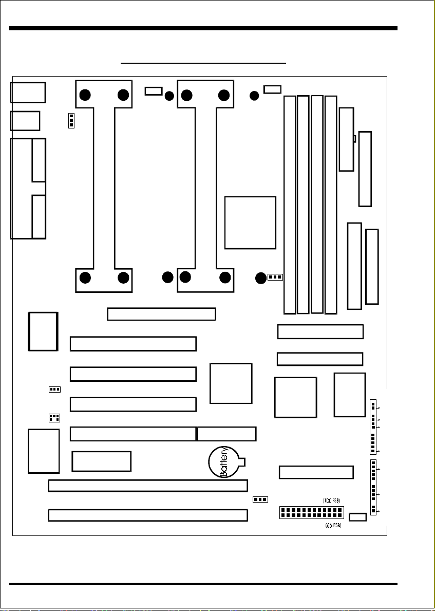
BXB Detailed Layout
PS/2
USB
Parallel Port
USB 1
(Top)
USB 0
(Bottom)
COM 1COM 2
Winbond
J7
J1
Intel
Mouse
(Top)
Keyboard
(Bottom)
I/Oset
83977
82093A
1
Wake On- Lan
SB-Link
KBPO
JP13
CPU Cartridge SLOT 1
PCI Slot #1
PCI Slot #2
PCI Slot #3
PCI Slot #4
Flash Memory
for BIOS
ISA Slot #1
ISA Slot #2
1
CPU 1
Fan
J4
Primar y
AGP SLOT
Secondary
Intel
443BX
CPU Cartridge SLOT 1
PCIset
Intel
PIIX4
PCIset
SCSI RAID (option)
Clear
CMOS
JP1
1
1
Bank 0
CPU 2
IDE2
IDE1
Fan
J5
JP100
1
1
Bank 1
DIMM 1
DIMM 2
Secondary IDE
Primar y IDE
Adaptec
AIC
7890
Ultra-2 SCSI (LVD)
300
350
400
450
500
550
200
233
266
300
333
366
Bank 2
Bank 3
ATX Pow er Input
PW1
FDD Connector
1
FDD1
SCJ2
Adaptec
1
Chassis
Fan
J6
1
Narrow SCSI (legacy)
1
AIC-3860
J3
J2
SCJ1
Wide SCSI (legacy)
1
PWR/ON
TBLED
H/D LED
IR
KEYLOCK
/PWR LED
SPEAK
RST
DIMM 3
DIMM 4
SCJ3
MHz
MHz
Page 4
Figure 1
Page 5

InstallationBXB
Easy Installation Procedure
Easy Installation Procedure
The following must be completed before powering on your new system:
Configure Jumpers to match your hardware
Install memory chips
Device Connectors
Device Connectors
Adaptec SCSI setup
Configure Jumpers
2theMax designs all motherboards with the fewest jumpers to make your setup fast and
easy.
The following will describe all of the jumpers that are required to be set before
moving on to step 2.
Note: The jumpers as shown in Figure 1 are in their correct physical
orientation.
JP1:
1
CMOS Clear
JP1: = 1-2 - Run Mode (Default)
= 2-3 - Clear CMOS
JP13:
Keyboard Power-ON function (see page 3-12)
JP13: = 1-2 - Enable
J1:
1
SB-LINK Header:
= 2-3 - Disable (Default)
Reserved for Creative Labs A WE64D PCI sound card
which allows for DOS mode compatibility.
J7:
WOL (Wake On Lan):
Reserved for NIC (Network Interface Card) which when
used with compatible software will allow the system to be
powered on remotely using a network connection.
Page 5
Page 6

Installation BXB
Single or Dual Processor Selection
ESSJ
CPU Clock Rate
66MHz FSB
200MHz
233MHz
266MHz
300MHz
333MHz
(RSD) 366MHz
JP3:
1
NOTE: Based on the implementation of the Intel 440BX AGPset the BXB is
able to provide two front side bus (FSB) frequencies -- either 66MHz or 100MHz
for Slot 1 processors and memory operations. The
detect the correct FSB and set accordingly unless JP100 is set otherwise (see
jumper JP100 below). The primary and secondary processor slots both operate
synchronously at either 66MHz or 100MHz FSB, therefore if two processors are
used both will need to be of the same type and speed; otherwise the lower of the
two FSB frequencies will be set. When using the 100MHz FSB you must use
PC100 compliant SDRAM.
CPU Clock Rate
100MHz FSB
300MHz
350MHz
400MHz
450MHz
500MHz (RSD)
550MHz
(RSD)
* Default at 266MHz (66MHz FSB)
* RSD (Reserved for future use)
motherboard will automatically
Memory is an important component of any 100MHz motherboard. When selecting
memory for use on your
2theMax brand motherboard we recommend using only the
finest quality modules. 2theMax would like to stress that using non-compliant PC100
SDRAM modules with a 100MHz FSB severely compromises the integrity of the
system.
JP100:
1
(FSB) Bus Clock Selection
JP100: = 1-2 - AUTO (Default)
= 2-3 - PC100 Only (100MHz FSB)
Page 6
Page 7

InstallationBXB
System Memory Configuration
Memory Layout
The BXB supports (4) 168-pin DIMMs (Dual In-line Memory Module). The
DIMMs can be either EDO (Enhanced Data Out) or SDRAM (Synchronized
DRAM). Do not mix EDO DIMM and SDRAM DIMM in the system.
• SDRAM DIMM may be 100 MHz (10ns) or 125 MHz (8ns) bus speed.
• SDRAM DIMM may be 8MB, 16MB, 32MB, 64MB, 128MB, or 256MB
registered (see table 2).
• 100MHz FSB frequency requires PC100 compliant SDRAM memory.
• 4 clock SDRAM is recommended instead of 2 clock.
• If using 50ns and 60ns EDO DIMM together you must set BIOS for 60ns.
• Table 1 shows several possible memory configurations.
• Table 2 shows compatible SDRAM components types according to Intel
440BX datasheets. (Internet: http://developer.intel.com)
yromeMlatoT 1MMID 2MMID 3MMID 4MMID
BG1=
mumixaM
BM867=
mumixaM
BM215=
mumixaM
BM652=
mumixaM
MARDS/ODE
BM23,BM61,BM8
M652,BM821,BM46
1X
MARDS/ODE
BM23,BM61,BM8
M652,BM821,BM46
1X
MARDS/ODE
,BM23,BM61,BM8
BM652,BM821,BM46
1X
MARDS/ODE
,BM23,BM61,BM8
BM652,BM821,BM46
1X
noitpOMARDS epyTtnenopmoCMARDS
MARDS/ODE
,BM23,BM61,BM8
BM652,BM821,BM46
1X
MARDS/ODE
,BM23,BM61,BM8
BM652,BM821,BM46
1X
MARDS/ODE
,BM23,BM61,BM8
BM652,BM821,BM46
1X
enoNenoNenoN
MARDS/ODE
,BM23,BM61,BM8
1X
1X
enoNenoN
BM652,BM821,BM46
1X
MARDS/ODE
,BM23,BM61,BM8
enoN
BM652,BM821,BM46
Table 1
MARDS/ODE
,BM23,BM61,BM8
BM652,BM821,BM46
BM861xM1
BM6123xM2ro8xM2
BM23*4xM4ro61xM4
BM468xM8
BM821*4xM61
Table 2
* Registered DIMM only.
Page 7
Page 8

Installation BXB
Device Connectors
Please install the motherboard into the chassis.
Now that your motherboard is installed you are ready to connect all your connections
(figure 12).
PS/2 Mouse
(T op)
PS/2 Keyboard
(Bottom)
USB 1
(T op)
USB 0
(Bottom)
Figure 12
Parallel Port
(T op)
Com1 Com2
(Bottom Left) (Bottom
Right)
FDD1:Floppy controller
IDE1:Primary IDE
IDE2:Secondary IDE
J1: SB-Link
J2/J3:Chassis panel connector
(Keylock, Speaker, Reset, Turbo, Sleep, and HDD LED)
J4: CPU 1 fan power (plug-in for compatible FANs which allow monitoring)
J5: CPU 2 fan power (plug-in for compatible FANs which allow monitoring)
J6: Chassis fan power (plug-in for compatible FANs which allow monitoring)
J7: Wake-On-Lan (WOL)
PW1: ATX power connector (20-pin power connector)
SCJ1:68-pin wide SCSI for legacy single-ended (SE) SCSI devices
SCJ2:50-pin narrow SCSI for legacy single-ended (SE) SCSI devices
SCJ3:68-pin wide SCSI for Ultra-2 LVD SCSI devices
Page 8
Page 9

Device Connectors (continued)
Power On/Off - This is connected to the power button on the case.
Using the Soft-Off by Pwr-BTTN feature, you can choose either
Instant Off (turns system off
hold the button down for 4 seconds before the system turns off).
When the system is in 4 sec delay mode, 2theMax has added a special
J3
Power On/OffIDE & TurboInfraredPwr LED & KeylockSpeakerReset
feature to make the system go into suspend mode when the button is
1
pressed momentarily.
Turbo LED indicator - LED ON when higher speed is selected
+
IDE LED indicator - LED ON when Onboard PCI IDE Hard disks is
+
activate
Infrared - Infrared connector
1. Vcc 4. GND
2. IRTX 5. IRTX2
1
3. IRRX2
InstallationBXB
immediately), or 4 sec delay (you need to
J2
KeyLock - Keyboard lock switch & Power LED connector
1. Power LED(+) 4. Keylock
2. N/C 5. GND
1
3. GND
Speaker - Connect to the system's speaker for beeping
1. Speaker 3. GND
1
1
2. N/C 4. GND
Reset - Closed to restart system.
Page 9
Page 10

Adaptec SCSI Setup
Introduction
InstallationBXB
The BXB
motherboard features the advanced Adaptec AIC-7890 Ultra-2 Wide
SCSI controller. This controller provides support for Low Voltage Differential
(L VD) SCSI devices as defined under the Ultra-2 section of the SCSI-3 standard.
L VD SCSI devices allow for data transfer rates of up to 80 Mbytes/sec and can
use cable lengths of up to 12 meters! Additionally the AIC-3860 Adaptec controller is also provided for backwards compatibility with single-ended (SE) legacy
SCSI devices such as SCSI-1, Fast, Fast Wide, Ultra and Ultra W ide.
Hardware Setup and Connector Descriptions
The motherboard can have attached a total of 15 SCSI devices. The 15 devices can be a combination of LVD Ultra-2 devices and/or SE Legacy devices
but note that the SE Legacy controller can support up to 8 devices only!
Provided on the motherboard are three SCSI connectors. The first two being SCJ1
and SCJ2 are provided for single-ended (SE) legacy SCSI devices and will operate at a data transfer rate of 40 Mbytes/sec (max.) using the 68-pin “Wide” connector and 20 Mbytes/sec (max.) using the 50-pin “Narrow” connector. It is strongly
recommended that all legacy SCSI devices be connected to either one of these two
connectors. Due to the design characteristics of SE mode devices the cable length
per connector should never exceed 3 meters with up to 4 SCSI devices and 1.5
meters with up to 8 SCSI devices.
External SCSI devices can be connected to the SCSI bus through the
use of the included “external SCSI-2 port adapter.” To use external
SCSI devices simply use onboard connector SCJ2 with an internal 50pin SCSI cable. One end of the cable must attach to SCJ2 and the other
end connects to the external port adapter. Internal SCSI devices can still
be used, but just not on the ends of the cable.
Page 10
Page 11

Installation BXB
The last connector labeled SCJ3 is a single 68-pin “Wide” connector for LVD
mode SCSI devices operating at a maximum data transfer rate of 80 Mbytes/sec.
The maximum cable length that can be used is 12 meters with up to 15 SCSI L VD
devices. It is strongly recommended that no single-ended (SE) legacy SCSI devices
be used on this connector as performance will drop to a 40 Mbytes/sec maximum
with device and cable length limitations of the above first two connectors!
SCSI Bus Termination
Proper operation of the SCSI bus requires the following: each device must have a
unique SCSI ID (including the SCSI controller) and the SCSI chain must have
termination on each of the 3 onboard connectors. Termination is required at the last
device on each SCSI cable.
T ermination for the majority of devices are accomplished by enabling a jumper or
terminator resistor. No terminator is required for the SCSI controller onboard the
motherboard as this will be set automatically. When using the “external SCSI-2 port
adapter” the external SCSI device must provide termination.
The Ultra-2 (LVD) cable is provided with a terminator which attaches to the end of
the cable.
Page 11
Page 12

InstallationBXB
SCSI Bus Overview Diagram
15 SCSI Devices Maximum! Also note each controllers drive number limitations.
SE
AIC-7890
LVD
Ultra2
Drive
Ultra2
Drive
Ultra2
Drive
Ultra2
Drive
Ultra2
Drive
Ultra2
Drive
. . .
SE
SCJ3 wide 68-pin
LVD
SE
LVD
LVD
AIC-3860
SE
LVD
Cable length: 12 m eters (up to 15 devices)
Throughput: 80M bytes/sec (SC J3 wide 68-pin)
SCJ1 wide 68-pin
SCJ2 narro w 50 -pin
SE
SE
LVD
Legacy
Drive
SE
SE
Cable length:
3.0 m eters (up to 4 devices)
1.5 m eters (up to 8 devices)
Throughput:
40M bytes/sec (SC J1 wide 68-pin)
20M bytes/sec (SC J2 narrow 50-pin)
LVD
Legacy
Drive
SE
SE
LVD
Legacy
Drive
SE
SE
LVD
Legacy
Drive
SE
Figure 13
Page 12
 Loading...