

Page 1

BX3
®®
®
A PA P
entiumentium
A P
entium
A PA P
entiumentium
Slot1 Processor based AGPSlot1 Processor based AGP
Slot1 Processor based AGP
Slot1 Processor based AGPSlot1 Processor based AGP
®®
II or P II or P
II or P
II or P II or P
entiumentium
entium
entiumentium
®®
®
®®
III III
III
III III
motherboard (100/66MHz)
TRADEMARK
All products and company names are trademarks or registered
trademarks of their respective holders.
These specifications are subject to change without notice.
Manual Revision 3.2
July 23, 1999
Page 2

BX3 Features:
FeaturesBX3
FEATURES
•BX3 is based on the Pentium
~ 333MHz (66MHz) or 350 ~ 500MHz (100MHz) on Slot 1. The board is
configured by an Easy-Setting-Dual-Jumper (E.S.D.J.) to match your CPU
clock speed.
®
II or Pentium® III Processor operating at 233
•Designed with Intel’s 82443 BX AGPset.
•Supports up to 768 MB of DRAM (minimum of 16 MB) on board, You can
use 168-pin DIMM x 3. It will automatically detect Extended Data Output
(EDO) DRAM at 66MHz only or Synchronous DRAM memory (SDRAM) at
66MHz or 100MHz (please see Section 3-2).
•BX3 will support Error Checking and Correcting (ECC) when using paritys
DRAM memory modules. This will detect multiple bit errors and correct 1-bit
memory errors.
•Supports (2) 16 bit ISA slots, (5) 32 bit PCI slots, (1) AGP slot and provides
(2) independent high performance PCI IDE interfaces capable of supporting
PIO Mode 3/4 and Ultra DMA 33 devices. The BX3 supports (5) PCI
Bus Master slots and a jumperless PCI INT# control scheme which reduces
configuration confusion when plugging in PCI card(s).
•Supports ATAPI (e.g. CD-ROM) devices on both Primary and Secondary IDE
interfaces.
•Designed with Winbond W83977TF Multi I/O: (1) floppy port, (1) parallel port
(EPP, ECP), and (2) serial ports (16550 Fast UART).
Note: Japanese “Floppy 3 mode” is also supported
•Includes a PS/2 mouse connector.
•Allows use of a PS/2 keyboard.
•Features Award Plug & Play BIOS. With Flash Memory you can always
upgrade to the current BIOS as they are released. (http://www.2themax.com
please visit our Technical Support section for the latest updates)
Page 1
Page 3

FeaturesBX3
•BX3 utilizes a Lithium battery which provides environmental protection and
longer battery life.
•Supports the Universal Serial Bus (USB) connector. The onboard PIIX4E chip
provides the means for connecting PC peripherals such as; keyboards,
joysticks, telephones, and modems.
•Built-in ATX 20-pin power supply connector.
•Software power-down when using Windows
®
95/98.
•Supports ring-in feature (remote power-on through external modem, allows
system to be turned on remotely).
•Resume by Alarm - Allows your system to turn on at a preselected time.
•Power Loss Recovery - In the event of a power outage your system will
automatically turn itself back on without user intervention.
•Supports CPU Hardware sleep and SMM (System Management Mode).
•Supports Desktop Management Interface (DMI) facilitating the management
of desktop computers, hardware and software components and peripherals,
whether they are stand-alone systems or linked into networks. (optional)
•Supports Hot key, Any key or password Keyboard power ON function
(KBPO).
•Supports USDM software to offer motherboard various status on Windows
95/98, or Windows® NT 4.0/5.0.
•Supports the CPU, PWR and Chassis fan Auto stop in sleep mode.
•Supports the System Power LED (PANEL) blinks in the sleep mode.
®
•Built-in WOL (Wake On
LAN) Connector.
• Built-in SB-LINK Header for Creative Blaster
Card.
Page 2
®
AWE64D PCI Bus Sound
Page 4
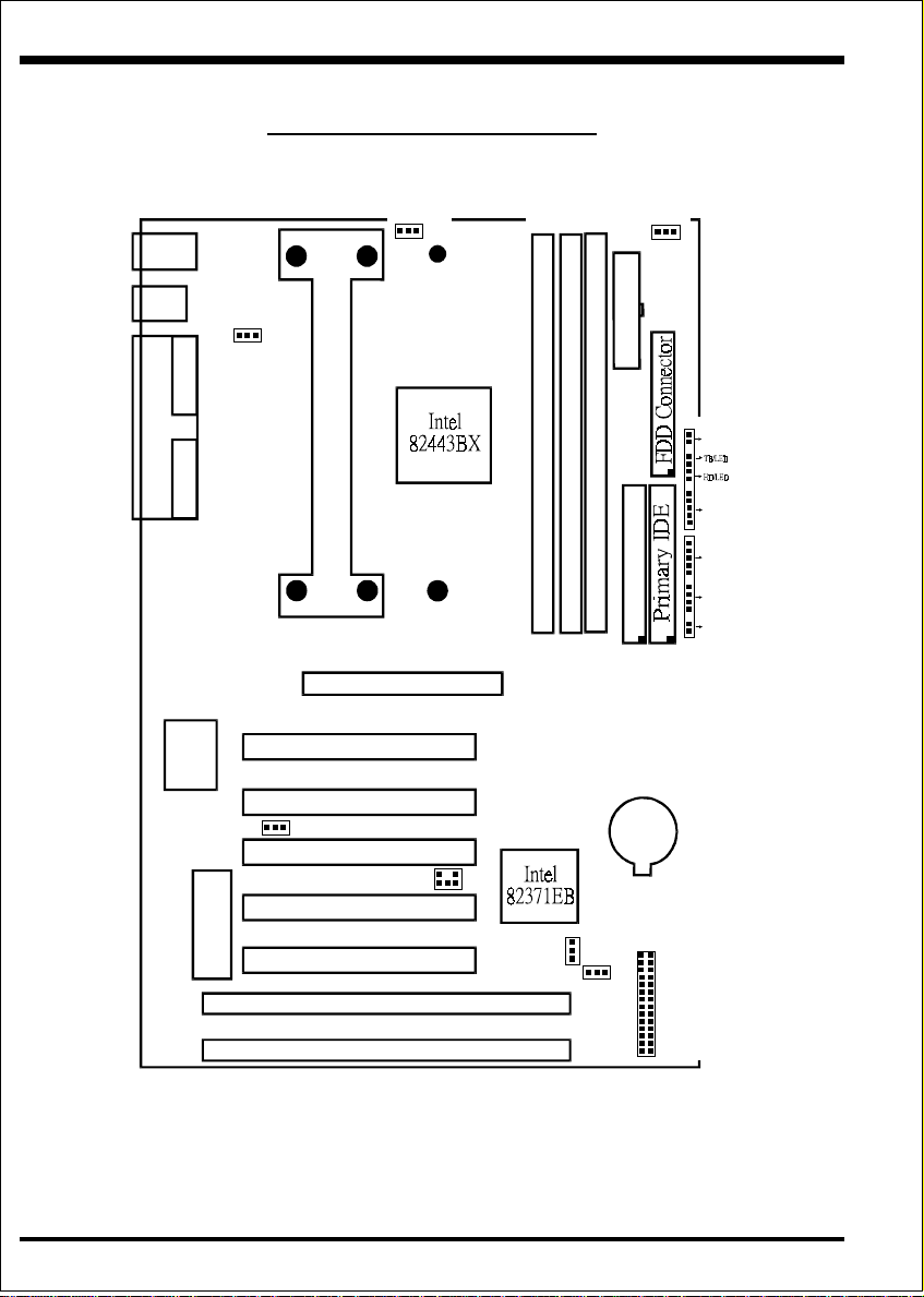
InstallationBX3
BX3 Detailed Layout
PS/2
USB
POWER
FAN
Bank 2
J5
ATX Power Input
USB 1
(Top)
USB 0
(Bottom)
Mouse
(Top)
Keyboard
(Bottom)
JP13
CPU FAN
J4
Bank 0
Bank 1
COM 1COM 2COM 2
J3
POWER_ON
+
Parallel Port
DIMM 1
CPU Cartridge SLOT 1
DIMM 2
FDD1
+
DIMM 3
IDE2
IR CONN.
1
5
KEYLOCK
1
SPK
Secondary IDE
RESET
J2
IDE1
AGP SLOT
PCI Slot #1
I/Oset
83977
Winbond
PCI Slot #2
J7:WOL
PCI Slot #3
SB_Link
J8
Battery
PCI Slot #4
J6
ESDJ
CHASSIS FAN
JP3
1 2
3.5X
4X
4.5X
5X
5.5X
6X
6.5X
7X
AUTO
66MHz
100MHz
110MHz
124MHz
133MHz
27 28
for BIOS
Flash M emory
PCI Slot #5
1
JP1
ISA Slot #1
ISA Slot #2
Page 3
Figure 1
Page 5

InstallationBX3
Easy Installation Procedure
Easy Installation Procedure
The following must be completed before powering on your new system:
Configure Jumpers to match your hardware
Install memory chips
Device Connectors
Configure Jumpers
We design this motherboard with the an ESDJ to make your install fast and easy.
The following will describe all of the ESDJ that you are required to set before moving
on to step 2.
Note: The ESDJ as depicted as shown (Figure 1) in their correct physical
orientation.
JP1 CM O S C lear
1
JP1 = 1-2 - Run Mod e (Default)
= 2 -3 - Clear C M O S (momen ta rily)
JP13
3
1
K eyboard Pow er-ON function (refer the section 3-5)
JP13 = 1-2 - Enabled
3
= 2 -3 - Disab led
(D efau lt)
J7 W O L (Wakup O n Lan) C onnector
R eserved for N IC (Netw ork Interface Ca rd) to
Wake the System.
J8 SB-LINK Header
Reserved for Creative SB-LINK (Sound Blaster
TM
L INK ) w ith th e So u n d Blast er AWE 6 4 D P C I
TM
Sound Card to C ompatible D OS games and
Mu ltim e d ia ap p lic at io n s.
Page 4
Page 6

InstallationBX3
Bus Clock
Multiplier
3.5X 233MHz 350MHz 385MHz* 434MHz* 466MHz*
4X 266MHz 400MHz 440MHz* 496MHz* 533MHz*
4.5X 300MHz 450MHz 495MHz* 558MHz* 600MHz*
5X 333MHz 500MHz 550MHz* 620MHz* *
5.5X 366MHz 550MHz 605MHz* * *
6X 400MHz* 600MHz* 660MHz* * *
6.5X * 650MHz* * * *
7X * 700MHz* * * *
AUTO Note 1
AGP Bus
Clock
PCI Bus
**
Note 1: AUTO : CPU Bus Clock Selection by CPU for Pentium® II/III Processor is 100MHz and the other is 66MHz
* : RSD (Reserved)
** : ESDJ (Easy-Setting-Dual-Jumper)
Clock
66MHz 100MHz 110MHz 124MHz 133MHz
66MHz 66MHz 73.3MHz* 82.6MHz* 89MHz*
33MHz 33MHz 36.6MHz* 31MHz* 33.3MHz*
CPU Selection
Note: Based on the implementation of Intel 440BX PCIset, BX3 is able to
provide two host bus frequencies -- either 66 or 100MHz for Slot1 processor and
memory operating. The default is set at 100MHz once Pentium® II processor to
be mounted onto this motherboard. However, no matter what kind of Slot1 processor you installed, it should come with right memory modules for normal and stable
operation. For example, if you install a Pentium® III processor, you should use
the SDRAM module with 100MHz based(or above) to match the CPU speed.
Furthermore, one thing you may need to bear in mind, before the CPU installation, it
is anyway our advice to use JP3 and set up right speed of Slot1 processor at any
time.
Page 5
Page 7

InstallationBX3
System Memory Configuration
Memory Layout
The BX3 supports (3) 168-pin DIMMs (Dual In-line Memory Module). The
DIMMs can be either EDO (Extended Data Out) or SDRAM (Synchronized
DRAM). The DIMMs may be installed using just one chip.
• We recommend using SDRAM DIMM can not mixing
with EDO DIMM modules.
• The EDO DIMM only support pentium
support Pentium III Processor at 100MHz.
• W e recommend when installed the 100MHz Pentium III Processor
using DIMM SDRAM must be 125MHz (-8ns) bus speed. If used
100MHz (-10ns) SDRAM may be critical timing for the
motherboard.
• About the “PC/100 SDRAM spec.” information you may visit Intel’s
home page at:
http//developer.intel.com/design/pcisets/memory/index.htm
• DIMM SDRAM may be 83MHz (-12ns), 100MHz (-10ns) or
125MHz (-8ns) bus speed.
Figure 2 and T able 1 show several possible memory configurations using
®
II Processor at 66MHz, not
DIMM 1 (M1)
DIMM 2 (M2)
DIMM 3 (M3)
Figure 2
Bank 0
Bank 1
Bank 2
-Synchronous
-S D R AM or ED O
DIM M
Page 6
Page 8

InstallationBX3
yromeMlatoT
BM867=
mumixaM
BM215=
mumixaM
BM652=
mumixaM
1X
1X
1X
1MMID
)0knaB(
*MARDS/ODE
,BM23,BM61,BM8
BM652,BM821,BM46
1X
*MARDS/ODE
,BM23,BM61,BM8
BM652,BM821,BM46
1X
*MARDS/ODE
,BM23,BM61,BM8
enoNenoN
BM652,BM821,BM46
2MMID
)1knaB(
*MARDS/ODE
,BM23,BM61,BM8
BM652,BM821,BM46
1X
*MARDS/ODE
,BM23,BM61,BM8
enoN
BM652,BM821,BM46
3MMID
)2knaB(
*MARDS/ODE
,BM23,BM61,BM8
Table 1
* SDRAM only supports 8, 16, 32, 64, 128MB DIMM modules. 256MB only
supports Registered Synchronouts DRAM Memory Modules.
* EDO only supports Pentium® II Processor at 66MHz, not supports Pentium III
Processor at 100MHz.
BM652,BM821,BM46
Page 7
Page 9

Device Connectors (continued)
InstallationBX3
J2
J3 1
+
+
Reset - Closed to restart system.
1
Speaker - Connect to the system's speaker for beeping
1. Speaker 3. GND
2. N/C 4. GND
KeyLock - Keyboard lock switch & Power LED connector
1. Power LED(+) 4. Keylock
2. N/C 5. GND
3. GND
* The power LED lights when the
system is powered on and blinks in
SLEEP MODE (Suspend mode).
IR Connector
1. VCC 4. GND
2. NC 5. IRTX
3. IRRX
IDE LED indicator - LED ON when Onboard PCI IDE Hard disks is
activate
Turbo LED indicator - LED ON when higher speed is selected
Power On/Off - This is connected to the power button on the case.
Using the Soft-Off by Pwr-BTTN feature, you can choose either
Instant Off (turns system off
immediately), or 4 sec delay (you need to
hold the button down for 4 seconds before the system turns off). When
the system is in 4 sec delay mode, we has added a special feature to
make the system go into suspend mode when the button is pressed
momentarily.
Page 8
 Loading...