

Page 1
8KT
An An
AMD SocAMD Soc
An
AMD Soc
An An
AMD SocAMD Soc
based motherboard (133/100MHz)
SupporSuppor
Suppor
SupporSuppor
TRADEMARK
All products and company names are trademarks or registered
trademarks of their respective holders.
These specifications are subjected to change without notice.
ts PC-133 SDRAM Modulests PC-133 SDRAM Modules
ts PC-133 SDRAM Modules
ts PC-133 SDRAM Modulests PC-133 SDRAM Modules
AA
A
AA
kk
et et
A PrA Pr
k
et
A Pr
kk
et et
A PrA Pr
ocessorocessor
ocessor
ocessorocessor
Manual Revision 1.0
June 21, 2000
Page 2

FEA TURES
8KTA Features:
8KTA is based on the AMD Socket A Processors operating at 600
~ 1GHz on Socket A.
Designed with VIA KT133 AGPset.
Supports up to 768MB of DRAM (minimum of 32 MB) on board
8KTA will support Error Checking and Correcting (ECC) when using
parity SDRAM memory modules. This will detect multiple bit errors and
correct 1-bit memory errors.
Supports (1) 16 bit ISA slots, (6) 32 bit PCI slots, (1) 4X AGP slot and
provides (2) independent high performance PCI IDE interfaces capable of
supporting PIO Mode 3/4 and Ultra DMA 33/66 devices.
The 8KTA supports (6) PCI Bus Master slots and a jumperless PCI
INT# control scheme which reduces configuration confusion when plug
ging in PCI card(s).
Features8KTA
Supports ATAPI (e.g. CD-ROM) devices on both Primary and Secondary
IDE interfaces.
Designed with on chip Multi I/O: (1) floppy port, (1) parallel port (EPP,
ECP), and (2) serial ports (16550 Fast UART).
Note: Japanese Floppy 3 mode is also supported
Features Award Plug & Play BIOS. With Flash Memory you can always
upgrade to the current BIOS as they are released.
8KTA utilizes a Lithium battery which provides environmental
protection and longer battery life.
Page 2
Page 3

Features8KTA
4 USB ports provided, 2 ports are onboard and another 2 USB ports as optional.
Built-in ATX 20-pin power supply connector.
Software power-down when using Windows® 95/98 or Windows®2000.
Supports ring-in feature (remote power-on through external modem,
allows system to be turned on remotely).
Resume by Alarm - Allows your system to turn on at a preselected time.
Power Loss Recovery - In the event of a power outage your system will
automatically turn itself back on without user intervention.
Supports CPU Hardware sleep and SMM (System Management Mode).
Supports Keyboard power ON function (KBPO).
Built-in WOL (Wake-up On LAN) Connector.
Built-in AC97 PCI Audio.
Supports STR (Suspend to RAM) function.
Supports CPU Front Side Bus setting via BIOS.
Page 3
Page 4
Installation8KTA
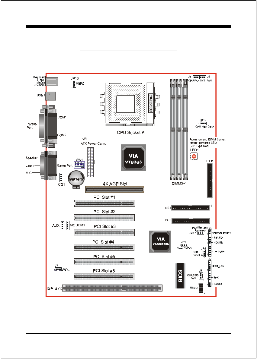
8KTA Detailed Layout
Page 4
Figure 1
Page 5

Installation8KTA
Easy Installation Procedure
The following must be completed before powering on your new system:
CPU Insertion
Jumper Settings
System memory Configuration
Device Connectors
CPU Insertion
CPU Insertion: (use AMD AthlonTM as reference)
Step 1
Open the socket by raising the actuation
lever.
Figure 2
Figure 3
Step 2
Insert the processor.
Ensure proper pin 1 orientation by aligning
the FC-PGA corner marking with the
socket corner closest to the actuation arm
tip. The pin field is keyed to prevent misoriented insertion.
Dont force processor into socket. If it does
not go in easily, check for mis-orientation and
debris.
Make sure the processor is fully inserted
into the socket on all sides.
Page 5
Page 6

Installation8KTA
Step 3
Close the socket by lowering and
locking the actuation lever.
Figure 4
Step 4
Thermal conductive and qualified heatsink recommended by AMD are a must to
avoid CPU overheat and burned.
Page 6
Figure 5
Page 7

Installation8KTA
Jumper Settings
The 8KTA motherboard was designed with very few jumpers to make your
installation faster and easier.
SW1: CPU Vcore Voltage Selection
ON
6
12345
SW1 Pin6
OFF = Vcore adjustable by switch
ON = Vcore auto detected
1234 5
FFOFFOFFOFFONO03.1
NOFFOFFOFFONO53.1
FFONOFFOFFONO04.1
NONOFFOFFONO54.1
FFOFFONOFFONO05.1
NOFFONOFFONO55.1
FFONONOFFONO06.1
NONONOFFONO56.1
FFOFFOFFONONO07.1
NOFFOFFONONO57.1
FFONOFFONONO08.1
NONOFFONONO58.1
FFOFFONONONO09.1
NOFFONONONO59.1
FFONONONONO00.2
NONONONONO50.2
*Note: any Vcore setting over CPU specification
may cause CPU to be burned.
JP1 CMOS Clear
1
JP1 = 1-2 Normal (Default)
= 2-3 Clear CMOS
1WS
erocVUPC
)V(
JP2 STR Function
1
JP2 = 1-2 Disabled
= 2-3 Enabled
Page 7
Page 8

Installation8KTA
JP3 Power Loss Recovery
1
JP3 = 1-2 Disabled
= 2-3 Enabled
JP13 Keyboard Power-ON Function
1
JP13= 1-2 Disabled (Default)
= 2-3 Enabled
JP14 CPU Host Clock Select
1
JP14= 1-2 100MHz
= 2-3 133MHz
Page 8
Page 9

Installation8KTA
System Memory Configuration
Memory Layout
The 8KTA supports (3) PC133 168-pin DIMMs (Dual In-line Memory
Module). The DIMMs is for SDRAM (Synchronous DRAM) only.
DIMM SDRAM may be 83MHz (12ns), 100MHz (10ns) or
125MHz (8ns) bus speed.
If you use both 50ns and 60ns memory you must configure
your BIOS to read 60ns.
When using Synchronous DRAM we recommend using the
4 clock variety over the 2 clock.
Figure 2 and Table 1 show several possible memory configurations.
DIMM 1
DIMM 2
DIMM 3
Bank 0/1
Bank 2/3
Bank 4/5
Synchronous
DRAM
Figure 2
yromeMlatoT
BM652=
mumixaM
BM215=
mumixaM
BM867=
mumixaM
1MMID
)1/0knaB(
*MARDS
1XBM652
*MARDS
1XBM652
*MARDS
1XBM652
,BM821,BM46,BM23
,BM821,BM46,BM23
,BM821,BM46,BM23
enoNenoN
2MMID
)3/2knaB(
*MARDS
,BM46,BM23
1XBM652,BM821
*MARDS
,BM821,BM46,BM23
1XBM652
enoN
3MMID
)5/4knaB(
*MARDS
,BM821,BM46,BM23
1XBM652
Table 1
* SDRAM only supports 32, 64, 128, 256MB DIMM modules.
* We recommend to use PC100 Memory Module for bus speed 100MHz and
PC133 Memory for bus speed over 100MHz.
* Using non-compliant memory with higher bus speed (over clocking) may
severely compromise the integrity of the system.
Page 9
Page 10

Device Connectors
Installation8KTA
parallel port
PS/2 Mouse
PS/2
KEYBOARD
J2,J3: Chassis Panel Connector
Power_LED, Speaker, Reset, Sleep, Turbo LED and HDD LED
J4: CPU Fan Power
A plug-in for the CPU Fan Power
J5: SYS Fan Power
A plug-in for the Power Supply Fan Power
J6: Chassis Fan Power
A plug-in for the chassis Fan Power
J7:WOL (Wake On LAN) Connector
USB port
COM1
Figure 7
COM2
Joystic/Midi
Speaker
Line_in
MIC
IDE1: Primary IDE Connector (White Color)
IDE2: Secondary IDE Connector (Black Color)
FDD1: Floppy Controller Connector (Black Color)
PW1: ATX Power Connector
20-pin power connector
CD1: CD Audio_IN Connector
Pin1(CD_IN_Left), Pin2/Pin3(CD_Reference), Pin4(CD_IN_Right)
Page 10
Page 11

Installation8KTA
AUX1: Auxiliary Line_IN Connector
Pin1(Left Line_IN), Pin2/Pin3(GND), Pin4(Right Line-IN)
MODEM1: Telephony Connector
Pin1(Audio_in), Pin2/Pin3(GND), Pin4(Mic-out to Modem)
USB2: USB port header pins for adding two additional USB ports.
VCC
-Data
+Data
GND
1
5
6
GND
+Data
-Data
VCC
10
USB port header pin descriptions.
#NIProloceriWemaNlangiStnemmoC
1deRccVrewoPelbaC
2etihWataD-ataD
3neerGataD+ataD
4kcalBdnuorGdnuorGelbaC
5kcalBdnuorGdnuorGesaC
6kcalBdnuorGdnuorGesaC
7kcalBdnuorGdnuorGelbaC
8neerGataD+ataD
9etihWataD-ataD
01deRccVrewoPelbaC
Page 11
Page 12

Device Connectors (continued)
(This is connected to the power button on the case. Using the Soft-Off
by Pwr-BTTN feature, you can choose either Instant Off (turns system
off immediately), or 4 sec delay (you need to hold the button down for
4 seconds before the system turns off). When the system is in 4 sec
delay mode, there is a special feature to make the system to go into
suspend mode when the button is pressed momentarily).
J3
+
+
Power On/Off
1
Turbo LED indicator - LED ON when higher speed is selected
IDE LED indicator - LED ON when Onboard PCI IDE Hard disks
is activate
IR Connector
1. VCC 4. GND
2. NC 5. IRTX
3. IRRX
1
Installation8KTA
J2
Power LED - Power LED connector
1. Power LED(+) 4. NC
2. N/C 5. GND
3. GND
1
Speaker -
Connect to the system's speaker for beeping
1. Speaker 3. GND
2. N/C 4. GND
1
Reset - Closed to restart system.
1
Page 12
 Loading...