

Page 1

6WEA4I
®®
®
A PA P
entiumentium
A P
entium
A PA P
entiumentium
PrPr
ocessor based ocessor based
Pr
ocessor based
PrPr
ocessor based ocessor based
(133/100/66MHz)(133/100/66MHz)
(133/100/66MHz)
(133/100/66MHz)(133/100/66MHz)
TRADEMARK
All products and company names are trademarks or registered
trademarks of their respective holders.
These specifications are subjected to change without notice.
®®
II or P II or P
II or P
II or P II or P
Manual Revision 1.0
November 23, 1999
entiumentium
entium
entiumentium
AA
GPGP
A
GP
AA
GGP
®®
®
®®
III Slot1 III Slot1
III Slot1
III Slot1 III Slot1
motherboard
Page 2

Features6WEA4I
FEATURES
6WEA4I Features:
• 6WEA4I is based on the Pentium® II or Pentium® III Processor operating at 350 ~ 733MHz (100/133MHz) on Slot 1. The board is configured
by a BIOS setting to match your CPU clock speed.
• Designed with Intel’s 810E chipset.
• Supports up to 512 MB of DRAM (minimum of 16 MB) on board, You
can use 168-pin DIMM x 2. It will run Synchronous DRAM memory
(SDRAM) at 100MHz.
• 64-bit system memory interface with optimized support for SDRAM at
100MHz.
• Integrated 2D & 3D Graphics Engine, H/W Motion Compensation Engine,
230MHz DAC and 4MB Display Cache.
• AC’97 2.1 Audio CODEC onboard for enables the software Audio.
• Supports (5) 32 bit PCI slots, provides (2) independent high performance
PCI IDE interfaces capable of supporting PIO Mode 3/4 and Ultra DMA
66 devices. The 6WEA4I supports (5) PCI Bus Master slots and a
jumperless PCI INT# control scheme which reduces configuration confusion when plugging in PCI card(s).
• Supports ATAPI (e.g. CD-ROM) devices on both Primary and Secondary
IDE interfaces.
• Designed with Winbond W83627HF LPC (Low Pin Count) I/O: (1) floppy
port, (1) parallel port (EPP, ECP), and (2) serial ports (16550 Fast UART)
• Includes a PS/2 mouse connector.
• Allows use of a PS/2 keyboard.
• Features Award Plug & Play BIOS. With 4MB(FWH) Flash Memory you
can always upgrade to the current BIOS.
Page 2
Page 3

Features 6WEA4I
• 6WEA4I utilizes a Lithium battery which provides environmental
protection and longer battery life.
• Supports the Universal Serial Bus (USB) connector. The onboard ICH
(82801AA) chip provides the means for connecting PC peripherals such
as; keyboards, joysticks, speaker, and mouse.
• Built-in ATX 20-pin power supply connector.
• Software power-down when using Windows® 95/98.
• Supports ring-in feature (remote power-on through external modem, allow
system to be turned on remotely.
• Resume by Alarm - Allow your system to turn on at a preselected time.
• Supports CPU Hardware sleep and SMM (System Management Mode).
• Supports Hot key, Any key or password Keyboard power ON function
(KBPO).
• Supports the CPU, PWR and Chassis fan Auto stop in the sleep mode.
• Supports the System Power LED (PANEL) blinks in the sleep mode.
• Built-in WOL (Wake On Lan) Connector.
• Supports the AMR Connector for enables the software modem.
• Y2K Compliant.
• Advanced Configuration Power Interface (ACPI) ready.
• Supports USDM software to offer motherboard various status on Windows
95/98.
• Supports the STR (Suspend To RAM) power management by ACPI’s S3.
• Supports the STR indicator red LED (D23) to avoid pluging or un-pluging
DIMM modules when in a STR mode or power on mode.
• Supports ISA Slot.
Page 3
®
Page 4
Installation 6WEA4I
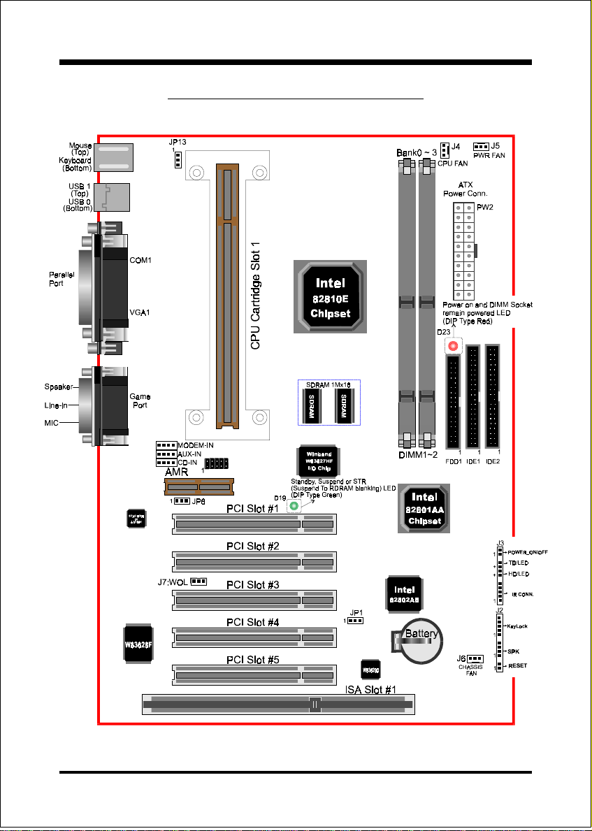
6WEA4I Detailed Layout
Page 4
Figure 1
Page 5

Installation6WEA4I
Easy Installation Procedure
Easy Installation Procedure
The following must be completed before powering on your new system:
Configure Jumpers to match your hardware
System Memory Configuration
Device Connectors
Configure Jumpers
We design this motherboard with the a few jumpers to make your installation fast
and easy.
The following will describe all of the jumpers that you are required to set.
JP1 CMOS Clear
1
JP1 = 1-2 Normal (Default)
= 2-3 Clear CMOS
JP13
1
Keyboard Power-ON Function
JP13= 1-2 Enabled
= 2-3 Disabled (Default)
Page 5
Page 6

Installation 6WEA4I
JP8
1
On Board AC’97 Codec Audio
JP8=1-2 Enabled (Default for 6WEA4I)
= 2-3 Disabled
AC’97/MR Configuration T able
8PJI4AEW6/4AEW6-PE
2-1
3-2
* Audio Codec’97 (AC’97)
** Audio Codec (AC)
** * Modem Codec (MC)
**** Audio/Modem Codec (AMC)
***** Modem Riser Card (MR)
Note: In the BIOS setting, “AC97 Audio” of “Integrated Peripher-
als” must be changed from “Enabled” to “Disabled” as well to
come with JP8 setting (at “2-3” position). (refer to page 4-14).
)yramirP(draobnO79'CA
)yradnoceS(CMroRM
79'CAdraobnOdelbasiD
)yramirP(CMAroCMroRM
Page 6
Page 7

Installation6WEA4I
System Memory Configuration
Memory Layout
The 6WEA4I supports (2) 168-pin DIMMs (Dual In-line Memory Module).
The DIMMs can be either EDO (Extended Data Out) or SDRAM (Synchronized
DRAM).
• 100MHz system memory bus frequency. Even if the system host bus is
66MHz.
• 8MB to 256MB using 16MB/64MB technology (512MB using 128MB
technology).
• 256MB Support Registered synchronous DRAM Memory Modules.
• We recommend to installed the “PC/100MHz SDRAM Spec.”, using
DIMM SDRAM must be 125MHz (-8ns) bus speed. If used 100MHz
(-10ns) SDRAM may be critical timing for the motherboard.
• DIMM SDRAM may be 100MHz (-10ns) or 125MHz (-8ns) bus speed.
Figure 2 and Table 1 show several possible memory configurations using
enoN
Bank 2/3
Bank 0/1
2MMID
*MARDS
-Synchronous
)3/2knaB(
,BM46,BM23,BM61
1XBM652,BM821
DIMM 2
DIMM 1
yromeMlatoT
BM652=
mumixaM
BM215=
mumixaM
Figure 2
1MMID
)1/0knaB(
*MARDS
,BM46,BM23,BM61
1XBM652,BM821
*MARDS
,BM46,BM23,BM61
1XBM652,BM821
* SDRAM only supports 16, 32, 64, 128, 256MB DIMM modules.
Table 1
Page 7
Page 8

Installation6WEA4I
Device Connectors
Please install the motherboard into the chassis.
Now that your motherboard is installed you are ready to connect all your connections (figure 7).
parallel port
Joystick/Midi
PS/2 Mouse
PS/2
KEYBOARD
J2,J3: Chassis Panel Connector
• Keylock, Speaker, Reset, Sleep, Turbo LED and HDD LED
J4: CPU Fan Power
• A plug-in for the CPU Fan Power
J5: Power Supply Fan Monitoring
• A plug-in for the Power supply so that BIOS can monitor the RPM’s
J6: Chassis Fan Power
• A plug-in for the chassis Fan Power
J7: WOL (Wake On Lan) Connector
PW2: ATX Power Connector
• 20-pin power connector
IDE1: Primary IDE Connector
IDE2: Secondary IDE Connector
FDD1: Floppy Controller Connector
CD-IN: CD Audio_IN Connector
• Pin1(CD_IN_Left), Pin2/Pin3(GND), Pin4(CD_IN_Right)
AUX_IN: Auxiliary Line_IN Connector
• Pin1(Left Line_IN), Pin2/Pin3(GND), Pin4(Right Line-IN)
MODEM_IN: Telephony Connector
• Pin1(Audio_in), Pin2/Pin3(GND), Pin4(Mic-out to Modem)
USB port
COM1 VGA1
Figure 7
Speaker
Line_in
MIC
Page 8
Page 9

Installation 6WEA4I
Device Connectors (continued)
Power On/Off
(This is connected to the power button on the case. Using the SoftOff by Pwr-BTTN feature, you can choose either Instant Off (turns
immediately), or 4 sec delay (you need to hold the button
1. VCC 4. GND
2. NC 5. IRTX
3. IRRX
J3
system off
down for 4 seconds before the system turns off). When the system is
in 4 sec delay mode, there is a special feature to make the system to
go into suspend mode when the button is pressed momentarily.)
1
Turbo LED indicator - LED ON when higher speed is selected
+
IDE LED indicator - LED ON when Onboard PCI IDE Hard disks
+
is activate
IR Connector
1
J2
Page 9
KeyLock - Keyboard lock switch & Power LED connector
1. Power LED(+) 4. KeyLock
1
Speaker -
2. N/C 5. GND
3. GND
Connect to the system's speaker for beeping
1. Speaker 3. GND
2. N/C 4. GND
* The power LED lights when the
system is powered on and blinks in
SLEEP MODE (Suspend mode).
1
Reset - Closed to restart system.
1
 Loading...