

Page 1
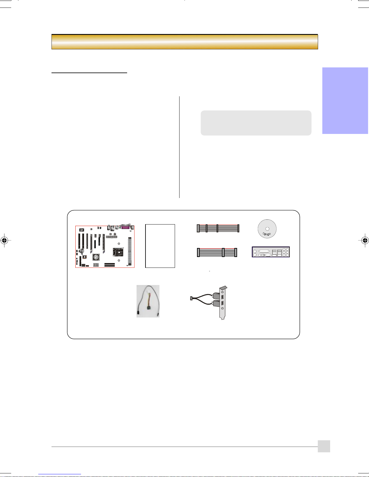
1-1 Package Contents
Introduction
Section 1 -- Introduction
Contents
A. Mainboard
B. User’s manual
C. Floppy drive cable
D. HDD drive cable
E. CD (drivers and utilities)
F. I/O Shield
G. SATA II data and power cable
USER’S
MANUAL
Optional items
H. Extra USB2.0 port cable
English
If you need the optional item, please
contact your dealer for assistance.
E
C
A
G
D
F
B
H
1
Page 2

Introduction
1-2 Mainboard Features
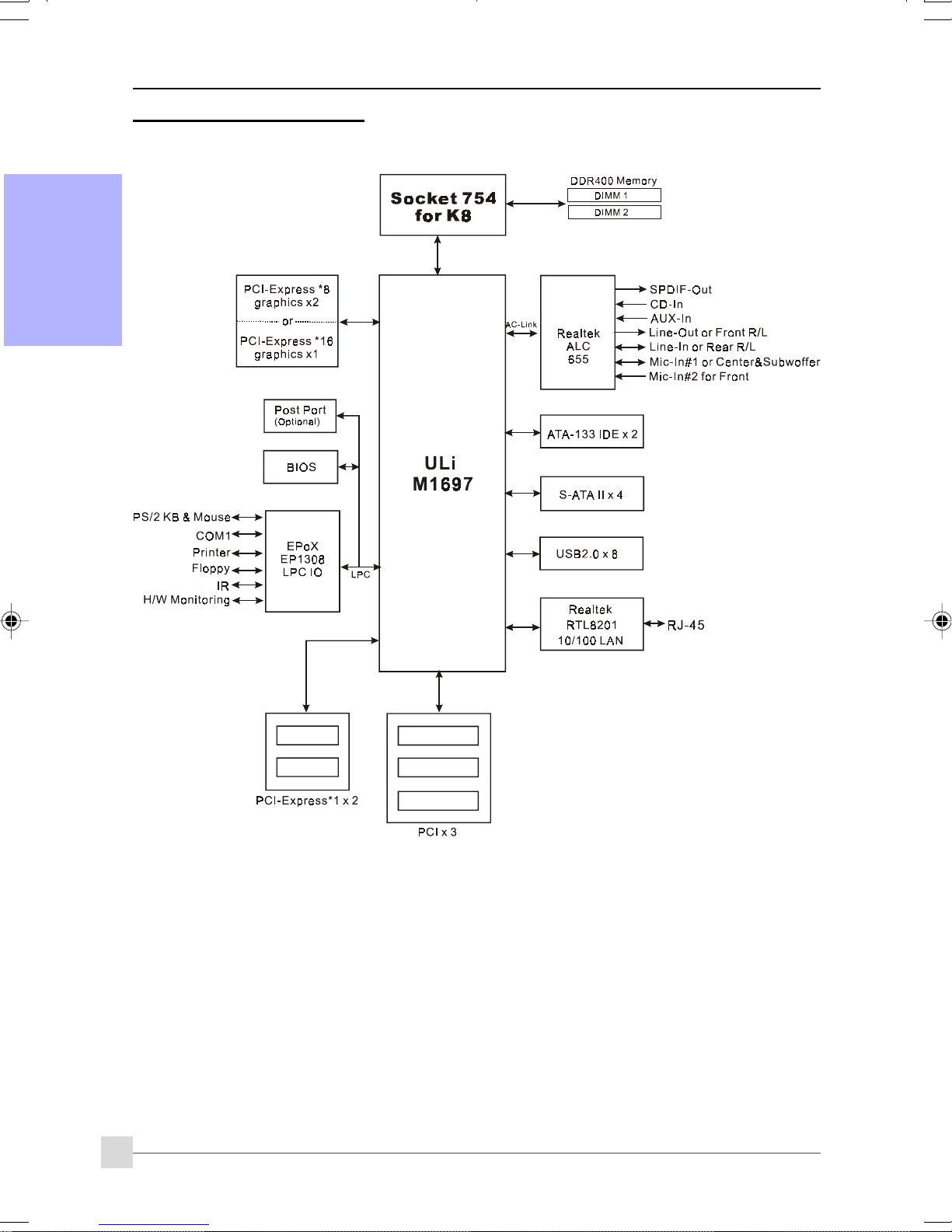
Socket 754
English
Socket 754-based motherboards are designed to provide performance enhancements for AMD
Sempron/Athlon 64 processor-based systems, and it also expected to be the next-generation
of platform innovations.
For more information about all the new features Athlon
website at
http://www.amd.com
Chipset
The board is designed with ULi M1697 chipset, featuring performance and stability with the
most innovative technology and features.
For more details about the ULi chipset, please visit the ULi Web site at
GLI mode (Graphics Link Interface)
GLI mode allows two PCI-Express VGA cards to be installed on the same mainboard to enjoy
dual display experience. With this technology you can expand your desktop space across two
monitors and have independent display on each monitor.
PCI-Express (PCI-E)
Next generation peripheral interface to succeed to current PCI bus for the next decade. With
smaller slot size and 250MB/sec (PCI-E*1) or 4GB/sec(PCI-E*16) maximum transfer, PCI-Express
overcomes PCI bus bottleneck.
Brief Introduction
TM
Processor deliver, check out the AMD
http://www.ULi.com.tw.
Jumper Configurable PCI-Express
This mainboard is cleverly designed with a jumper configurable PCI-Express slot that lets user
select the single or dual VGA support.
Hardware Monitoring
Hardware monitoring enables you to monitor various aspects of the system operation and
status. This includes CPU temperature, voltage and fan speed in RPMs.
10/100 LAN
This mainboard is mounted with a 10/100BASE-T Ethernet LAN controller. It allows the mainboard
to connect to a local area network by means of a network hub.
Serial ATA II
S-ATA II is the second generation SATA interface with double the transferring speed up to
300MB/sec. It supports NCQ to provide faster reading speed for your storage devices.
SATA RAID
RAID function available on chipset’s SATA II ports, RAID 0, 1, 0+1, 5, JBOD by ULi driver support.
USB2.0
A popular USB standard for plugging in peripherals with up to 480Mbps transfer speed while
maintaining backward compatibility with older USB1.1 device.
6ch
Mainboard is equipped with 6 channel of audio to support Dolby Digital 5.1 audio for DVD-playback.
The onboard audio jacks can be configured for normal 2 channel mode or 6 channel mode.
AMD Cool'n'QuietTM Technology
AMD's Cool'n'Quiet
TM
Technology lowers CPU operating voltage when the system is in idle mode.
This helps to reduce heat dissipation and in effect lowers the fan speed to noise from your PC.
2
Page 3

Special Features
BIOS Features:
Ghost BIOS
No more worries if BIOS gets corrupted causing your system unable to boot. The onboard
backup BIOS will rescue & recover main BIOS in just a few easy steps.
Thunder Probe
A hardware diagnostic software to monitor voltage, temperature and speed of a variety of
hardware. It also includes an ingenious built in fan control feature called Smart Fan.
Thunder Flash
A Windows based innovation tool to provide safe and easy BIOS rescue function, BIOS flash
function and personal start up screen.
Magic Health
Reports your system hardware status for every boot-up to help detect faults early. Monitor
hardware status including CPU temperature, CPU/Memory/Chipset voltage, fan RPM speed for
chassis fan, CPU fan & Power supply fan.
Introduction
English
EZ-Boot
Simply press “ESC” to select your bootable device. No more hassle to search the BIOS menu,
change and re-start.
PowerBIOS
Supporting a full range of overclocking setting via BIOS. Various adjustable feature include FSB/
Memory/Chipset voltage tweaking.
H/W Features:
Post Port (Optional)
An onboard LED-display trouble-shooting device, facilitating user to detect boot-up problems.
QuickSPDIF
On board SPDIF-out connector for quick connection to multi-channel speakers. Not only
removes cable cluttering but also delivers loss-free digital audio to let you enjoy DVD movies and
games with crystal clear sound.
EZ-Button (Optional)
A handy power-on button located onboard to turn on/off the system easily, especially while
debugging or testing the system.
3
Page 4
Introduction
1-3 System Block Diagram
English
4
Page 5
Introduction
1-4 Mainboard Specification
Processor
Support Socket-754 based AMD Sempron/Athlon-64 up to 3700+ with 1.6GTs Hyper
Transport processors
Chipset
ULi M1697 Chipset
Main Memory
Two 184-pin DDR SDRAM DIMM sockets
Support single-sided or double-sided 2.5v DDR-333/400 DIMMs in 128/256/512Mb technologies
Supports up to 2GB memory size
Expansion Slots
Three PCI connectors compliant with PCI v2.3
Two PCI-Express (x1) connectors compliant with PCI Express 1.0a
Two PCI-Express (x16) connectors compliant with PCI Express 1.0a
USB
Eight USB connectors compliant with USB2.0 from embedded USB controller (4 connectors
at rear panel)
English
LAN
One 10/100 Ethernet from Realtek RTL8201 LAN PHY
P-ATA IDE
Two IDE interface (up to 4 IDE devices) with UDMA-33/66/100/133 support from embedded
IDE controller
S-ATA RAID
Four S-ATA II ports with up to 300MB/s bandwidth with RAID 0, 1, 0+1, 5
I/O
Onboard EPoX EP1308 LPC bus I/O controller
Legacy peripheral interface for PS/2 keyboard & mouse, FDD, Parallel, Serial, and IrDA (v1.0
compliant)
Support Hardware Monitoring for fan speed monitoring and CPU temperature sensing
Audio
6 channel audio from onboard Realtek ALC655 AC’97 v2.3 compliant CODEC
- Support CD-In, AUX-In
- Support Jack detection for fool-proof audio device installation
- Rear panel audio jacks configuration
roloCkcaJoiduA
eulBthgiLni-eniLtuo-oeretsraeR
emiLtuo-eniLtuo-oeretstnorF
kniPni-ciMrefoowbuS&retneC
lennahc2 lennahc6
5
Page 6

Introduction
English
BIOS
Flash EEPROM with Award Plug&Play BIOS
Support EZ Boot for fast bootable device selection
Support Magic Health for system hardware status report during system boot-up
Support Ghost BIOS for BIOS Recovery
Peripheral Interfaces
))
) At Rear Panel
))
PS/2 keyboard and mouse ports
One Parallel (printer) port
One S/PDIF-Out Coaxial jack
One Serial port
One RJ45 LAN connector
Four USB2.0 ports
Three Audio jacks
))
) Onboard connector and pin-header
))
One floppy drive connector
Two ATA-100/133 IDE connectors
Four extra USB2.0 ports
One CD-IN and AUX-IN connectors
One IR connector
Four S-ATA II connectors
Three Fan connectors
Front Panel Controller
Supports Reset & Soft-Off switches
Supports HDD & Power LEDs
Supports PC speaker
Supports Front Panel Audio connector
Special Features
Support KBPO function – Keyboard power on, turn on the computer from keyboard
Support Wake-On-LAN by PME
Onboard Post Port LED display for system debugging (Optional)
PowerBIOS for excellent overclocking features:
- Programmable FSB Clock output frequency with 1MHz fine tuning
- Support BIOS adjustable CPU multiplier, FSB clock, DIMM frequency
- Support BIOS adjustable CPU Core voltage, Chipset voltage and DIMM voltage
Support EZ-Button – A handy power-on button onboard to turn on/off the system easily
(Optional)
Support Ghost BIOS - Rescue, recover BIOS in an easy step and no more worry of BIOS
being corrupted.
6
Page 7

Introduction
Powerful utilities for Windows
Support Thunder Probe - A hardware diagnostic software to monitor voltage, temperature
and speed of a variety of hardware. It also includes an ingenious built in fan control feature
called Smart Fan.
Support Thunder Flash - A Windows based innovation tool to provide safe and easy BIOS
rescue function, BIOS flash function and personal start up screen.
Form Factor
305mm x 220 mm ATX size
Depending on the model you purchased, some components are optional and may
not be available.
English
7
Page 8
Introduction
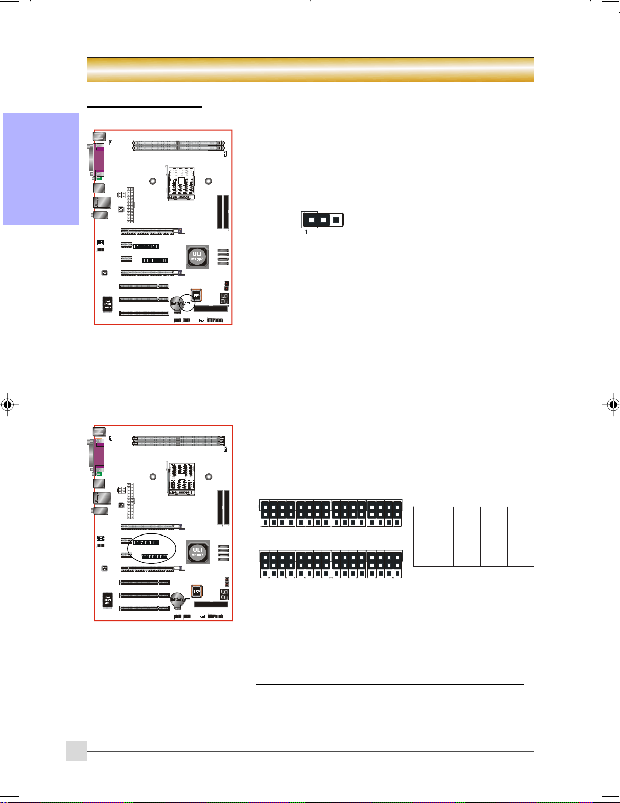
2-1 Jumper Settings
Section 2 -- Installation
English
JCMOS: Clear CMOS data Jumper
If the CMOS data becomes corrupted or you forgot the
supervisor or user password, clear the CMOS data to
reconfigure the system back to the default values stored in
the ROM BIOS.
Settings:
1-2: Normal (Default)
2-3: Clear CMOS
To CMOS Clear data, please follow the steps below.
1. Turn off the system.
2. Change the jumper from “1-2” to “2-3” position
for a few seconds.
3. Replace the jumper back to the “1-2” position.
4. Turn on the system and hold down the <Del> key
to enter BIOS setup.
JPE1~JPE8: PCI-E slot Control Jumper
This mainboard is cleverly designed with a jumper configurable
PCI-Express slot that lets user select the x16 bandwidth for
single VGA mode or x8 bandwidth for dual VGA mode.
JPE1
1
JPE2 JPE6
1
Set all jumpers to 1-2 to use PE1 as high bandwidth PCI-E x16 slot.
Set all jumpers to 2-3 to use PE1 and PE4 as bandwidth PCI-E x8
slot for GLI mode.
Jumpers JPE1 to JPE8 must always be set to the same
mode.
JPE3
JPE5 JPE7
JPE8JPE4
8EPJ~1EPJ
1EP4EPedoM
sgnitteS
2-1
3-28x8xiLG
61xenoN
)tluafeD(
elgniS
AGV
8
Page 9

2-2 System Memory Configuration
The mainboard accommodates two PC2700/PC3200 184-pin DIMMs.
• Supports up to 2.0GB of 333/400MHz DDR SDRAM.
• Supports unbuffered DIMM configurations defined in JEDEC DDR DIMM specification.
Memory configurations supported:
oNtolSMMID1sMMID2
1#MMIDSS/SDSS/SD
2#MMIDSS/SDSS/SD
* SS: Single-Sided DIMM, DS: Double-Sided DIMM
Memory Installation :
To install, align the notch on the DIMM module with the connector.
Press straight down as shown in the figure until the white clips close and the module fits
tightly into the DIMM socket.
Introduction
English
Notch
9
Page 10

Introduction
2-3 Rear IO Port
The I/O back panel for this mainboard is shown below. When installing the mainboard into the
computer case, use the bundled I/O shield to protect this back panel.
English
PS/2
Mouse
PS/2
Keyboard
S/PDIF-out
Coaxial Jack
2-4 Internal Connectors
Parallel Port
1
4
COM
RJ45
LAN
USB2.0 x 4 ports
Line-in/Rear out (Light Blue)
Line-out/Front out (Lime)
Mic-in/Center&Subwoofer (Pink)
1
10
3
6
5
9
10
11
2
7
1
8
Page 11

Connectors Figure Descriptions
Introduction
JCPU_FAN
1
JPWR_FAN
JSYS_FAN
FDD
2
IDE1
3
Primary IDE
IDE2
Secondary IDE
1
Ground
1
+12V
Sense
CPU / Power / Chassis Fan Power Connectors
JCPU_FAN: Connect the CPU fan to this
connector.
JPWR_FAN: Use this connector if you are installing
an additional fan in the unit.
JSYS_ FAN: The chassis fan will provide adequate
airflow throughout the chassis to
prevent overheating the CPU.
Floppy Drive Connector
Primary/Secondary IDE Connector
Connects to the IDE device, i.e. HDD and CD-ROM
device.
When using two IDE drives on the same
connector, one must be set to Master mode
and the other to Slave mode. Refer to your
disk drive user’s manual for details.
English
4
5
6
PW1
PW12
CFPA
CD-IN
AUX-IN
4
3
2
1
MIC_In
NC
Front Line-out-R
Front Line-out-L
23
24
3.3V
+12V
+12V
+12V+12V
GroundGround
2
1
10
9
CD_IN_Right
CD_Reference
CD_IN_Left
1
AUX_IN_Right
GND
AUX_IN_Left
1
Ground
+5V
+5V
+5V5VSB
-5VPW-OK
GroundGround
Ground+5V
GroundGround
PS-ON+5V
GroundGround
-12V3.3V
3.3V3.3V
11
1
GND
+5V
Rear Line-out-FR
Key
Rear Line-out-FL
PW1: 24-pin ATX Power Connector
PW12: 4-pin ATX12V Power Connector
The plugs of the power cables are designed to fit in
only one orientation.
The PW1 and PW12 Power Connector must
be used simultaneously.
CFPA: Front Panel Audio Connector
This connector is used only if the speaker and microphone needs to be plugged at the front of the PC case.
Otherwise, leave the jumpers at the default position.
CD-IN/AUX-IN: CD Audio-in connectors
These connectors are used to receive audio from a CDROM drive, TV tuner or MPEG card.
11
Page 12

Introduction
7
English
8
Connectors Figure Descriptions
CUSB3/CUSB4: Four USB2.0 header
CUSB3
CUSB4
CFP
This mainboard includes 4 additional onboard USB ports.
To use these additional USB ports, a USB bracket is
required. Please contact your retailer for details.
CFP: Case Front Panel Connector
HD_LED
This LED indicates hard drive activity.
PWR_LED
Connects to the power indicator on the PC case.
RST
Connects to the RESET switch on the PC case.
PW_ON
Connects to the Power button on the PC case, to
turn on the system. To turn off the system,
press the power button for 4 seconds.
9
10
11
CIR
CSPK
SATA1
SATA2
SATA3
SATA4
EZ-Button
(Optional)
CP80P
(Optional)
GND
CIR: IR connector
For connection to an IrDA receiver unit.
CSPK: Speaker
Connects to the case’s speaker for PC beeps.
1
B+
GND
GND
A+
A-B-
SATA1 ~ SATA4: Four Serial ATA II Connectors
These connectors enable you to connect Serial ATA HDDs
or optical drives type.
EZ-Button — RESET, PW-ON:
These onboard buttons lets you turn on/off the
system easily, it is especially handy for debugging or
testing the system.
CP80P: Post Port Debug LED
Provides two-digit POST code to show why the system
fail to boot. Allows quick and easy optimization.
The LED will display the CPU temperature when you
run the bundled Thunder Probe software.
12
Page 13

Introduction
2-5 Power-On/Off (Remote)
This board has a 24-pin ATX and a 4-pin ATX12V power supply connector to support power
supplies with Remote On/Off feature. The 4-pin ATX12V connector must be plugged in for the
system to operate safely. The chassis power button should be connected to the mainboard front
panel PW_ON header.
You can turn off the system in two ways: by pressing the front panel power On/Off button or using
the "Soft Off" function that can be controlled by an operating system such as Windows
2000/98.
Note:The board requires a minimum of 400 Watt power supply to operate. Your system configuration
(amount of memory, add-in cards, peripherals, etc.) may exceed this minimum power requirement.
To ensure that adequate power, use a 550 Watt (or higher) power supply and recommend to
use PSU that have 12V current total of (>=) 20A.
12V 4-pin
24-pin
®
XP/ME/
English
PW-ON
Case (chassis) Power ON/OFF button (PW-ON)
13
Page 14

Introduction
Section 3 -- BIOS Setup
3-1 Main Menu
The ROM BIOS contains a built-in Setup program which allows user to modify the basic system
English
configuration and hardware parameters. The modified data is stored in a battery-backed CMOS, so
that data will be retained even when the power is turned off. In general, the information saved in the
CMOS RAM will stay unchanged unless there is a configuration change in the system, such as hard
drive replacement or a device is added.
It is possible for the CMOS battery to fail causing CMOS data loss. If this happens you will need install a
new CMOS battery and reconfigure your BIOS settings.
The BIOS setup screen and description are for reference only, and may not
exactly match what you see on your screen. The contents of BIOS are subject
to change without notice. Please visit our website for BIOS updates.
To enter the Setup Program :
Power on the computer and press the <Del> key during the POST (Power On Self Test). The BIOS
CMOS SETUP UTILITY opens.
The main menu displays all the major selection items. Select the item you need to reconfigure. The
selection is made by moving the cursor, press any direction (arrow key ) to the item and pressing the
‘Enter’ key. An on-line help message is displayed at the bottom of the screen as the cursor is moved
to various items which provides a better understanding of each function. When a selection is made,
the menu of the selected item will appear so that the user can modify associated configuration
parameters.
14
Page 15

Introduction
3-2 Standard CMOS Setup
Choose “STANDARD CMOS FEATURES” in the CMOS SETUP UTILITY Menu (Figure 2). Standard CMOS
Features Setup allows the user to configure system settings such as the current date and time, type
of hard disk drive installed, floppy drive type, and display type. Memory size is auto-detected by the
BIOS and displayed for your reference. When a field is highlighted (use direction keys to move the
cursor and the <Enter> key to select), the entries in the field can be changed by pressing the
<PgDn> or the <PgUp> key.
English
Notes:
• If the hard disk Primary Master/Slave and Secondary Master/Slave are set to Auto, the hard
disk size and model will be auto-detected.
• The “Halt On:” field is used to determine when the BIOS will halt the system if an error
occurs.
3-3 Advanced BIOS Features
Selecting the “ADVANCED BIOS FEATURES” option in the CMOS SETUP UTILITY menu allows users to
change system related parameters in the displayed menu. This menu shows all of the manufacturer’s
default values for the board.
Pressing the [F1] key displays a help message for the selected item.
15
Page 16

Introduction
Hard Disk Boot Priority
This item allows you to select the hard disk boot priority.
Options: Pri. Master, Pri. Slave, Sec. Master, Sec. Slave, USBHDD0, USBHDD1, USBHDD2, Bootable
Add-in cards.
Init Display First
This item is used to select whether to initialize the PCI-E or PCI first when the system boots.
English
Options: PCI Slot, PCI Express.
First /Second/Third Boot Device
The BIOS attempts to load the operating system from the devices in the sequence selected in these
items.
Options: Removable, Hard Disk, CDROM, Legacy LAN, Disabled.
Boot Other Device
When enabled, the system searches all other possible locations for an operating system if it fails to find
one in the devices specified under the first, second, and third boot devices.
Options: Enabled, Disabled.
Boot Up Floppy Seek
If this item is enabled, it checks the size of the floppy disk drives at start-up time. You don’t need to
enable this item unless you have a legacy diskette drive with 360K capacity.
Options: Enabled, Disabled.
Boot Up NumLock Status
This controls the state of the NumLock key when the system boots.
On: The keypad acts as a 10-key pad.
Off: The keypad acts like cursor keys.
Security Option
This category allows you to limit access to the System and Setup, or just to Setup.
System: The system will not boot and access to Setup will be denied unless the correct password is
entered at the prompt.
Setup: The system will boot, but access to Setup will be denied unless the correct password is
entered at the prompt.
APIC Mode
This item allows you to enable APIC (Advanced Programmable Interrupt Controller) functionality.
Options: Enabled, Disabled.
HDD S.M.A.R.T. Capability
The S.M.A.R.T. (Self-Monitoring, Analysis, and Reporting Technology) system is a diagnostics
technology that monitors and predicts device performance. S.M.A.R.T. Software resides on both the
disk drive and the host computer. If a device failure is predicted, the host software, through the
Client WORKS S.M.A.R.T applet, warns the user of the impending condition and advises appropriate
action to protect the data.
Options: Enabled, Disabled.
Full Screen LOGO Show
This item allows you determine Full Screen LOGO display during POST.
Options: Enabled, Disabled.
16
Page 17

Introduction
3-4 POWER BIOS Features
This page lets you adjust various parameters to obtain improved performance for overclocking.
Warning:
Overclocking requires expert knowledge and risks permanent damage to system
components. We recommend you leave these parameters at their default values for
proper operation.
English
AMD K8 Cool’n’Quiet
Reduce the noise and heat from you PC when AMD’s Cool’n’Quiet
Options: Enabled, Disabled.
CPU Clock Ratio
Use this item to select a multiplier to set the CPU frequency. See CPU Clock item below for explanation.
If your CPU multiplier is locked this option will be unavailable.
Auto Detect PCI Clk
When enabled the mainboard automatically disables the clock source for a PCI slot which does not have
a module in it, reducing EMI (ElectroMagnetic Interference).
Options: Enabled, Disabled.
Spread Spectrum
If you enable spread spectrum, it can significantly reduce the EMI (ElectroMagnetic Interference)
generated by the system.
Options: Enabled, Disabled.
CPU Clock
Enables you to increment the CPU’s clock generator at 1 MHz step. This works together with CPU
Clock Ratio (below) to set the CPU operating frequency.
CPU Clock Generator x CPU Clock Ratio = CPU Frequency
For example, if you have a processor that is rated at 2.4GHz and the clock generator is 200MHz, then
200MHz x 12 = 2.4GHz
Options: 200 to 500 in 1MHz increments.
TM
technology is enabled.
Overclocking failure will cause no display on the monitor. To overcome this switch off the
power supply and switch on again. Restart the system, press and hold <
will revert the BIOS to default or initial setting.
Insert>
key. This
17
Page 18

Introduction
Memclock index value (Mhz)
This item sets the memory clock.
CPU Core Clock Multiplier vs. DRAM Interface Speed
200 MH z 216 MH z 2 33 MH z 250 MHz
English
CPU
CPU
Ratio
Frequency
4 800 MHz 8 100MHz 6 133MHz 5 160MHz 5 160MHz 5 160MHz 5 160MHz 5 160MHz
5 10 00 MHz 10 100MHz 8 125MHz 6 166MHz 5 200MHz 5 200MHz 5 200MHz 5 200MHz
6 12 00 MHz 12 100MHz 9 133MHz 8 150MHz 6 200MHz 6 200MHz 6 200MHz 5 240MHz
7 1400 MHz 14 100MHz 11 127MHz 9 155MHz 7 200MHz 7 200MHz 6 233MHz 6 233MHz
8 1600 MHz 16 100MHz 12 133MHz 10 160MHz 8 200MHz 8 200MHz 7 228MHz 7 228MHz
9 1800 MHz 18 100MHz 14 128MHz 11 163MHz 9 200MHz 9 200MHz 8 225MHz 8 225MHz
10 2000 MHz 20 100MHz 15 133MHz 12 166MHz 10 200MHz 10 200MHz 9 22 2MHz 8 25 0MHz
11 2200 MHz 22 100MHz 17 129MHz 14 157MHz 11 200MHz 11 200MHz 10 220MHz 9 244MHz
12 2400 MHz 24 100MHz 18 133MHz 15 160MHz 12 200MHz 12 200MHz 11 218MHz 10 240MHz
13 2600 MHz 26 100MHz 20 130MHz 16 162MHz 13 200MHz 12 216MHz 12 216MHz 11 236MHz
100 MH z 133 MHz 16 6 MHz
DIV Fr eq. DI V Fr eq. DIV Freq. DIV Freq. DIV Fr eq. DIV Freq. DIV Fr eq.
* Memory Frequency = CPU Frequency / Division
Vcore Voltage
This item allows you to adjust the CPU Vcore voltage.
Options: -0.200V to +5.525V in 0.025V increments. We recommend that you leave this at the
default value.
DIMM Voltage
This item allows you to adjust the DIMM slot voltage.
Options: +0.00V to +0.70V in 0.1V increments. We recommend that you leave this at the default
value.
VChip Voltage
This item allows you to adjust the Chipset voltage.
Options: +0.00V to +0.30V in 0.1V increments. We recommend that you leave this at the default
value.
18
Page 19

Introduction
Section 4 -- Driver
Once the operating system has been installed, you need to install the drivers for the mainboard.
Please select:
Method 1
Method 2
Insert the bundled CD into the CD-ROM and the main menu screen will appear. The main menu
displays links to the supported drivers, utilities and software.
Auto Installation
Manual Installation
>> ULI Integrated Driver
>> AC’97 AUDIO Driver
>> Realtek LAN Driver
>> ULI RAID Driver
>> USB 2.0 Driver
>> AMD Athlon 64 / AMD Sempron Series Processor Driver
Method 1
This item installs all drivers automatically.
Method 2
This item allows you to install the drivers selectively.
English
Step 1 : Click “ULI Integrated Driver” to install chipset driver.
Step 2 : Click “AC’97 AUDIO Driver” to install audio driver.
Step 3 : Click “Realtek LAN Driver” to install LAN driver.
Step 4 : Click “ULI RAID Driver” to install RAID driver.
Step 5 : Click “USB 2.0 Driver” to install USB 2.0 driver.
Step 6 : Click “AMD Athlon 64 / AMD Sempron Series Processor Driver” to install
AMD series processor driver.
Main menu items may vary depending on model you purchased.
19
Page 20

Introduction
Section 5 -- Ghost BIOS
English
“LOAD”
Making BIOS Backup Floppy Disk
1. Connect to the internet.
2 . Insert a blank floppy disk into floppy drive
and click "LOAD".
Recover BIOS
When the BIOS is corrupted or failed,
restart the system and this screen will
appear.
1. Choose to recover from BIOS back up
floppy disk, insert the floppy disk and
click "1".
2. Choose to recover from mainboard
system driver CD, insert driver CD into
optical drive and click "2".
Note that system driver CD consists
only Safe Mode BIOS. BIOS must be
updated after it's recovered.
If this screen is shown, that means your
BIOS version is not updated. Refer to
Magic Flash steps to update the BIOS.
20
Page 21

Introduction
Section 6 -- Appendix
6-1 Post Codes 6-1 Post Codes
6-1 Post Codes (Optional)
6-1 Post Codes 6-1 Post Codes
POST (hex) DESCRIPTION
CFh Test CMOS R/W functionality.
C0 h Early chipset initialization:
- Disable shadow RAM
- Disable L2 cache (socket 7 or below)
- Program basic chipset registers
C1h Detect memory
- Auto-detection of DRAM size, type and ECC.
- Auto-detection of L2 cache (socket 7 or below)
C3h Expand compressed BIOS code to DRAM
C5h Call chipset hook to copy BIOS back to E000 & F000 shadow RAM.
01 h Expand the Xgroup codes locating in physical address 1000:0
02 h Reserved
03h Initial Superio_Early_Init switch.
04 h Reserved
05 h 1. Blank out screen
2 . Clear CMOS error flag
06 h Reserved
07 h 1. Clear 8042 interface
2 . Initialize 8042 self-test
08 h 1. Test special keyboard controller for Winbond 977 series Super I/O
chips.
2. Enable keyboard interface.
09 h Reserved
0A h 1. Disable PS/2 mouse interface (optional).
2. Auto detect ports for keyboard & mouse followed by a port & interface
swap (optional).
3. Reset keyboard for Winbond 977 series Super I/O chips.
0B-0Dh Reserved
0E h Test F000h segment shadow to see whether it is R/W-able or not. If test
fails, keep beeping the speaker.
0Fh Reserved
10 h Auto detect flash type to load appropriate flash R/W codes into the run
time area in F000 for ESCD & DMI support.
11 h Reserved
12 h Use walking 1’s algorithm to check out interface in CMOS circuitry.
Also set real-time clock power status, and then check for override.
13 h Reserved
14 h Program chipset default values into chipset. Chipset default values are
MODBIN able by OEM customers.
15 h Reserved
16 h Initial Early_Init_Onboard_Generator switch.
17 h Reserved
18 h Detect CPU information including brand, SMI type (Cyrix or Intel) and
CPU level (586 or 686).
19-1Ah Reserved
English
21
Page 22

Introduction
1B h Initial interrupts vector table. If no special specified, all H/Winterrupts are
directed to SPURIOUS_INT_HDLR & S/W interrupts to URIOUS_soft_HDLR.
1Ch Reserved
1Dh Initial EARLY_PM_INIT switch.
1Eh Reserved
1Fh Load keyboard matrix (notebook platform)
English
20 h Reserved
21 h HPM initialization (notebook platform)
22 h Reserved
23h 1 . Check validity of RTC value:
e.g. a value of 5Ah is an invalid value for RTC minute.
2 . Load CMOS settings into BIOS stack. If CMOS checksum fails, use
default value instead.
3 . Prepare BIOS resource map for PCI & PnP use. If ESCD is valid,
take into consideration of the ESCD’s legacy information.
4 . Onboard clock generator initialization. Disable respective clock
resource to empty PCI & DIMM slots.
5. Early PCI initialization:
-Enumerate PCI bus number
-Assign memory & I/O resource
-Search for a valid VGA device & VGA BIOS, and put it into C000:0.
24-26h Reserved
27h Initialize INT 09 buffer
28 h Reserved
29 h 1 . Program CPU internal MTRR (P6 & PII) for 0-640K memory address.
2 . Initialize the APIC for Pentium class CPU.
3. Program early chipset according to CMOS setup.
Example: onboard IDE controller.
4. Measure CPU speed.
5. Invoke video BIOS.
2A-2Ch Reserved
2D h 1. Initialize multi-language
2. Put information on screen display, including Award title, CPU type,
CPU speed ….
2E-32h Reserved
33 h Reset keyboard except Winbond 977 series Super I/O chips.
34-3Bh Reserved
3Ch Test 8254
3Dh Reserved
3E h Test 8259 interrupt mask bits for channel 1.
3Fh Reserved
40 h Test 8259 interrupt mask bits for channel 2.
41 h Reserved
42 h Reserved
43 h Test 8259 functionality.
44 h Reserved
45-46h Reserved
47h Initialize EISA slot
48 h Reserved
49 h 1 . Calculate total memory by testing the last double word of each 64K
page.
22
2 . Program writes allocation for AMD K5 CPU.
Page 23

Introduction
4A-4Dh Reserved
4E h 1 . Program MTRR of M1 CPU
2 . Initialize L2 cache for P6 class CPU & program CPU with proper
cacheable range.
3 . Initialize the APIC for P6 class CPU.
4. On MP platform, adjust the cacheable range to smaller one in case
the cacheable ranges between each CPU are not identical.
4Fh Reserved
50h Initialize USB
51 h Reserved
52 h Test all memory (clear all extended memory to 0)
53-54h Reserved
55 h Display number of processors (multi-processor platform)
56 h Reserved
57h 1 . Display PnP logo
2 . Early ISA PnP initialization
-Assign CSN to every ISA PnP device.
58 h Reserved
59 h Initialize the combined Trend Anti-Virus code.
5Ah Reserved
5Bh (Optional Feature) Show message for entering AWDFLASH.EXE from FDD
(optional)
5Ch Reserved
5Dh 1 . Initialize Init_Onboard_Super_IO switch.
2 . Initialize Init_Onbaord_AUDIO switch.
5E-5Fh Reserved
60 h Okay to enter Setup utility; i.e. not until this POST stage can users enter
the CMOS setup utility.
61-64h Reserved
65h Initialize PS/2 Mouse
66 h Reserved
67 h Prepare memory size information for function call: INT 15h ax=E820h
68 h Reserved
69 h Turn on L2 cache
6Ah Reserved
6Bh Program chipset registers according to items described in Setup & Auto-
configuration table.
6Ch Reserved
6Dh 1 . Assign resources to all ISA PnP devices.
2. Auto assign ports to onboard COM ports if the corresponding item
in Setup is set to “AUTO”.
6Eh Reserved
6Fh 1 . Initialize floppy controller
2. Set up floppy related fields in 40:hardware.
70-72h Reserved
73 h (Optional Feature) Enter AWDFLASH.EXE if :
-AWDFLASH is found in floppy drive.
-ALT+F2 is pressed
74 h Reserved
75 h Detect & install all IDE devices: HDD, LS120, ZIP, CDROM…..
76 h Reserved
English
23
Page 24

Introduction
77 h Detect serial ports & parallel ports.
78h-79h Reserved
7Ah Detect & install co-processor
7B-7Eh Reserved
7Fh 1 . Switch back to text mode if full screen logo is supported.
English
80h-81h Reserved
82 h 1 . Call chipset power management hook.
83 h Save all data in stack back to CMOS
84 h Initialize ISA PnP boot devices
85h 1. USB final Initialization
86-92h Reserved
93 h Read HDD boot sector information for Trend Anti-Virus code
94 h 1 . Enable L2 cache
95h 1 . Program daylight saving
96h 1 . Build MP table
FFh Boot attempt (INT 19h)
-If errors occur, report errors & wait for keys
-If no errors occur or F1 key is pressed to continue:
Clear EPA or customization logo.
2. Recover the text font used by EPA logo (not for full screen logo)
3 . If password is set, ask for password.
2. NET PC: Build SYSID structure
3. Switch screen back to text mode
4. Set up ACPI table at top of memory.
5. Invoke ISA adapter ROMs
6 . Assign IRQs to PCI devices
7 . Initialize APM
8 . Clear noise of IRQs.
2. Program boot up speed
3 . Chipset final initialization.
4 . Power management final initialization
5 . Clear screen & display summary table
6 . Program K6 write allocation
7 . Program P6 class write combining
2. Update keyboard LED & typematic rate
2 . Build & update ESCD
3. Set CMOS century to 20h or 19h
4. Load CMOS time into DOS timer tick
5 . Build MSIRQ routing table.
24
 Loading...