


epoke
®
500481
GB-0305.1
Instruction manual
SKE
Valid from ident. no. xxxx0200
If you have technical questions please state ident. no., which is on the machine sign. We recommend that you write this
number here:
Type: ..................................................
Year: .................................................. Ident. no.: .............................................
Valid from ident. no.:
SKE 8 10010200
SKE 12 10030200
SKE 15 10040200
SKE 20 10050200
Published and printed by
Epoke®A/S,
Documentation department
Changes of technical details in relation to specifications and sketches in this instruction are subject
to alteration.
This instruction answers important questions regarding safety, operation, maintenance and technical
data.


1
epoke
®
SKE8-12-15-20
GB-0305.1
Table of contents
1 Identification
1.1 Manufacturer and supplier . . . . . . . . . . . . . . . 2
1.1.1 Copyright . . . . . . . . . . . . . . . . . . . . . . . . . . . . 2
1.1.2 Technical documentation . . . . . . . . . . . . . . . . 2
1.1.3 Warranty and liability . . . . . . . . . . . . . . . . . . 2
1.2 Model and type specification . . . . . . . . . . . . . 3
1.3 Start no. and date . . . . . . . . . . . . . . . . . . . . . . 3
1.4 Country of origin . . . . . . . . . . . . . . . . . . . . . . . 3
1.5 CE-mark . . . . . . . . . . . . . . . . . . . . . . . . . . . . . 3
1.6 EU certificate of conformity . . . . . . . . . . . . . . . 3
1.6.1 Directives applied . . . . . . . . . . . . . . . . . . . . . . 3
1.6.2 Standards applied . . . . . . . . . . . . . . . . . . . . . . 3
1.9 Quality system certificate . . . . . . . . . . . . . . . . 3
2 Descriptions
2.0.0 General . . . . . . . . . . . . . . . . . . . . . . . . . . . . . . 4
2.0.1 Transport and handling . . . . . . . . . . . . . . . . . . 4
2.0.1.1 Transport . . . . . . . . . . . . . . . . . . . . . . . . . . . . 4
2.0.1.2 Handling . . . . . . . . . . . . . . . . . . . . . . . . . . . . . 4
2.0.1.6 Rules for total weight of towed vehicles . . . . . 4
2.0.2 Information on restrictions on use . . . . . . . . . . 4
2.0.2.1 Normal use . . . . . . . . . . . . . . . . . . . . . . . . . . . 4
2.0.2.2 Abnormal use . . . . . . . . . . . . . . . . . . . . . . . . . 4
2.0.3 Hazards presented by the machine
2.0.3.1 Personal protective measures . . . . . . . . . . . . 4
2.0.3.2 Mechanical hazard . . . . . . . . . . . . . . . . . . . . . 4
2.0.3.3 Electrical hazard . . . . . . . . . . . . . . . . . . . . . . . 4
2.0.3.4 Thermal hazard . . . . . . . . . . . . . . . . . . . . . . . 5
2.0.3.5 Hazard caused by noise . . . . . . . . . . . . . . . . . 5
2.0.3.6 Hazard caused by vibrations . . . . . . . . . . . . . 5
2.0.3.7 Hazard caused by radiation . . . . . . . . . . . . . . 5
2.0.3.8 Hazard caused by materials and substances . . 5
2.1 Safety measures
2.1.1 General safety measures . . . . . . . . . . . . . . . . 5
2.1.2 Reference to permitted total weight . . . . . . . . 5
2.1.3 Reference to safety measures for specific
operating conditions . . . . . . . . . . . . . . . . . . . . 6
2.1.3.1 Safety measuresWork safety . . . . . . . . . . . . . 6
2.1.3.2 Work safety . . . . . . . . . . . . . . . . . . . . . . . . . . 6
2.1.3.3 Before driving . . . . . . . . . . . . . . . . . . . . . . . . . 6
2.1.3.4 Safety during cleaning,
repairs and maintenance . . . . . . . . . . . . . . . . 6
2.1.3.5 Suggestions for a user guide . . . . . . . . . . . . . 7
2.1.11 Lubricating grease . . . . . . . . . . . . . . . . . . . . . 7
2.2 Product descriptions
2.2.0.1 Machine overview . . . . . . . . . . . . . . . . . . . . . 8
2.2.1 Product description . . . . . . . . . . . . . . . . . . . . . 8
2.2.4 Dosage system . . . . . . . . . . . . . . . . . . . . . . . . 9
2.3 Technical data
2.3.1 Technical data . . . . . . . . . . . . . . . . . . . . . . . . 11
2.3.2 Dimensioned sketch . . . . . . . . . . . . . . . . . . . 12
2.4 Diagrams
2.4.3 Electrical diagram . . . . . . . . . . . . . . . . . . . . . . 12
2.5 Corrosion protection . . . . . . . . . . . . . . . . . . . . 12
3 Demands to the place of mounting
3.1 Demands to the bed plate . . . . . . . . . . . . . . . . 13
3.2 References to dangers which can be
prevented by methods of mounting . . . . . . . . 13
4 Instructions for preparations
4.1.1 Connection with the towing vehicle . . . . . . . . 13
4.1.2 Disconnection . . . . . . . . . . . . . . . . . . . . . . . . 13
5 Operation instructions
5.0.1 Remote control . . . . . . . . . . . . . . . . . . . . . . . . 13
5.1.5 Operating levers . . . . . . . . . . . . . . . . . . . . . . . 13
5.2 Instructions for Initial Operation
5.2.2 Adjustment of spreading quantity (metering) . . 14
5.4.2 Remote control . . . . . . . . . . . . . . . . . . . . . . . 14
5.4.2.1 Correct installation . . . . . . . . . . . . . . . . . . . . . 14
5.4.2.2 Connection of remote control . . . . . . . . . . . . . 14
5.11 Procedure in case of failure . . . . . . . . . . . . . . . . 15
5.12 Instructions for repair and assembly . . . . . . . 15
6 Maintenance
6.2.1 Cleaning . . . . . . . . . . . . . . . . . . . . . . . . . . . . . 15
6.2.2 Maintenance . . . . . . . . . . . . . . . . . . . . . . . . . . 15
6.2.3 Storing . . . . . . . . . . . . . . . . . . . . . . . . . . . . . . 15
6.3 Inspection lists and overviews
6.3.1 Inspection list - mechanical . . . . . . . . . . . . . . 16
6.3.4 Grease . . . . . . . . . . . . . . . . . . . . . . . . . . . . . 18
6.7 Reference to suitable spare parts . . . . . . . . . . 18
7 Control and test sketch
7.1.2 Steadying wheel . . . . . . . . . . . . . . . . . . . . . . . 19
7.1.6 Dry matter container . . . . . . . . . . . . . . . . . . . . 20
7.1.12 Draw bar . . . . . . . . . . . . . . . . . . . . . . . . . . . . . 21
7.1.20 Tyre list . . . . . . . . . . . . . . . . . . . . . . . . . . . . . . 22
8 Certificates
8.1 EU certificate of conformity . . . . . . . . . . . . . . 23
8.4 Certificate of Quality Management System . . 24
9 Overview of standards . . . . . . . . . . . . . . . . . . 25
20 Index . . . . . . . . . . . . . . . . . . . . . . . . . . . . . . . 26

2
epoke
®
SKE8-12-15-20
GB-0305.1
epoke
®
1 Identification
1.1 Manufacturer and supplier
Epoke®A/S
Vejenvej 50
Askov
DK-6600 Vejen
1.1.1 Copyright
The firm of Epoke®A/S, DK-6600 Vejen owns the
copyright to this technical documentation.
Mechanical, photographic or other reproduction or duplication of this technical documentation or parts of it is forbidden. The technical documentation is only intended for
the purchaser and his personnel.
1.1.2 Technical documentation
This technical documentation contains:
• An instruction book
• List of spare parts
These appendices contain basic instructions which must
be followed and read by the fitter / user before assembly
and commissioning. The technical documentation shall
always be available where the spreader is used.
The personnel who will be involved in operation, servicing,
inspection and assembly shall have the corresponding
qualifications for these areas of work. The area of responsibility, competence and monitoring of personnel must be
defined exactly by the employer. If personnel do not have
the necessary knowledge, they must be trained and
instructed. If necessary, this can be implemented through
the manufacturer/supplier as desired by the
purchaser/user of the spreader. Training abroad is carried
out by the local dealers. Moreover, the employer/user
must ensure that personnel have fully understood the
content of the technical documentation.
1.1.3 Warranty and liability
The general terms of sale and delivery apply unless agreed
otherwise and confirmed in writing upon entering into the
contract. Warranty liability and liability for damages are
excluded for personal injury and material damage if the
injury or damage may be due to one or more of the following reasons:
• Abnormal use of the spreader
• Inexpert assembly, commissioning operation and servicing of the spreader.
• Driving with the spreader with defective safety devices
or incorrectly applied or non-functioning safety and protection devices.
• Non-compliance with the instructions in the technical
documentation with regard to safety, transportation,
storage, assembly, commissioning, operation and maintenance of the spreader.
• Design changes to the spreader which are not performed or approved by the manufacturer.
• Use of non-EPOKE original spare parts
• Inadequate monitoring of parts which are exposed to
wear.
• Inexpertly executed repairs

3
epoke
®
SKE8-12-15-20
GB-0305.1
epoke
®
1.2 Model and type
Model: Tow-behind spreader
Trade designation: SKE - serie
Type: SKE8
SKE12
SKE15
SKE20
Ident. no.: 1001xxxx (SKE8)
1003xxxx (SKE12)
1004xxxx (SKE15)
1005xxxx (SKE20)
(first 4 digits are type designation, the last 4 digits are
continuous numbering)
Composition of machine sign:
• Type:
• Ident. no.
• Year
• Volume, m
3
• Net weight kg
• Permitted axle load, kg
• Permitted total weight kg
• Permitted support load, kg
• Name and address of manufacturer
The nameplate is located on the spreader’s right side,
near the transmission.
1.3 Start no. and year
Valid from ID no.:
SKE8 - 11010200 - 2000
SKE12 - 10030200 - 2000
SKE15 - 10040200 - 2000
SKE20 - 10050200 - 2000
1.4 Country of origin
Denmark.
1.5 CE-mark
CE-mark is placed on the machine sign.
1.6 EU certificate of conformity
The above spreader has been manufactured in accordance
with the provisions of the COUNCIL DIRECTIVE of 22.
June 1998 on convergence of member states' legislation
on machinery (98/37/EF) with particular reference to
Appendix 1 of the Directive, on material health and safety
standards in connection with the construction and manufacture of machines, see item 8.
1.6.1 Directives applied
(89/392/EEC - 14.06.1989)
(91/368/EEC - 20.06.1991)
(93/44/EEC - 14.06.1993)
(93/68/EEC - 22.07.1993)
98/37/EF - 22.06.1998
1.6.2 Standards applied
EN292-1:1991
EN292-2:1991/A1:1995
EN294:1992
EN349:1993
EN811:1996
EN 953:1997
EN1037:1996
EN 1050:1997
EN1088:1996
prEN13021:1997
see item 9.1.
1.9 Quality system certificate
See item 8.4.

4
epoke
®
SKE8-12-15-20
GB-0305.1
epoke
®
2 Descriptions
2.0.0 General
Important instructions are highlighted in each section.
Explanations of symbols
Warning (Work safety signal)
Safety should be observed where this sign is
positioned. Pay attention to this safety information sign and follow it be careful. Always follow
the general safety regulations as well.
Information
In the instructions for use, this symbol is placed
next to all important information relating to operation or the equipment’s function.
Later on, these symbols will be used for visual registration
of danger information signs.
2.0.1 Transport and handling
2.0.1.1 Transport
During transport, empty the solids tank and the loosen
spring base adjustment on the spreader.
Danger!
Road-users may be seriously injured, e.g. due
to projec-ting parts, loss of the spreader, etc.!
The spreader should be properly fastened.
Information!
• The spreader should only be put down on a level surface.
• The spreader should be adequately secured on the carrying vehicle.
• Electrical parts should be protected against humidity.
2.0.1.2 Handling
A crane must be used at all times when transporting or using the spreader. The spreader should be raised using the fastening rings.
Note the lifting tackle’s load capacity and the spreader’s
centre of gravity!
People can be seriously injured - e.g. through crushing!
2.0.1.6 Rules for total weight of towed vehicles
The total weight of the towed vehicle must never
exceed the weight limits stated by the manufacturer
of the vehicle/towbar.
In the case of cars, the weight limit may be found on the
manufacturer’s label on the car or in the user manual.
2.0.2 Information on restrictions on use
2.0.2.1 Normal use
Machines for winter service are machines for
removing winter obstacles in traffic areas, and
spreaders are machines for defined spreading
of thawing materials or sand on surfaces car-
rying traffic.
The spreaders must only be used for the purpose for
which they are intended. The spreaders must only be
operated, repaired and maintained by persons who are
fully familiar with these areas. These persons shall also
be informed about the dangers which the spreader can
pose.
Note - Only persons who are physically and psychologically suitable, and who are familiar with the content of the
operating instructions, may use the machine.
The user shall comply with the references in the operating
instructions.
Note - The manufacturer’s liability for any damage that may
occur shall lapse in the event of any form of abnormal use.
2.0.2.2 Abnormal use
Abnormal use
• when the spreaders are not used as spreaders
for winter service, and when the spreader has
not been mounted and connected correctly to
the towing vehicle.
• when the spreader is used for spreading materials which
are not used for combating icy roads.
• when the spreader is towed using an unsuitable vehicle
without taking into account the weight limits imposed by
the manufacturer of the vehicle. (trailer spreader only).
2.0.3 Hazards presented by the machine
2.0.3.1 Personal protective measures
As the design and construction ensure that the
operator's freedom of movement is not reduced,
use of personal protective measures (shoes, glo-
ves etc.) is not required.
2.0.3.2 Mechanical hazard
There is a risk of injury and damage from squashing, cutting and from sharp edges. To the extent
possible, points on machines that present such
hazards are fitted with protective devices.
2.0.3.3 Electrical hazard
• Work on the power supply must only be carried
out by an expert electrician.
• Loose connections and burnt-out cables must
be replaced immediately.
• Use only original fuses.

5
epoke
®
SKE8-12-15-20
GB-0305.1
epoke
®
2.0.3.4 Thermal hazard
Thermal Hazard - not applicable.
2.0.3.5 Hazard caused by noise
A noise measurement has not been carried out as the noise pollution depends on the used vehicle.
2.0.3.6 Hazard caused by vibrations
Vibration measurement is omitted - not relevant.
2.0.3.7 Hazard caused by radiation
Radiation measurement is omitted - not relevant.
2.0.3.8 Hazard caused by materials and substances
Demounting (scrapping): Is to be carried out by a environmental acknowledged scrap merchant.
2.1 Safety measures
2.1.1 General safety measures
All EPOKE spreaders and equipment can be
operated by one person. Spread is controlled
entirely from the driver’s cab.
Instruction - The owner of the carrying vehicle undertakes
to ensure that the spreader is used only by people who:
• know the basic safety regulations and are thoroughly
familiar with the operation of the spreader
• have read and understood the section on safety and the
warnings in the technical documentation.
Instruction - Everyone who is authorised to work with the
spreader undertakes:
• to familiarise themselves with the basic safety regulations.
• to read and understand the section on safety and the
warnings in the technical documentation.
Instruction - only trained and instructed personnel are
permitted to work with the spreader:
• The authorisation of the personnel for starting, operating,
maintenance and repair must be clearly defined.
• Personnel in training may only work with the spreader
under the supervision of an experienced person.
Instruction - The spreader is designed with the safety
regulations in mind. Even so, the life of the driver may be
at risk while the machine is in use.
The spreader may only be used for its intended purpose
and in the proper condition as regards safety equipment.
Out of consideration for safety, the following is to be
observed:
Before operation the operator is to check whether devices
for control, safety and protection are correctly fitted and ok.
If defects are noted on safety devices or when other defects are noted which have influence on the safe
operation of the machine, there cannot be any operation
until these defects have been repaired.
Correction of flaws, maintenance and repairs are only to
be carried out, when the machine is not in operation.
After maintenance or repairs, the safety devices are to be
correctly placed.
2.1.2 Reference to permitted total weight
SKE8
Permitted total weight . . . . . . . . . . . . . . . . . . . . . 1200 kg
Permitted axle load . . . . . . . . . . . . . . . . . . . . . . . 1000 kg
Supporting load on draweye . . . . . . . . . . . . . . . . .200 kg
Net weight . . . . . . . . . . . . . . . . . . . . . . . . . . . . . . 400 kg
SKE12
Permitted total weight . . . . . . . . . . . . . . . . . . . . 1500 kg
Permitted axle load . . . . . . . . . . . . . . . . . . . . . . . 1200 kg
Supporting load on draweye . . . . . . . . . . . . . . . . 300 kg
Net weight . . . . . . . . . . . . . . . . . . . . . . . . . . . . . 500 kg
SKE15
Permitted total weight . . . . . . . . . . . . . . . . . . . . . 2660 kg
Permitted axle load . . . . . . . . . . . . . . . . . . . . . . . 1210 kg
Supporting load on draweye . . . . . . . . . . . . . . . . . 560 kg
Net weight . . . . . . . . . . . . . . . . . . . . . . . . . . . . . . 600 kg
SKE20
Permitted total weight . . . . . . . . . . . . . . . . . . . . 3500 kg
Permitted axle load . . . . . . . . . . . . . . . . . . . . . . 2800 kg
Supporting load on draweye . . . . . . . . . . . . . . . . 750 kg
Net weight . . . . . . . . . . . . . . . . . . . . . . . . . . . . . 720 kg
2.1.3 Reference to safety measures for specific
operating conditions
2.1.3.1 Safety measures
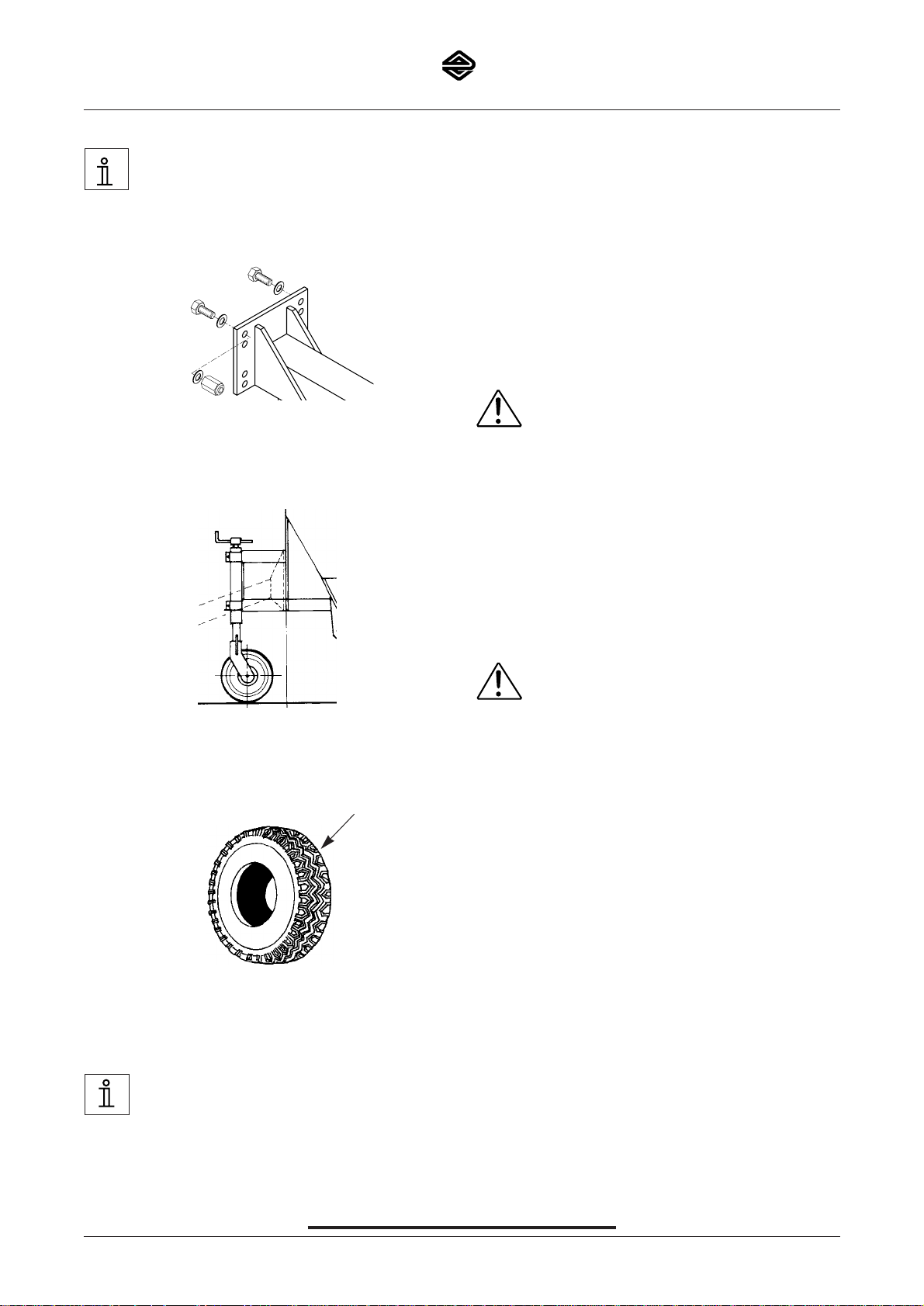
• The tow plate of the spreader must be vertical when the
vehicle is loaded.
• The draw bar is adjustable for height as well as length.
Important: When adjusting height, self-locking nuts (A)
must only be used once, i.e. always use new selflocking nuts. Nut (M14 DIN 985 A2) torque must be
120 Nm.
• The stabiliser/supporting leg facilitates
connection/disconnection of the spreader. Before driving, the driver must check that the stabiliser/supporting
leg has been lifted.
• The depth of the tyre tread pattern must be min. 1.6 mm.
For information on air pressure in the road tyres.
2.1.3.2 Work safety
• Protection devices: The equipment must not be
operated without protection devices.
• The drawbar position must not be above hori-
zontal position due to the risk of tipping.
See section 2.1.2 Total weight reference – support load.
• Driving gear: The warranty and liability become void if
changes are made to the driving gear.
• Oblique position: The road may have a maximum incli-
nation of 10%.
• The spreader must only be subjected to repair work
when the motor of the towing vehicle has been stopped.
• Following repair work, all safety devices must be connected to the spreader.
• Unauthorised persons are to be turned away from the
danger zone.
• Persons must not be in the immediate proximity of the
machine (1 m to the side of the machine) when the
machine is operating.
• Notice! - Only spare parts recommended by the manufacturer must be used.
2.1.3.3 Before driving
Before starting, the driver should check that:
• the tow plate of the spreader must be vertical
when the vehicle is loaded.
• the spreader’s towbar is correctly positioned and secured to the tow-bar on the vehicle.
• the stabilizers have been raised.
• the safety devices are functioning.
• electrical connections and power supply have been con-
nected.
• the lights are functioning.
• the operating device has been fitted.
• the air pressure in the tyres is correct.
Remember to check adjustments.
2.1.3.4 Safety during cleaning, repairs and main-
tenance
• When cleaning, repairs, maintenance and similar
work is performed on the spreader, the motor of
the towing vehicle must be stopped.
• Intervals of maintenance are divided into operating
hours and apply to normal operating terms.
• Please observe the specified intervals of maintenance.
• See the maintenance and inspection list.
• Only the spare parts approved and recommended by
the manufacturer must be used.
Please use the original Epoke-spare parts only.
• After repair, safety devices must be correctly fitted
again.
• It is not allowed to drive without safety devices.
6
epoke
®
SKE8-12-15-20
GB-0305.1
epoke
®

7
epoke
®
SKE8-12-15-20
GB-0305.1
epoke
®
2.1.3.5 Suggestions for a user guide
For a safe operation, the employer has to make
a user´s guide.
Employer is required to equip the tool with various devices
and make all necessary arrangements which correspond
to the applicable safety instruction, technical and medical
regulations.
The employer has to instruct the users of the dangers,
which may arise from operation with the tool and
precautions which must be made, and thereafter the
instruction must be repeated at regular intervals, at least
once a year.
The employer can fulfill this requirement by providing a
user´s guide. Please be aware of the legislation concerning the safety area.
You may pass on the following instructions/information of
the operation to your staff e.g.:
• Normal/permitted usage
• Abnormal usage
• Safety in public traffic
• The user must be aware of, that his/her presence in the
danger zone (working area) is forbidden.
• Information of safety devices.
• If a fault/defect arises in the equipment in the equipment
which may present a risk/danger to the insured parties,
the equipment must be stopped.
• First aid instructions
• Operational safety
• Reference to faults and their rectification
• Instructions regarding the warning instructions
• Permissible operating data
• Environmental protection
• Supervision during use
• Servicing
• Maintenance
• Repair work on load-bearing and other technical parts
relating to safety.
2.1.11 Lubricating grease
Long-term or repeated contact with the skin can entail irritation or serious skin problems. Wash thoroughly with
soap and water. Avoid inhalation of grease fumes. Avoid
wearing clothing wetted with grease.


8
epoke
®
SKE8-12-15-20
GB-0305.1
2.2 Product descriptions
2.2.0.1 Machine overview
1
.1 SKE spreaders
2.2 Stabiliser
2.3 Stabiliser spindle
2.4 Pull device
3.1 Impellor shaft
3.2 Delivery roller
3.3 Rubber base
3.4.1 Spring base
3.4.2 Spring base stop
3.6 Spring base adjustment
3.7.1 Transmission from drive wheel, over downward
gearing to delivery drum
3.7.2 Transmission from delivery drum to mixer
3.8 Handle for manual operation of connection and
disconnection of spreading
5.5 Holder for transmission exposure
5.6 Rubber bonnet for transmission exposure
2.2.1 Product description
The Epoke SKE towed spreader is a surface-dependent
drum spreader for spreading salt, sand and grit.
The SKE spreaders are fitted with the Epoke dosing
system where the delivery drum and mixer are pulled from
the spreader drive wheel via mechanical gearing.
The SKE may be equipped with different gearings
(SKE8/SKE12 - 11%, 24%, 36%, 76% and SKE15/SKE20
- 24%, 38%) in the delivery drum in relation to the wheels.
Operation: The wheels supply all the energy needed for
operation of the spreader, which is thus completely surfacedependent.
Dosing system: The material tank and the supporting
frame are welded together. The tank is fitted with a mixer
shaft and a dosing unit. The mixer shaft prevents the
spreading material from building up, thus grinding and
distributing the spreading material over the entire length of
the tank.
The dosing unit is situated under the mixer shaft, consists
of the spring-supported rubber base and the delivery
drum, whose function is to dose the material to the road
surface. The drop, i.e. the distance between the road and
the dosing drum, is relatively small, thus making the spreaders practically insensitive to side winds and turbulence.
As a result, the spreading material is delivered where it is
needed, i.e. on the road surface.
Material volume: The indicated material volume is delivered surface-dependently at any speed of driving, as the
dosing unit speed depends on the vehicle speed. Set the
material volume (at input) by adjusting the spring base.
Stabiliser: The SKE features an ungraduated adjustable
stabiliser.
5.5
3.3
3.2
3.1
3.3
3.4.1
2.2
2.3
3.6
3.8
3.4.2
1.1
2.4
5.6
3.7.1
3.7.2

9
epoke
®
SKE8-12-15-20
GB-0305.1
2.2.4
6
7
8
9
10
1
2
3
4
5
C
B
A
C
D

10
epoke
®
SKE8-12-15-20
GB-0305.1
2.2.4 Metering system
1 The Epoke principle
A - Impellor shaft with springs
B - Delivery roller with cams
C - Rubber base
D - Spring base
2 The impellor shaft pulverizes all lumps, distributes the
spreading material in the whole length of the hopper,
and ensures constant supply to the delivery roller.
Impellor springs: When replacing defect impellor
springs, the flat side is to point to the front in working
direction and be placed in two spirals, which start in
the centre, whereby the material is lead towards the
centre. Start with no. 1 in the middle. Turn the tube
1/4 turn forward in the working direction, mount pair
no. 2 equally on each side of no. 1. Turn 1/4 turn in
the working direction, mount pair no. 3 equally on
each side of the previously mounted pair etc.
3 Possibility for demounting defect impellor springs.
4 The delivery roller is provided with cams (A) which
bring the material through the spring adjusted rubber
base. The cams are available in different designs for
all types of material and dosages.
Great and many cams: Great amount (sand etc).
Small and less cams: Small amount (salt).
5 The delivery cams: If the cams are worn, they are to
be replaced. If the screws are rustbound, the cams
can be blasted with a hammer, and the screws be
loosened with tongs. To ease a replacement of cams
later, it is recommended to fill in approx. 1/4 l waste
oil into the delivery roller. This has not been done
from the works out of regard for the oil waste during
shipment.
6 The rubber bases are jammed under the clamping iron
and can be turned and worn on all edges provided that
they are turned in time, see also description of the
spring base.
7 The spring base presses the bottom rubber base
against the cams of the delivery roller, regulated by
the spring base adjustment. Defect springs by wearing are to be replaced. When the spring base is
open, all points of the springs are to be in line.
The spring base stop is adjustable and placed in
order to stop the movement of the spring base for
max. material quantity.
8 Spring base adjustment: The adjustment is obtained
by the pressure of the bottom rubber base with different strength against the delivery roller by means of
the spring base. The pressure is varied by the adjustment handle at the rear of the spreader.

11
epoke
®
SKE8-12-15-20
GB-0305.1
2.3.1 Technical data
Model SKE8 SKE12 SKE15 SKE20
Hopper capacity, m
3
0,725 0,9 1,25 1,65
Total width, mm 1285 1665 1665 2195
Track gauge, mm 790 1160 1000 1530
Spreading width - min., mm 1008 1390 1390 1918
Rim size 4.00 E x 9 4.00 E x 9 5.50F x 10 5.50F x 10
Tyre size, 10PR 6.00 - 9 6.00 - 9 7.50 - 10 7.50 - 10
Tyre size, 12PR 6.00 - 9 6.00 - 9 7.50 - 10 7.50 - 10
Tyre size, 14PR ----- ----- 7.50 - 10 7.50 - 10
Net weight, kg 400 500 600 720
Permitted total weight, kg 1200 1500 2660 3500
Permitted shaft load capacity, kg 1000 1200 2100 2800
Supporting load on draweye, kg 200 300 560 750
Speed, km/h 30 30 30 30

12
epoke
®
SKE8-12-15-20
GB-0305.1
2.3.2 Dimensioned sketch
SKE15, SKE20
SKE8, SKE12
2.4 Diagrams
2.4.3 Electrical diagram
Electrical diagram, see spare parts manual.
2.5 Corrosion protection
All Epoke-products were sandblasted with steel balls, zinc
dusted with 1-component epoxyester (does not apply to
non-corrosion-resistant components), first coated with 2component polyurethan and varnished with 2-component
polyurethan varnish.

13
epoke
®
SKE8-12-15-20
GB-0305.1
epoke
®
3 Demands to the place of mounting
3.1 Demands to the bed plate
Important! The spreader is to be loaded off onto
a solid, horizontal bed capable of bearing.
3.2 References to dangers which can be prevented by methods of mounting
Demands to the off-loading: The spreader is to be placed
with adequate space around itself in order to carry out
maintenance, lubrication, cleaning etc. comfortably and
safely. The distance from the spreader to a stationary
building must be at least 0.7 m, and between several
spreaders the distance must be at least 1.1 m.
4 Instructions for preparations
4.1.1 Connection with the towing vehicle
1. Make sure that the spreader cannot roll backwards.
Break blocks must be used on an even or very uneven
surface or on a slope.
2. Adjust the stabiliser or supporting leg so that the
towing vehicle hits the middle or just above the lowest
part of the coupling on the vehicle.
3. There must be no persons between the spreader and
the vehicle.
4. Coupling of spreader and vehicle. Replace the vehicle.
5. Once the coupling has been completed, check to
make sure that it is correct.
6. Connect the supply cables (electricity).
7. Turn op the stabiliser/supporting leg.
8. Remove brake blocks.
9 Check spreader light.
4.1.2 Disconnection
1. Secure the spreader by using
break blocks on an even or very uneven surface or on
a slope.
2. Lower the stabiliser/supporting leg.
3. Disconnect supply cables (electricity).
4. Disconnect the spreader.
5. There must be no persons between the spreader and
the vehicle.
6. Remove the vehicle from the spreader.
5 Operation instructions
5.0.1 Remote control
1. Spreading stop
2. Spreading - start
3. Material level indicator
4. Voltage control
5.1.5 Operating levers
As standard the spreader is supplied with manual remote
control of clutch for delivery roller and impellor.
The handle is placed onto the left transmission box of the
spreader.
Quantity control: The quantity control is done in differring
the pressure of the spring base against the delivery roller.
The pressure is varied through the handle at the rear of
the spreader.
1
2
3
4

14
epoke
®
SKE8-12-15-20
GB-0305.1
5.2 Instructions for Initial Operation
5.2.2 Adjustment of spreading quantity (metering)
At metering or check of quantity per m2you must be aware
that the width of the spread is 136% of the width of the
delivery roller when the road speed is 20 km/h or above.
The measuring tray corresponding to a width of spread of
1 metre must therefore be 1:1.36=0.735 m.
10 g/m2= 10 kg per driven km in measuring tray 0.735 m
20 g/m2= 20 kg per driven km in measuring tray 0.735 m
30 g/m2= 30 kg per driven km in measuring tray 0.735 m
40 g/m2= 40 kg per driven km in measuring tray 0.735 m
You may either hang the measuring tray up below the
delivery roller and drive exactly 1 km. Or you may activate
the wheel of the spreader and count the turns. In the latter
case the following calculation must be made:
Turns of wheel per km =
1000
D x π
D
Ex.: D = 0,540 m
= 589 turns per km
1000
0,540 x 3,14
5.4.2 Remote control
5.4.2.1 Correct installation
Direct current requirements for the electric control system
of the spreader: 11V - 32V.
When switching between 12V and 24V vehicles, working
lamp and rotating beacon must be switched accordingly.
5.4.2.2 Connection of remote control
• The electric remote control is connected to the spreader
by means of the multipoled plug on the remote control
cable, and connect it to the socket on the spreader.
• Plug the power supplying cable into the universal plug
on the vehicle (the lighter).
The remote control can be fastened in the cab using
mounting hardware (optional equipment), which is the
most suitable positioning for the remote control.
The remote control must be protected against the weather
when the spreader and thus the remote control are not in
use.
Gritting
Do not drive with engaged delivery roller without material in
the hopper in order to prevent unnecessary wear of the
rubber base.
If you wish to keep the marked width of spread the speed
should not exceed 25 - 30 km/h. At greater speeds the
width is increased through the wind, and widths of more
than 6,0 m may be acheived.

15
epoke
®
SKE8-12-15-20
GB-0305.1
5.12 Instructions for repair and assembly
Replacement of delivery roller and impellor
The shafts are drawn sidewards out of the rear plates of the
hopper. The holes are big enough to let through the delivery
roller and the impellor mounted with cams and springs.
Remember to loosen both allan screws in the flange bearings when the delivery roller and the impellor are dismounted. When mounting the delivery roller and the impellor the
tallow string tightenings are to be connected carefully and
the shaft ends to be wiped and greased. The chain wheels
must also flush.
6 Maintenance
6.2.1 Cleaning
All Epoke spreaders have been sandblasted, zinc dust
primed and primed before being painted with laquer, and
they are therefore extremely well-protected against rust.
However it is recommended - espescially after spreading
salt and if there are longer pauses between operations that the spreader is washed down with water after use.
Regular control extends the lifetime of the spreader and
guarantees a safer function.
6.2.2 Maintenance
Cleaning remote control.
Clean the remote control with a slightly moistened cloth
and wipe with a dry cloth.
Maintaining remote control.
Connectors and strain reliefs should be checked at regular intervals or at least every 100 operating hours. Defect
connectors must be replaced.
All moving transmission parts and bearings should be
lubricated with grease, see inspection list - mechanical
item 6.3.1.
The driving shafts are suspended in spherical roller bearings with tightenings and in flange bearings. They should
be greased only once a year. Over-greasing may spoil the
tightenings. Likewise too much grease may cause the
bearings to overheat.
Delivery roller and impellore are suspended in flange
bearings by a laminated tightening. The bearings are greased at the factory and do not need much greasing, but
for the sake of the tallow tightenings mounted behind a
frquent greasing is recommended, at least after each 25
hours ‘ operating.
Spring base adjustment is lubricated through the lubrication nipple with grease, see inspection list - mechanical
item 6.3.1
Defect cams are to be replaced. If the screws are rustbound, the cams can be blasted with a hammer, and the
screws can be loosened with tongs. In order to avoid this,
it is recommended, before use to loosen a cam and fill in
approx. 1/4 litre waste oil in the delivery roller.
Impellors: Defect springs are to be replaced, see metering system item 2.2.4.
Spring base: Defect springs are to be replaced. When
the spring base is wide open, the points of the springs
must be in line.
Rubber base: The rubber bases are wedged in under
clamping iron and can be turned and worn on all 4 edges,
provided that they are turned in time.
Roller chains: Control that they are tightened. They shall
be tightened in such a way that they by means tightening
them totally.
Clutch: Free function is checked. Otherwise clean and grease all parts. When the spreader is engaged is engaged the
pawl chamber, the pawl retainer and the pawl must turn free
without touching the stripper. When the spreader is disengaged the pawl must be combletely in bottom.
6.2.3 Storing
After the winter season it is recommended that the spreader is cleaned, protected against corrosion, lubricated and
has damages in the laquer repaired.
The spreader must be stored with an open (completely
open) spring base.
Storing remote control
When not in use, the remote control should be stored in a
dry place.
5.11 Procedure in case of failure
Problems Cause Remedy
1. Electric remote control out of order 1a. No power 1a. Connect power
1b. Fuse blown 1b. Replace the fuse
2. The spreader does not start 2a. No power on the system 2a. See item 1.
when using the remote control 2b. Bad connection in the 4-poled plug 2b. Clean/replace the plug
2c. Engine defective 2c. Replace engine
3. The spreader does not start manually 3a. Scraper does not move/ 3a. Check connections to start/stop
eccentric does not turn handle/axle (tailstock screw has
come loose – tighten)
3b. Chain broken 3b. Mount a new chain
4. Defective light/indicator 4a. No power 4a. Check connections
4b. Bad connection in the 7-poled plug 4b. Clean/replace the plug
4c. Bulb broken 4c. Replace bulb

16
epoke
®
SKE8-12-15-20
GB-0305.1
Date:
Signed:
1 Flanged bearings:
At the delivery roller and
the impellor shaft Ball bearing grease 25 h
2Tallow string packing:
At the delivery roller and
the impellor shaft 25 h ***
3 Delivery roller:
Cams 50 h Visual inspection. Worn
cams to be replaced.
4 Impellor springs 50 h Worn springs to be replaced
5 Rubber bases 50 h The rubber bases are wed-
ged in under the clamping
iron and can be turned and
worn on all edges - provided
that they are turned in time.
6 Spring base 50 h Visual inspection. When
the spring base is wide
open, the points of the
springs must be in line.
Worn springs to be replaced
7 Chain transmission:
Roller chains 50 h Check that the chains are
tight. The chains must not,
however, be firmly tightened.
Rolling chain - lubrication Wynn's Viscotene 50 h Silicone spray grease
8 Wheel nuts *140 Nm(14,0 kpm) 50 h *Tightening moment
9 Air pressure see tyre list 50 h
10 Spring base adjustment Grease 100 h
*** The tallow string packing consists of a rubber collar in which the tallow string of 2 1/2 windings is pressed in between
flange bearing and covering plate. When the flange bearing is mounted, the space between tallow string and flange
bearing is filled withe grease, which supports the tightening effect of the tallow string. Lubrication is carried out with
intervals of 25 hours of operation. If the grease penetrates into the hopper through the tallow string packing when lubricating, the tallow string should be replaced.
To be checked
Pos.
Machine:
Inspection list - mechanical
Measure size
and test size.
Operational
means and consumption means
Interval Result of
inspection
Comment
6.3.1.

17
epoke
®
SKE8-12-15-20
GB-0305.1
Date:
Signed:
11 Coupling 100 h Check that the ratchet is
working freely, alternatively
clean and grease all parts.
When the spreader is connected, the ratchet chamber, ratchet holder and ratchet must move freely
without touching the scraper. When the speeder is
disengaged, the ratchet
must be fully compressed.
12 Pawl for clutch Lubricating oil 100 h
13 Strickler Lubricating oil 100 h
14 Clutch lever Lubricating oil 100 h
15 Eccentric Lubricating oil 100 h
16 Stabiliser and support leg Lubricating oil 100 h
17 Nuts for drawbar *120 Nm (12,0 kpm) Before *Torque moment
each season
18 Greasing bearing Ball bearing grease Before
(drive wheel axle) each season
19 Salt spreading During longer It is recommended that the
pauses in spreader be flushed with
spreading water.
To be checked
Pos.
Machine:
Inspection list - mechanical
Measure size
and test size.
Operational
means and consumption means
Interval Result of
inspection
Comment
6.3.1.

18
epoke
®
SKE8-12-15-20
GB-0309.2
6.3.4 Grease
Grease:
Spreaders have been lubricated using Texaco products,
either mineral lubricating grease or biological lubricating
grease.
Mineral lubricating
grease: Texaco Texando CX EP 2.
Biological lubricating
grease: Texaco Biostar Grease LC EP 2.
6.7 Reference to suitable spare parts
Rubber base 8x210 (A), 12x210 (B) - See spare parts
manual.
Cams - See spare parts manual.
Impellor springs - See spare parts manual.
Tyres - See spare parts manual.
A
B

19
epoke
®
SKE8-12-15-20
GB-0305.1
Tested
Inspection
Steadying wheel
Control at use (Visual inspection)
Date Signed Result Date Signed
7.1.2

20
epoke
®
SKE8-12-15-20
GB-0305.1
Tested
Inspection
Dry matter container
Control at use (Visual inspection)
Date Signed Result Date Signed
• Visual checks should include checks for exterior damage, deformities, wear and tear and corrosion.
• Implementing safety devices.
7.1.6

21
epoke
®
SKE8-12-15-20
GB-0305.1
Tested
Inspection
Draw bar
Control at use (Visual inspection)
Date
Signed
Result Date Signed
• TThe drawbar is adjustable in height.
Important: When adjusting height, self-locking nuts must only be used once, i.e. always use new self-locking nuts. Nut
(M14 DIN 985 A2) torque is 120 Nm.
• Do not perform subsequent changes on the drawbar, e.g. welding repairs.
• Check the driving gear for wear at regular intervals.
• Replace the bush at the “eye”. The bush may be replaced by rolling or pressing it in. Do not insert a bush by welding
or tacking.
7.1.12

22
epoke
®
SKE8-12-15-20
GB-0305.1
7.1.20 Tyre list
I
Mashine Ident. Torque moment
type no: kpm Size of tyre Ply Profile Epoke no:
TKG12 1101
TKB9-280 1107 3.00-4" 6 T-991 impl. 82251314 7 101,5
TK12E 1210 14 6.00-9" 10 T-523 82251114 8,5 123,25
TK12E-275 1211 14 6.00-9" 12 T-523 HS 82251505 10 145
TKEB12 1301 14 6.00-9" 12 T-523 Steel-Belt 82253612 8,1 117,45
TKEB9-275 1306
TMK10 1400 14 6.00-9" 10 T-523 82251114 8,5 123,25
TMK10-275 1405 14 6.00-9" 12 T-523 HS 82251505 10 145
TMK7 1404 14 6.00-9" 12 T-523 Steel-Belt 82253612 8,1 117,45
TMK7GT 1406
TT10H2 1610 3.00-4" 6 T-991 impl. 82251314 7 101,5
TT10H6 1611 14 6.00-9" 10 T-523 82251114 8,5 123,25
TT10H2-275 1612 14 6.00-9" 12 T-523 HS 82251505 10 145
TT10H6-275 1613 14 6.00-9" 12 T-523 Steel-Belt 82253612 8,1 117,45
SW2000 2425 3.00-4" 6 T-991 impl. 82251314 7 101,5
14 6.00-9" 6 T-523 82251002 2,2 31,9
CS1000 1507 14 6.00-9" 10 T-523 82251114 8,5 123,25
CS1000 MKII 1510 14 6.00-9" 12 T-523 HS 82251505 10 145
CS1000 MKII
1511 14 6.00-9" 12 T-523 Steel-Belt 82253612 8,1 117,45
Air pressure at
50 km/h
bar psi
SKE8 1001 14 6.00-9" 10 T-523 82251114 8,5 123,25
SKE12 1003 14 6.00-9" 12 T-523HS 82251505 10 145
14 6.00-9" 12 T-523Steel belt 82253612 8,1 117,45
SKE15 1004 4.00-4" 6 T-991 82251435 7 101,5
SKE20 1005 14 7,50-10" 10 T-523 82251071 6,5 94,25
14 7,50-10" 14 T-523HS 82251501 9 130,5
14 6.00-9" 6 T-523 82251002 4,3 62,35
14 6.00-9" 12 T-523HS 82251505 10 145
ITM35 1501 4.00-8" 6 T-49 HS 82251278 5,2 75,4
ITM45 1502 155/70R-13" 75 Q M+S 82250006 2,2 31,9
ITM60 1503
Epomini 5 2.00-16" VM 100 82256258 2,5 36,25
Epomini 20 2.75-17" VM 100 82256299 2,75 39,875
IGLO S2400 2490 18x8.0-10 82250008 6 87
2491 185-R14" 8 P75 82250001 4,5 65,25
2492 185-R14" 8 P75 82250001 4,5 65,25
2493 18x8.0-10 82250008 6 87
2494 185-R14" 8 P75 82250001 4,5 65,25
2495 185-R14" 8 P75 82250001 4,5 65,25
TS1000 1551 9 185QR-14" P75 82252279 3 43,5
9 185-R14" 8 P75 82250001 3 43,5
TS1000 1552 9 215/75R-17,5" L71 82250005 8,5 123,25
PW803H 3105 10,5 155/70R-13" 75 Q M+S 82250006 1,5 21,75
PW23H 3130
SWxxxx 14 185R-14" MS PLUS 3 Q 82252279 1,5 21,75
EpoJet
PWV87

23
epoke
®
SKE8-12-15-20
GB-0305.1
8.1

24
epoke
®
SKE8-12-15-20
GB-0305.1
8.4 Certificate of Quality Management System (ISO 9001)
This quality management system is a very important requirement in order to assert oneself in international trade and frequently also in order to participate in open tenders.
The company has held the certificate since April 21, 1993, and it is applicable to the Epoke product range, including grass
mowers, spreaders, sweepers, snow ploughs, which have all been subject to ISO 9001 testing.

25
epoke
®
SKE8-12-15-20
GB-0305.1
9 Overview of standards
EUROPEAN STANDARD
EN 292-1 : 1991
Safety of machinery - Basic concepts - General principles for design - Part 1: Basic terminology, methodology.
EN 292-2 : 1991/A1 : 1995
Safety of machinery - Basic concepts, general principles for design - Part 2: Technical principles and specifications.
EN 294 : 1992
Safety of machinery - Safety distances to prevent danger zones being reached by the upper limbs.
EN 349 : 1993
Safety of machinery - Minimum gaps to avoid crushing of parts of the human body.
EN 418 : 1993
Safety of machinery - Emergency stop equipment, functional aspects - Principles for design.
EN 811 : 1996
Safety of machinery - Safety distances to prevent danger zones being reached by the lower limbs.
EN 953 : 1997
Safety of machinery - Guards - General requirements for the design and construction of fixed and movable guards.
EN 1037 : 1996
Safety of machinery - Prevention of unexpected start-up.
EN 1050 : 1997
Safety of machinery - Principles for risk assessment.
EN 1088 : 1996
Safety of machinery - Interlocking devices associated with guards - Principles for design and selection.
EN 60204-1 : 1998
Safety of machinery - Electrical equipment of machines - Part 1: General requirements.

26
epoke
®
SKE8-12-15-20
GB-0305.1
20 Index
A
Abnormal use, 4
Adjustment of spreading quantity (metering), 14
Before driving, 6
C
CE-mark, 3
Certificate of Quality Management System, 24
Certificates, 23
Cleaning, 15
Connection of remote control, 14
Connection with the towing vehicle, 13
Control and test sketch, 19
Copyright, 2
Correct installation, 14
Corrosion protection, 12
Country of origin, 3
D
Demands to the bed plate, 13
Demands to the place of mounting, 13
Descriptions, 4
Diagrams, 12
Dimensioned sketch, 12
Directives applied, 3
Disconnection, 13
Dosage system, 9
Draw bar, 21
Dry matter container, 20
E
Electrical diagram, 12
Electrical hazard, 4
EU certificate of conformity, 3, 23
G
General safety measures, 5
General, 4
Grease, 18
H
Handling, 4
Hazard caused by materials and substances, 5
Hazard caused by noise, 5
Hazard caused by radiation, 5
Hazard caused by vibrations, 5
Hazards presented by the machine, 4
I
Identification, 2
Information on restrictions on use, 4
Inspection list – mechanical, 16
Inspection lists and overviews, 16
Instructions for Initial Operation, 14
Instructions for repair and assembly, 15
L
Lubricating grease, 7
M
Machine overview, 8
Maintenance, 15
Manufacturer and supplier, 2
Mechanical hazard, 4
Model and type specification, 3
N
Normal use, 4
O
Operating levers, 13
Operation instructions, 13
Overview of standards, 25
P
Personal protective measures, 4
Procedure in case of failure, 15
Product description, 8
Q
Quality system certificate, 3
R
Reference to permitted total weight, 5
Reference to safety measures for specific operating conditions, 6
Reference to suitable spare parts, 18
References to dangers which can be prevented by methods of mounting, 13
Remote control, 13, 14
Rules for total weight of towed vehicles, 4
S
Safety measures, 5
Safety measuresWork safety, 6
Sikkerhed ved rengøring, reparation og vedligeholdelse, 6
Standards applied, 3
Start no. and date, 3
Steadying wheel, 19
Storing, 15
Suggestions for a user guide, 7
T
Technical data, 11
Technical documentation, 2
Thermal hazard, 5
Transport and handling, 4
Tyre list, 22
W
Warranty and liability, 2
Work
 Loading...