

Page 1
INSTALLATION MANUAL
ES-SUB-WIRELESS-KIT
Page 2
page | 2
www.snapav.com Support 866.838.5052
INTRODUCTION
Thank you for purchasing Episode® Electronics. To complete installation, follow
these guidelines. Visit our website for design recommendations and speaker
calculators.
Subwoofer placement can have a large impact on the overall sound quality of low
frequencies. This Episode® wireless subwoofer kit allows subwoofer placement
anywhere in the room without running wires.
CONTENTS
• 1x Wireless transmitter
• 1x Wireless receiver
• 2x Power supply
SETUP
SYSTEM CONNECTIVITY
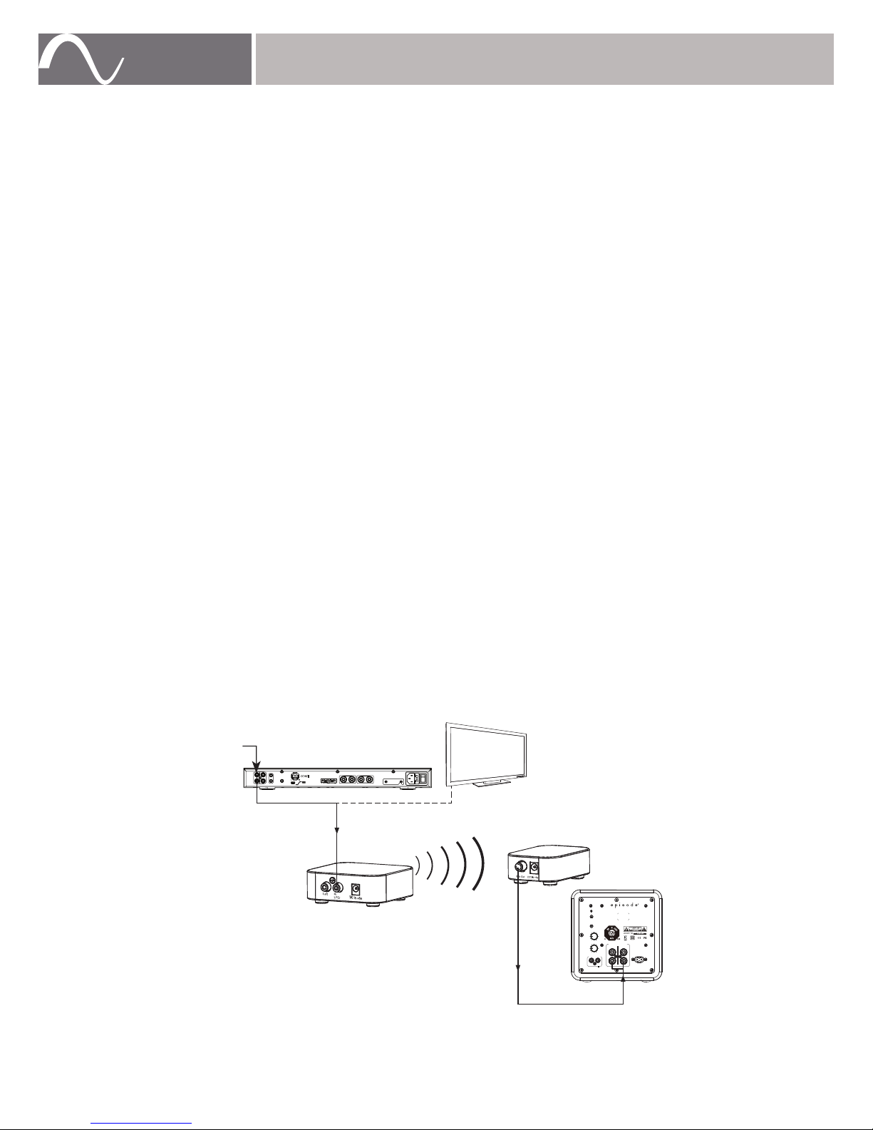
1.
Use high-quality shielded RCA cables with low impedance, and high-quality
connectors. Connect the wireless transmitter to the AV receiver utilizing a
dedicated subwoofer connection (LFE) or L/R preamp output or to a TV using
an RCA cable.
2.
Use a dedicated subwoofer connection (LFE) or left/right preamp output.Connect
the wireless to the LEFT or LFE input on the subwoofer. A splitter may also
be used to send the signal to both the LEFT/RIGHT input for higher volume
levels on some subwoofers.
Refer to the subwoofer owner’s manual for specific information on connections
and setup.
100-240V 50/60Hz
HIGH LEVEL INPUT
LFE
ES-SUB-EVO6-100
VOLUME
PHASE
AUTO
STATUS
OFF ON
R L
R L
1.6A
Designed and Engineered in USA
Manufactured in China
CROSSOVER
LOW LEVEL
0˚ 180˚
50
100
LFE
MIN MAX
IN
R
L
(LFE)
OUT
OUT
IN IR UPDATE
OPERATE
TRIGGER
DC 12V
EA-AMP-SUB-1D-500R
SUB 1
SUB 2
Total Impedance
(Sub 1 + Sub 2) Minimum 4Ω
100-120V AC
220-240V AC
FUSE T8AL/250V
100-120V~60Hz/220-240V~50Hz 500WATTS
Designed and Engineered in USA
Made in China
A/V Receiver
Transmitter
RCA Output on TV
Receiver
Subwoofer
Subwoofer Cable
RCA
Cable
Preamp or
Subwoofer (LFE)
Output
www.snapav.com Support 866.838.5052
Page 3
page | 3
© 2015 Episode®
SUBWOOFER PLACEMENT
Subwoofer placement has an effect on overall audio performance.
The strongest audio output will likely occur if the subwoofer is placed in a corner
of the room on the same wall as the front channel speakers. This is known as
the boundary effect and will emphasize certain bass frequencies while canceling
others. Some listeners will find this to be the best sounding result, while others
may find it overly “boomy” or muddy.
Once the wireless kit is paired, experiment with subwoofer placement to find the
location that delivers the best audio performance.
PAIRING YOUR EPISODE® WIRELESS KIT
Initial pairing may be performed without the audio signals connected. This may be
preferred for easier access to the pairing buttons and power connections.
Follow the instructions below to pair wireless transmitter and receiver.
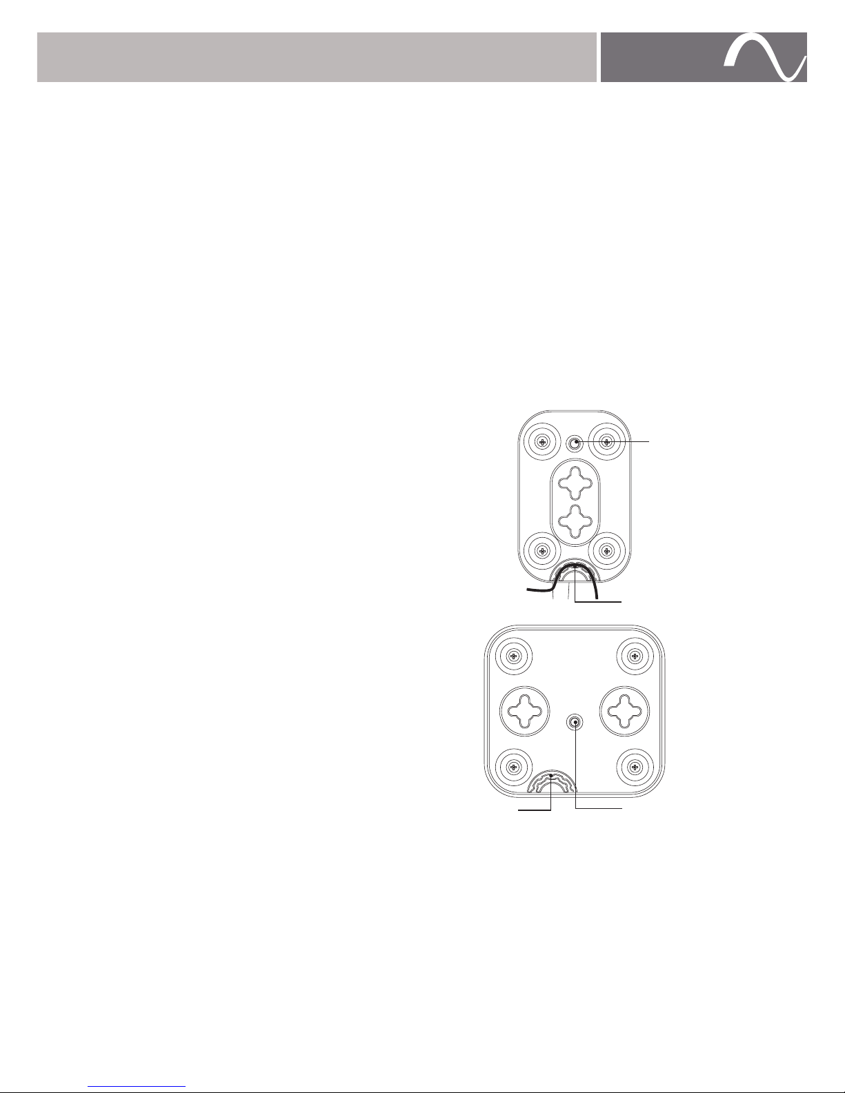
1.
Plug in all transmitters and receivers.
The power cords can be routed
through the strain relief detail to
prevent the cord from being pulled
out.
2.
Press and hold the pair button on the
receiver until the LED flashes. Repeat
this procedure for all receivers if
using more than one.
NOTE:
Up to 4 receivers may be paired to
1 transmitter
3. Press and hold the pair button on the
Transmitter.
4.
All LEDs should stop flashing and stay solid within 5 seconds.
5.
Unplug all units and mount in final locations. Pairing is persistent and will not
be lost when unplugged.
NOTE:
Wireless devices may be susceptible to RF interference from other
devices. To reduce potential interference and maximize wireless performance,
check the proximity to other wireless devices and relocate them accordingly if
interference is present. Signal interference created by microwave ovens, ceiling
fans,or other appliances will subside when those devices are not in use.
Pair
Button
Receiver
Strain Relief
Detail
Transmitter
Pair Button
Strain Relief
Detail
© 2015 Episode®
Page 4
SPECIFICATIONS
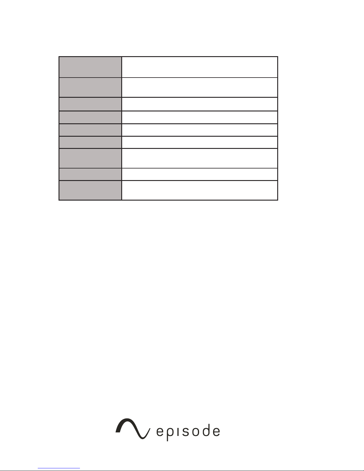
Modulation
Operating
Frequency
2412 - 2464 MHz
Channel Width
<22 MHz
Latency
<20 ms
Typical Range
30 ft. max. (10m)
Transmitter
Power
0 dB
S/N
84 dB
Max Input Signal
(LFE)
1.84 V
WARRANTY
Lifetime Limited Warranty
Episode® Accessories have a Lifetime Limited Warranty. This warranty includes
parts and labor repairs on all components found to be defective in material or
workmanship under normal conditions of use. This warranty shall not apply to
products that have been abused, modified or disassembled. Products to be
repaired under this warranty must be returned to a designated service center
with an assigned return authorization (RA) number. Contact technical support at
[email protected] for an RA number.
CONTACTING TECHNICAL SUPPORT
866.838.5052
© 2015 Episode®
Rev: 151116-1445
QPSK
Page 5

FCC Information and Copyright
This equipment has been tested and found to comply with the limits for a Class B digital device,
pursuant to part 15 of the FCC Rules.
These limits are designed to provide reasonable protection against harmful interference in a residential
installation. This equipment generates,
uses and can radiate radio frequency energy and, if not installed and used in accordance with the
instructions, may cause harmful interference
to radio communications. However, there is no guarantee that interference will not occur in a particular
installation. If this equipment does
cause harmful interference to radio or televisi on reception, which can be determined by turning the
equipment off and on, the user is
encouraged to try to correct the interference by one or more of the following measures:
—Reorient or relocate the receiving antenna.
—Increase the separation between the equipment and receiver.
—Connect the equipment into an outlet on a circuit different from that to which the receiver is
connected.
—Consult the dealer or an experienced radio/TV technician for help.
This device complies with part 15 of the FCC Rules. Operation is subject to the
following two conditions:
(1)This device may not cause harmful interference, and
(2) this device must accept any interference received, including interference that may
cause undesired operation.
changes or modifications not expressly approved by the party responsible for compliance could
void the user's authority to operate the equipment.
This equipment complies with FCC radiation exposure limits set forth for an uncontrolled
environment .This equipment should be installed and operated with minimum distance 20cm
between the radiator& your body. This transmitter must not be co-located or operating in
conjunction with any other antenna or transmitter.
28
 Loading...