

Page 1
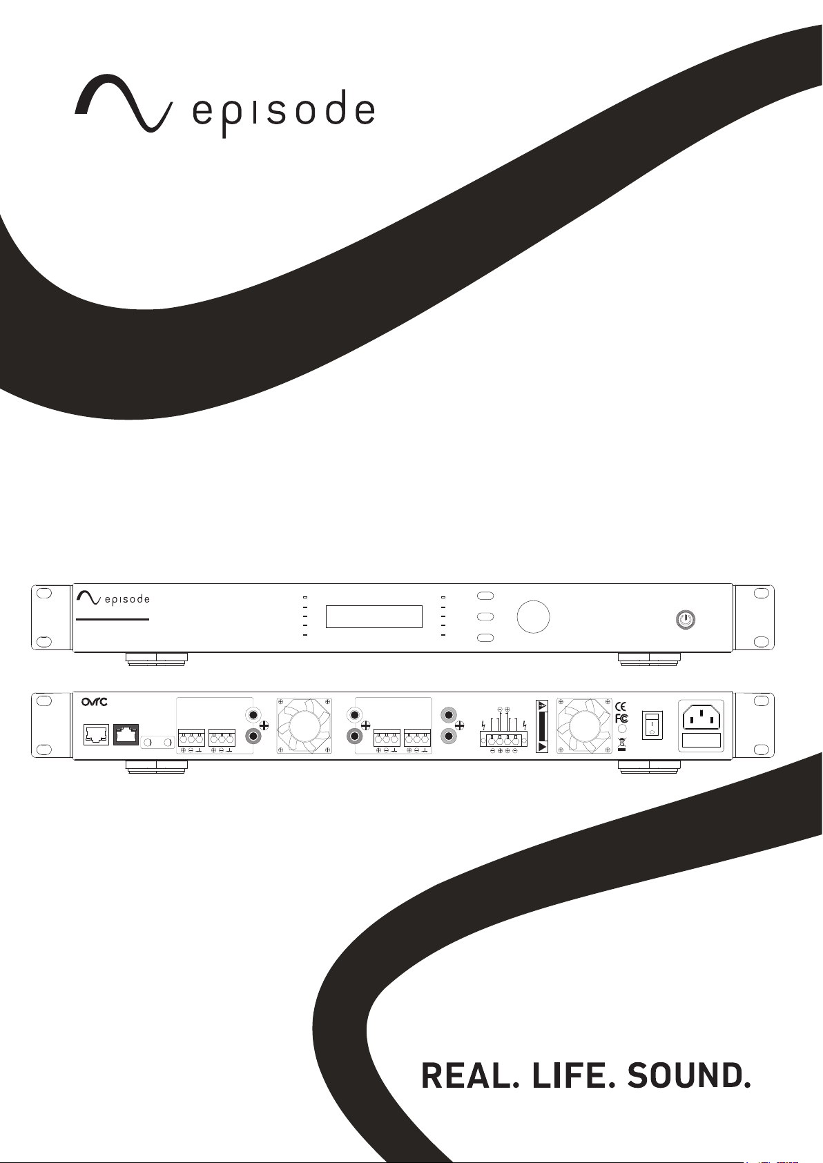
PRODUCT MANUAL
EA-AMP-HYB-2D-1000
EA-AMP-HYB-2D-2000
NETWORK
CONTROL
LINK ACT
SERIAL
CONTROL
TRIGGER
DC 12 V
IN
PROTECT
CLIP
-10
-20
SIGNAL
CH1
LINE IN
CH2
CH1
CH1
CH1
LINE OUT
CH2
OUT
CH2
CH2
PROTECT
CLIP
CH.SEL
-10
-20
MENU
SIGNAL
CH2
DIGITAL
CH1
IN
OUT
BACK
SPEAKER OUT
BRIDGE
CH2 CH1
ADJUST | SET
A
T
TENTION ! RISQUE DE CHOC ! ÉLECTRIQUE P
AS OUVRIR !
RISK OF ELECTRICAL SHOCK!
DO NOT OPEN!
CAUTION
!
U
C UL
LIFTED
L
EA-AMP-HYB-2D-1000
118V110-120V AC-60H-230W
230V230-240AC-50Hz-230W
ON
OFF
230V FUSE T4A H250V
110 V FUSE T8AH 250V
Use only a 250V fuse
Employer uniquement aux
un fusible de 250V
Page 2

page | 2
www.snapav.com Support 866.838.5052www.snapav.com Support 866.838.5052
Page 3

CONTENTS
Important Safety Instructions ..................................................................................................................................... 4
Introduction ......................................................................................................................................................................6
IP/OvrC CONTROL ............................................................................................................................................................ 6
Contents ....................................................................................................................................................................... 6
TOOLS ................................................................................................................................................................................. 6
SPEAKER RECOMMENDATION ..................................................................................................................................... 6
Front Panel .................................................................................................................................................................. 6
Rear Panel ................................................................................................................................................................... 7
SOURCE CONNECTIONS .................................................................................................................................................8
SPEAKER CONNECTIONS AND OUTPUT MODE ....................................................................................................... 9
AMPLIFIER POWER CONTROL .................................................................................................................................. 10
Front Panel Power Button ................................................................................................................................... 10
Resetting the Amplifier ......................................................................................................................................... 10
12 Volt Trigger ......................................................................................................................................................... 10
Audio Sense ............................................................................................................................................................. 10
Power State.............................................................................................................................................................. 10
VOLUME CALIBRATION ............................................................................................................................................... 10
Calibration Setup Tips ........................................................................................................................................... 10
COMMON DEVICE SETUPS AND STEPS FOR CALIBRATING VOLUME: ........................................................... 11
Triad Audio Matrix to Analog Input: .................................................................................................................. 11
SPEAKER PRESETS ...................................................................................................................................................... 11
Using Presets with the Local Display ............................................................................................................... 12
Using Presets in the Web Interface .................................................................................................................. 12
Loading Preset Files .............................................................................................................................................. 13
Additional Preset Files .......................................................................................................................................... 13
TROUBLESHOOTING .................................................................................................................................................... 16
Specifications .......................................................................................................................................................... 16
CONTACTING TECHNICAL SUPPORT........................................................................................................................ 17
page | 3
© 2021 Wirepath Home Systems, LLC
Page 4
page | 4
CAUTION
Risk of Electrical Shock!
DO NOT OPEN!
!
ATTENTION ! RISQUE DE CHOC ! ÉLECTRIQUE PAS OUVRIR !
The lightning flash with arrowhead symbol, within an equilateral triangle, is intended to alert
the user to the presence of uninsulated dangerous voltage within the product’s enclosure that
may be of sufficient magnitude to constitute a risk of electric shock to persons.
The exclamation point within an equilateral triangle is intended to alert the user to the presence
of important operating and maintenance (servicing) instructions in the literature accompanying
the appliance.
IMPORTANT SAFETY INSTRUCTIONS
WARNING: To reduce the risk of fire or electric shock, do not expose this apparatus to rain or moisture.
1. Read these instructions.
2. Keep these instructions.
3. Heed all warnings.
4. Follow all instructions.
5. Do not use this apparatus near water.
6. Clean only with dry cloth.
7. Do not block any ventilation openings. Install in accordance with the manufacturer’s instructions.
8. Do not install near any heat sources such as radiators, heat registers, stoves, or other apparatus
(including amplifiers) that produce heat.
9. Do not defeat the safety purpose of the polarized or grounding-type plug. A polarized plug has two
blades with one wider than the other. A grounding-type plug has two blades and a third grounding
prong. The wide blade or the third prong are provided for your safety. If the provided plug does not
fit into your outlet, consult an electrician for replacement of the obsolete outlet.
10. Protect the power cord from being walked on or pinched, particularly at plugs, convenience
receptacles, and the point where they exit from the apparatus.
11. Only use attachments/accessories specified by the manufacturer.
12. Use only with the cart, stand, tripod, bracket, or table specified by the manufacturer, or sold
with the apparatus. When a cart is used, use caution when moving the cart/apparatus
combination to avoid injury from tip-over.
13. Unplug this apparatus during lightning storms or when unused for long periods of time. Refer
all servicing to qualified service personnel. Servicing is required when the apparatus has been
damaged in any way, such as power-supply cord or plug is damaged, liquid has been spilled or
objects have fallen into the apparatus, the apparatus has been exposed to rain or moisture, does
not operate normally, or has been dropped.
14. This product employs a Class I (or grounded) construction and shall be connected to a mains
socket outlet with a protective earthed (or ground) connection.
15. DO NOT EXPOSE THIS EQUIPMENT TO DRIPPING OR SPLASHING AND ENSURE THAT NO OBJECTS
FILLED WITH LIQUIDS, SUCH AS VASES, ARE PLACED ON THE EQUIPMENT.
16. TO COMPLETELY DISCONNECT THIS EQUIPMENT FROM THE AC MAINS, DISCONNECT THE POWER
SUPPLY CORD PLUG FROM THE AC RECEPTACLE.
17. THE MAIN PLUG OF THE POWER SUPPLY CORD SHALL REMAIN READILY OPERABLE.
18. CAUTION: TO REDUCE THE RISK OF ELECTRICAL SHOCK, DO NOT REMOVE COVER. NO USER
SERVICEABLE PARTS INSIDE. REFER SERVICING TO QUALIFIED SERVICE PERSONNEL.
www.snapav.com Support 866.838.5052
www.snapav.com Support 866.838.5052
Page 5
page | 5
CAUTION
Risk of Electrical Shock!
DO NOT OPEN!
!
ATTENTION ! RISQUE DE CHOC ! ÉLECTRIQUE PAS OUVRIR !
Le flash de foudre avec le symbole de pointe de flèche, dans une triangle équilaterale, est prévu
pour alerter l’utilisateur à la présence de la tens ion dangereuse non isolée dans la clôture du
produit qui peut être de la grandeur suffisante pour constituer un risque de décharge électrique
aux personnes..
Le point d’exclamation dans une triangle équilaterale est prévu pour alerter l’utilisateur à la
présence des instructions importantes de fonctionnement et d’entretien (entretien) dans la
littérature accompagnant l’appareil.
CONSIGNES DE SÉCURITÉ IMPORTANTES
Avertissement: Pour réduire le risque d’ incendie ou un choc électrique, ne pas exposer cet appareil à la
pluie ou à l’humidité.
1. Lisez ces instructions.
2. Conservez ces instructions.
3. Respectez tous les avertissements.
4. Suivez toutes les instructions.
5. Ne pas utiliser cet appareil près de l’eau.
6. Nettoyer avec un chiffon sec.
7. Ne pas bloquer les ouvertures de ventilation . Installer conformément aux instructions du fabricant.
8. Ne pas installer près de sources de chaleur telles que des radiateurs , registres de chaleur, poêles
ou autres appareils (incluant les amplificateurs) qui produisent de la chaleur.
9. Ne pas contourner le dispositif de sécurité de la fiche polarisée ou de mise à la terre . Une fiche
polarisée possède deux lames dont une plus large que l’autre . Une fiche de terre a deux lames et
une troisième broche de mise à la terre . La lame large ou la troisième broche sont fournies pour
votre sécurité . Si la fiche fournie ne rentre pas dans votre prise, consultez un électricien pour le
remplacement de la prise obsolète.
10. Protégez le cordon d’alimentation ne soit piétiné ou pincé, en particulier au niveau des fiches , des
prises de courant et le point de sortie de l’appareil.
11. N’utilisez que des fixations / accessoires spécifiés par le fabricant.
12. Utilisez uniquement avec le chariot, le trépied, le support ou la table spécifiépar le fabricant, ou
vendu avec l’appareil. Quand un chariot est utilisé, faites attention en déplaçant l’ensemble
chariot/appareil pour éviter les blessures en cas de renversement.
13. Débranchez cet appareil pendant les orages ou lorsqu’il n’est pas utilisépendant de longues périodes
de time. Refer à un technicien qualifié personnel . Une réparation est nécessaire lorsque l’appareil a
étéendommagé de quelque façon que ce cordon d’ alimentation ou la prise estendommagé , du liquide
a été renversé ou des objets sont tombés dans l’appareil, l’appareil a été exposé à la pluie ou à l’humidité
,ne fonctionne pas normalement , ou s’il est tombé .
14. Ce produit utilise une classe I ( ou la terre) construction et doit être raccordé à une prise de courant
mise à la terre avec une protection ( ou masse) .
15. NE PAS EXPOSER CET APPAREIL À éclaboussures et s’assurer qu’aucun OBJET REMPLI DE LIQUIDE
, TEL QU’UN VASE , sont placés sur le MATÉRIEL .
16. Pour déconnecter totalement cet appareil du secteur, débranchez la CORDON D’ALIMENTATION fiche
de la prise secteur.
17. LA PRISE PRINCIPALE DU CORDON D’ALIMENTATION doit rester facilement accessible .
18. ATTENTION: POUR RÉDUIRE LE RISQUE DE CHOC ÉLECTRIQUE, NE PAS RETIRER. NO réparable par
l’utilisateur pièces à l’intérieur. CONFIER L’ENTRETIEN DE PERSONNEL QUALIFIÉ .
© 2021 Wirepath Home Systems, LLC
Page 6
page | 6
INTRODUCTION
Thank you for purchasing an Episode® amplifier. To get started, follow these instructions. For detailed
specifications and configuration recommendations, see the product manual posted on our website.
This two-channel amplifier (70V or 8 ohm selectable on each) is designed for applications requiring
two-channel stereo audio or two mono zones of audio with different sources or levels. Channels can also
be bridged to increase output power and send a singular mono signal.
IP/OVRC CONTROL
Connect the amplifier to a LAN with internet access to activate an OvrC connection. Create a new
account at www.OvrC.com, or log in to an existing account. Select Add a Device and enter the device’s
MAC address and serial number (this information can be found next to the service tag on the product).
If OvrC locates the device, directions to continue setup will be displayed.
The local UI can be accessed without OvrC by entering the IP address into a web browser. IP address
can be displayed on the front panel via toggling to the “device details” menu. Default login information
is shown below:
• Username: episode
• Password: episode
Popular Control System and RS-232 drivers can be found via the Product Support tab.
NOTE: To display the IP address of the amplifier, press the MENU button until “Device Info” is displayed,
then turn the Adjust/Select knob.
CONTENTS
• 1 x EA-AMP-HYB-2D-1000/2000 amplifier
• 1 x detachable 1.8 m (6 ft.) IEC power cable
• 2 x mounting ears for amplifier
• 4 x removable feet
• 1 x Quick Start Guide
TOOLS
• 2.0 mm slotted flathead screwdriver
• Wire strippers
SPEAKER RECOMMENDATION
This amplifier can be used with 70V or 8 ohm loudspeakers, as long as the individual channel output is
configured correctly. Use any combination of speakers where the sum of the wattage does not exceed
the rated wattage of the speaker output, and the system impedance is not less than 2 ohms. For
landscape system design configuration, see the Episode outdoors brand page.
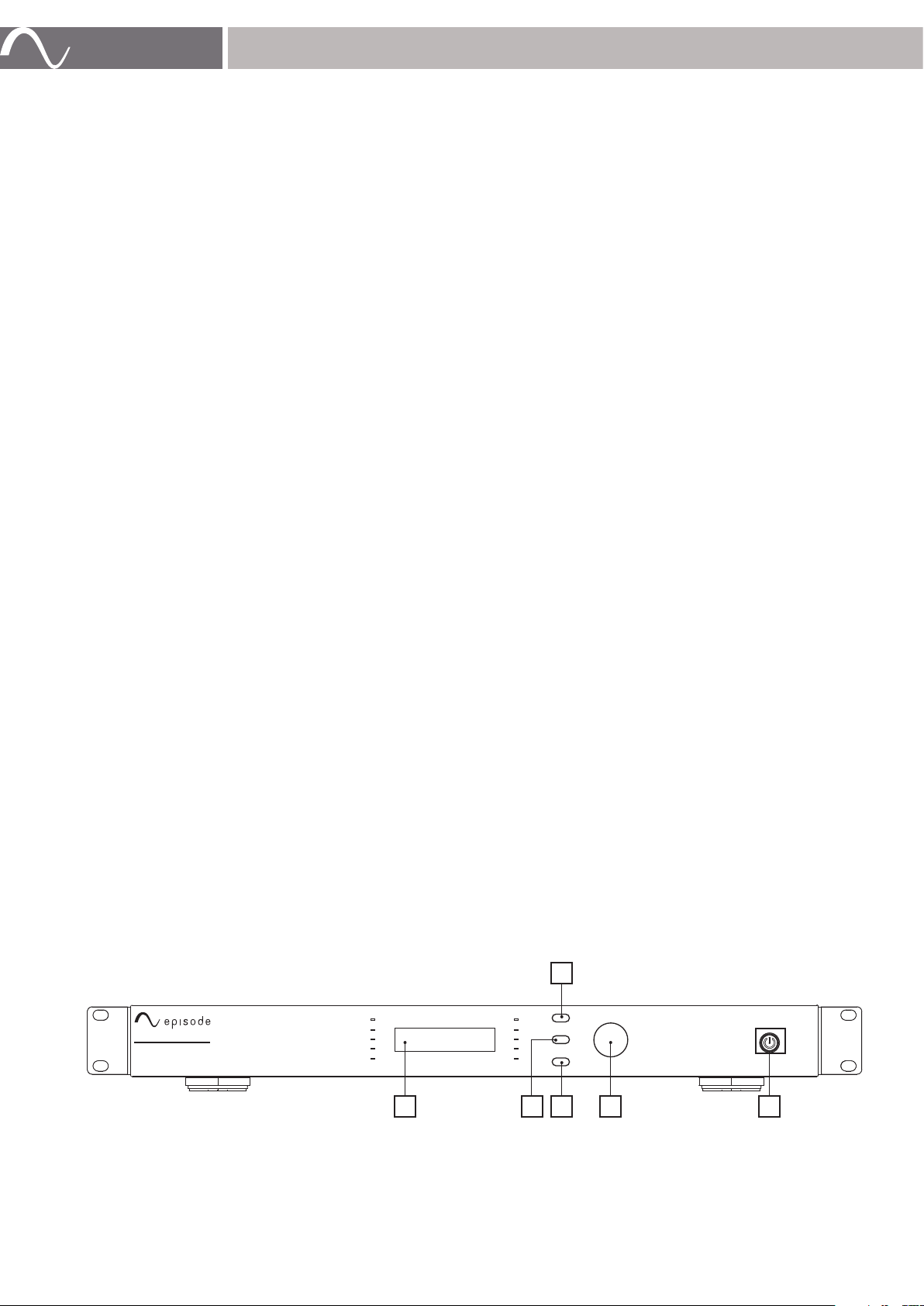
FRONT PANEL
B
A. Display Panel
Displays system information.
B. Channel Select
Press to select the input channel.
PROTECT
SIGNAL
CH1
PROTECT
SIGNAL
CH2
CLIP
CH.SEL
-10
-20
MENU
ADJUST | SET
BACK
DC F
E
www.snapav.com Support 866.838.5052
www.snapav.com Support 866.838.5052
EA-AMP-HYB-2D-1000
CLIP
-10
-20
A
Page 7
C. Menu Select
Press to cycle through system menus.
D. Back Button
Press to navigate back a step in the system menu.
E. Level Adjustment/Selection Knob
Turn to adjust system levels, press to select.
F. Power Switch with LED Indicator
Momentary switch for manual control of standby power mode.
BLUE – On
RED – Standby
NOTE: Download the Menu Function chart on the Product Support tab for a complete menu map.
REAR PANEL
B C J K
page | 7
SPEAKER OUT
IN
CH2 CH1
OUT
BRIDGE
A
T
TENTION ! RISQUE DE CHOC ! ÉLECTRIQUE P
DO NOT OPEN!
AS OUVRIR !
!
RISK OF ELECTRICAL SHOCK!
CAUTION
C UL
LIFTED
U
L
118V110-120V AC-60H-230W
230V230-240AC-50Hz-230W
ON
OFF
230V FUSE T4A H250V
110 V FUSE T8AH 250V
Use only a 250V fuse
Employer uniquement aux
un fusible de 250V
LD FE
NETWORK
CONTROL
LINK ACT
A
SERIAL
CONTROL
TRIGGER
DC 12 V
IN
LINE IN
CH2
OUT
CH1
CH1
CH2
CH1
LINE OUT
CH2
CH2
DIGITAL
CH1
G H I
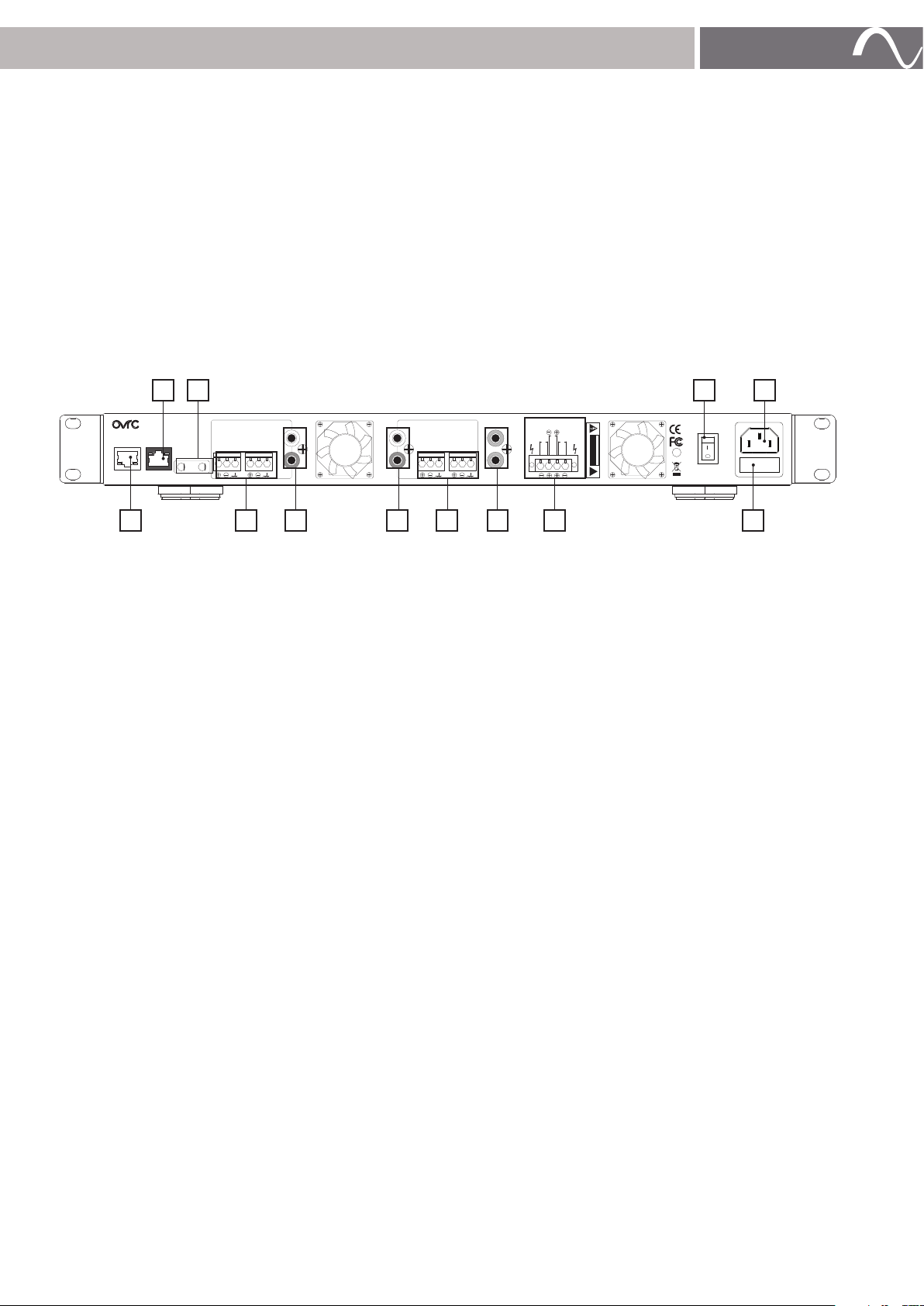
A. Ethernet port
RJ45 port for connecting an Ethernet Cat5e/6 cable for IP control of the amplifier.
B. RS-232
To communicate with a control system or PC for serial control of the amplifier.
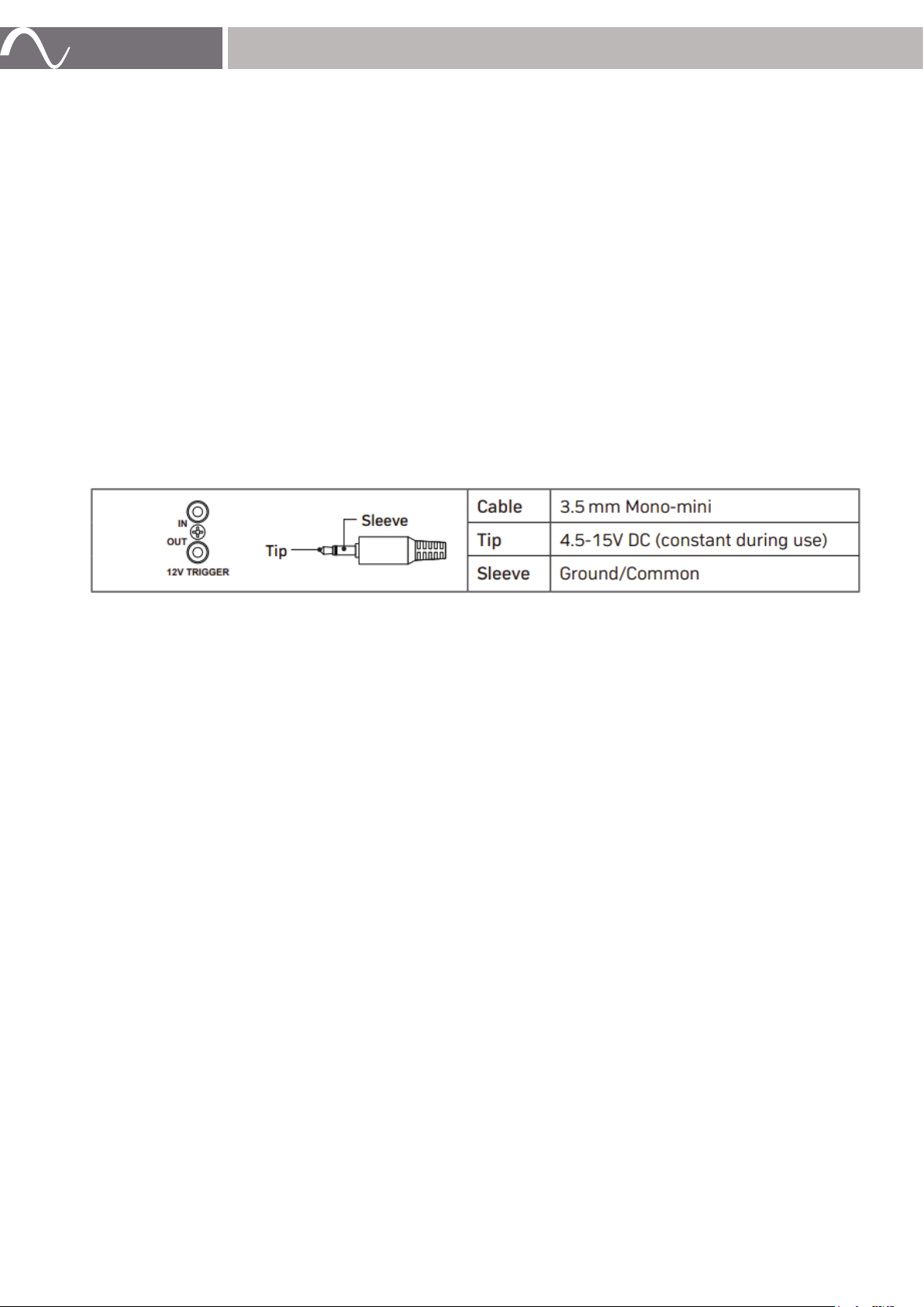
C. 12V Trigger IN and OUT
When 4.5-15V DC are applied to 12V IN, amplifier will turn on. When voltage is dropped, amplifier
turns back off. 12V OUT allows other equipment to be controlled from the same 12V signal.
D. Balanced Inputs 1 & 2
Set-screw connections for sources with balanced output.
E. Unbalanced Inputs 1 &2
Unbalanced RCA input connections for connection of sources.
F. Unbalanced Loop Out 1 & 2
Unbalanced RCA loop out for connection to other amplifiers.
G. Balanced Loop Out 1 & 2
Set-screw balanced loop out for connection to other amplifiers.
H. Digital Input/Output ports
Digital input and output ports for digital sources.
I. Speaker terminals
Note proper positive and negative connections for operating in bridge mode .
J. Power Switch
Main amplifier power switch.
K. IEC power cord
Detachable power for amplifier.
L. AC fuse
Replaceable main power fuse
© 2021 Wirepath Home Systems, LLC
Page 8
page | 8
SOURCE CONNECTIONS
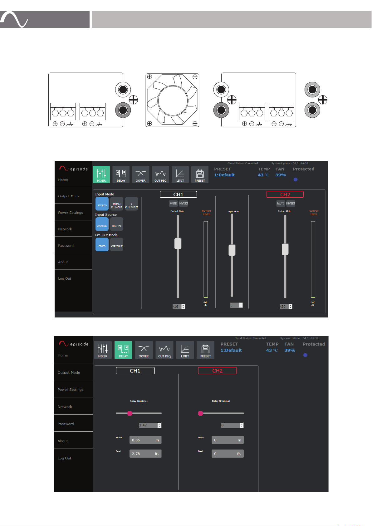
Balanced and unbalanced connections are available as shown below. Line out connections may be used
to send audio signals to other equipment.
DIGITAL
IN
OUT
CH2
LINE IN
CH1
CH1
CH2
CH1
CH2
LINE OUT
CH2
CH1
Input mode, source, pre-out, and gain adjustments can all be made via the GUI home screen. Please note
that input gain is only adjustable on the analog input source.
Sliding and precise delay adjustment is also available by channel via the home setup screen.
www.snapav.com Support 866.838.5052
www.snapav.com Support 866.838.5052
Page 9
page | 9
SPEAKER OUT
INPUT GAIN
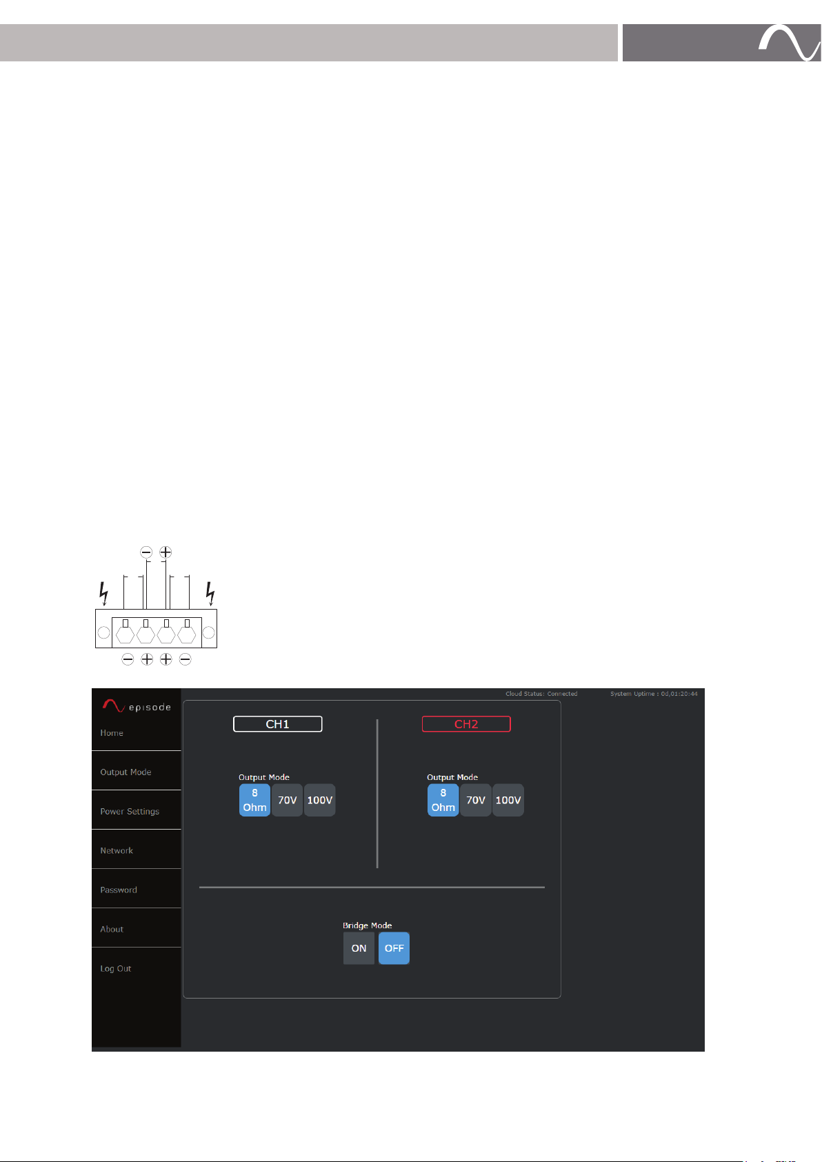
The Episode Hybrid amplifier is optimized for peak performance when the input voltage of the source
is 1.4V. To help you achieve that number, the Hybrid amp includes a pre-amplified stage to modify the
input source voltage. If the input voltage from the source is less than 1.4V, maximum power output from
the amplifier cannot be achieved and the speakers may sound under powered, or quieter than expected.
Adjust the Input Gain to get your source’s output voltage as close to 1.4V as possible.
Use the
it does not clip, or the level turn red. It important to determine how volume is being controlled for the zone
in which the hybrid amplifier is being used. There are two common use cases for this amplifier.
•
•
Input Gain slider to boost the input voltage of your source and watch the Output Level to make sure
Using the amplifiers output gain for volume control: This is the recommended configuration. Fix the
volume of the source and use the amplifier’s controls for volume adjustment. This allows for optimal
performance and a more granular adjustment to the zones volume. The goal is to make sure your
Output Level doesn’t clip when your amplifier is at peak volume.
Using the Source output for volume control: By using this method you are dynamically changing the
source’s output voltage being input to the amplifier. With this setup, the scale and granularity of
volume control is dependent on the source being used. The goal is to make sure your Output Level
doesn’t clip when your source is at peak volume.
NOTES:
The output volume of the amplifier must be fixed for this configuration.
For detailed videos for setting input and output gain, see the Hybrid amp product pages on SnapAV.com.
See the EA-AMP-HYB Amplifier Source Output Chart to help you determine necessary adjustments.
SPEAKER CONNECTIONS AND OUTPUT MODE
BRIDGE
CH2 CH1
Use 14 or 16 gauge stranded two-conductor speaker wire. Connect the
appropriate conductor to each screw terminal, observing correct polarity.
Bridged markings are also shown to the left. Use burial rated wire as necessary
for outdoor applications.
© 2021 Wirepath Home Systems, LLC
Page 10
page | 10
AMPLIFIER POWER CONTROL
Front Panel Power Button
When the amplifier is powered on, the power swoosh illuminate solid blue. When it is in Standby, the
power button is red.
Resetting the Amplifier
Press and hold the BACK button for 10 seconds after the receiver is powered on for a “soft” reset. This
resets login information.
Press and hold the BACK button for 20 seconds to initiate a factory reset. The front panel lights will flash,
indicating the reset is in progress. This will reset all settings including DSP, channel levels, and input
names.
12V Trigger
Episode Hybrid amplifiers are equipped with 12V DC trigger inputs and outputs for trigger control and
daisy chain control of more than one amplifier.
To utilize the 12V DC trigger function, attach a mono mini cable between the 12V trigger output of the
controlling device and the 12V DC TRIGGER IN port of the amplifier. Connect other devices to the TRIGGER
OUT port on the amplifier using a mono-mini cable.
Audio Sense
If Audio Sense is enabled via setup through the web interface, the amplifier turns on when an audio signal
is detected. The unit enters standby mode if no signal is detected after 15 minutes.
Power State
Deep vs. Light Sleep – Deep sleep is required only to meet EU standards for low power consumption
when the amplifier is not operational. It is not enabled out of the box.
VOLUME CALIBRATION
To calibrate source input gain and the inline volume control level:
1. Connect all speaker and audio source wiring, then connect power to the amplifier.
2. Set all volume controls to their maximum volume setting (if applicable).
3. Set each output level adjustment knob to 50% and set the input level for unused channels to minimum.
4. Power on the amplifier and input source, then play audio typical of what will be played in the area.
5. Set the source volume level to half. If the audio becomes distorted, turn the volume down until audio
sounds clear.
6. Set the level adjustment for the area to a level where the volume is slightly above normal listening
level. If the audio becomes distorted, experiment with changes to the source volume and the LEVEL
adjustment knob until audio sounds clear.
www.snapav.com Support 866.838.5052
www.snapav.com Support 866.838.5052
Page 11
COMMON DEVICE SETUPS AND STEPS FOR CALIBRATING VOLUME:
Triad Audio Matrix to Analog Input:
1. If you are using the Triad Matrix for volume control:
• In the Hybrid amp, set the volume to 0 on both channels.
• Turn on the zone and play music at 85-90% (volume is expected to be low because your amp
volume is at 0).
• In the Hybrid amp, raise the volume on both channels until you find a level that should be the max.
• If you are maxed out on the output level, then turn the gain up on the Hybrid amp. Gain from 3 to
5 works well when used with a Triad Matrix, but this will vary by device.
2. If you are using the Hybrid amp for volume control:
• Set the Triad Matrix for 75-80% fixed output for the zone. Turn off loudness boost if it is on.
• In the Control4 driver for the Hybrid amp, make sure you have Ch linking set up. This will allow
Control4 to control CH1, and the Hybrid amp will link Ch2 and keep its ratio difference. For example,
if Ch1 is set to +5 steps, it will always be 5 steps higher than Ch2.
• Adjust the Hybrid amp while playing music to test the level offset between channels.
• When the Hybrid amp is maxed out, adjust gain, as needed. Gain should not exceed 7.
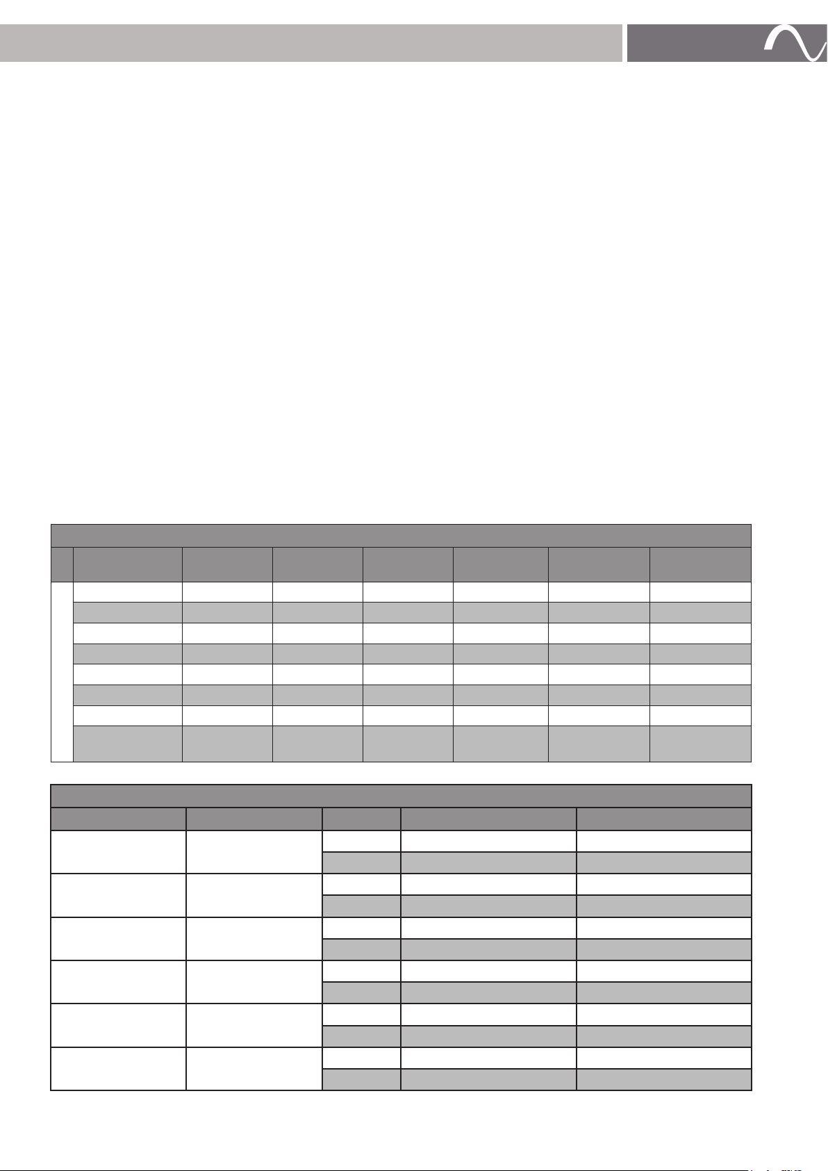
SPEAKER PRESETS
page | 11
Amplifiers come with a preloaded bank of presets noted in the table below. This includes full system
presets and DSP settings for any landscape speaker when used in combination with ES-LS-BSUB-12 or
ES-LS-HSUB-10.
CAUTION: When using the provided presets below, the subwoofer must be connected to Channel 1.
CHANNEL 2
LS-SAT-4
(70V)
LS-SAT-4 (70V) (2) LS4SATS
LS-SAT-6 (70V) (3) LS6SATS
LS-SAT-8 (70V) (4) LS8SATS
LS-SAT-4 (8Ω) (17) LS4SAT_8
LS-SAT-6 (8Ω) (18) LS6SAT_8
LS-SAT-8 (8Ω) (19) LS8SAT_8
CHANNEL 1
LS-HSUB-10 (8Ω) (5) ST4_HS10 (6) ST6_HS10 (7) ST8_HS10 (8) S4HS10_8 (9) S6HS10_8 (10) S8HS10_8
LS-BSUB-12 (8Ω) (11) ST4_
SB12
LS-SAT-6
(70V)
(12) ST6_
SB12
LS-SAT-8
(70V)
(13) ST8_
SB12
LS-SAT-4 (8Ω) LS-SAT-6 (8Ω) LS-SAT-8 (8Ω)
(14) S4SB12_8 (15) S6SB12_8 (16) S8SB12_8
PRESETS ON UNIT OUT OF BOX
Preset# Preset Name Channel Output Voltage Speaker Hookup
1
2
3
4
5
6
Default
LS4SATS
LS6SATS
LS8 SATS
ST4_HS10
ST6_HS10
1
2
1 70V SAT 4
2 70V SAT 4
1 70V SAT 6
2 70V SAT 6
1 70V SAT 8
2 70V SAT 8
1
2 70V SAT 4
1
2 70V SAT 6
8Ω Flat
8Ω Flat
8Ω HARDSCAPE 10”
8Ω HARDSCAPE 10”
© 2021 Wirepath Home Systems, LLC
Page 12
page | 12
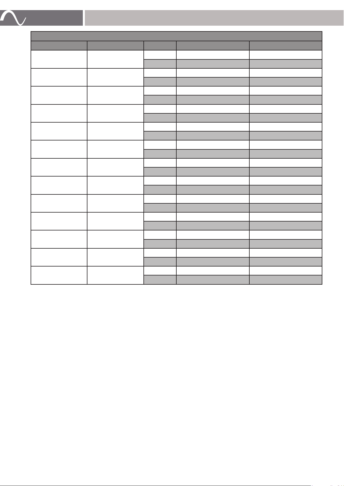
PRESETS ON UNIT OUT OF BOX
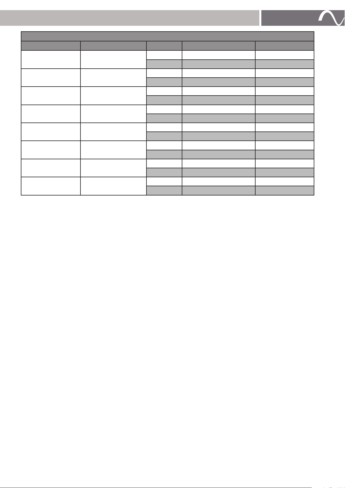
Preset# Preset Name Channel Output Voltage Speaker Hookup
7
8
9
10
11
12
13
14
15
16
17
18
19
ST8_HS10
S4HS10_8
S6HS10_8
S8HS10_8
ST4_SB12
ST6_SB12
ST8_SB12
S4SB12_8
S6SB12_8
S8SB12_8
LS4SAT_8
LS6SAT_8
LS8SAT_8
1
2 70V SAT 8
1
2 8Ω SAT 4
1
2 8Ω SAT 6
1
2 8Ω SAT 8
1
2 70V SAT 4
1
2 70V SAT 6
1
2 70V SAT 8
1
2 8Ω SAT 4
1
2 8Ω SAT 6
1
2 8Ω SAT 8
1
2 8Ω SAT 4
1
2 8Ω SAT 6
1
2
8Ω HARDSCAPE 10”
8Ω HARDSCAPE 10”
8Ω HARDSCAPE 10”
8Ω HARDSCAPE 10”
8Ω BURIAL 12”
8Ω BURIAL 12”
8Ω BURIAL 12”
8Ω BURIAL 12”
8Ω BURIAL 12”
8Ω BURIAL 12”
8Ω SAT 4
8Ω SAT 6
8Ω SAT 8
8Ω SAT 8
Using Presets with the Local Display
1. Press the Menu button on the front of the amplifier.
2. Rotate the Adjust/Set knob until you see Menu Preset, then press the knob.
3. Rotate the Adjust/Set knob until you see the desired preset on the display panel, then press the
knob. The preset name will appear with LOAD underneath.
4. Press the Adjust/Set knob once more, and the amplifier loads the preset from its memory.
Using Presets in the Web Interface
1. Click the Preset button at the top of the page.
2. Select the preset from the Select Preset drop-down list.
3. Click Load Preset.
www.snapav.com Support 866.838.5052
www.snapav.com Support 866.838.5052
Page 13
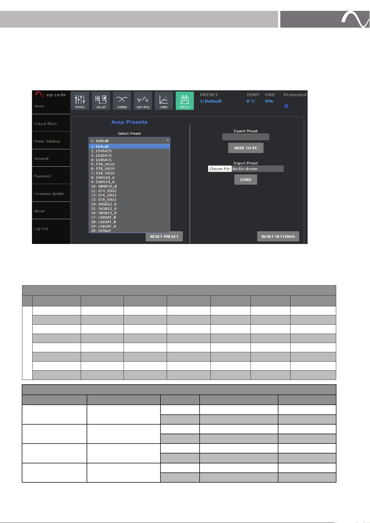
Loading Preset Files
1. Click Import Preset to load a preset file.
2. Refresh the page for the new presets to appear under the Select Preset drop-down list.
NOTE: Loading a preset file erases the current preset listings. Click Reset Presets to restore the
amplifier’s default presets.
page | 13
Additional Preset Files
To mix different LS-SAT models between channel 1 and 2, see the preset configuration table below. The
Preset Group B files can be found on the product’s Support tab.
CHANNEL 2
LS-SAT-4 (70V) LS-SAT-6 (70V) LS-SAT-8 (70V) LS-SAT-4 (8Ω) LS-SAT-6 (8Ω) LS-SAT-8 (8Ω)
LS-SAT-4 (70V) (2) LS MIX4_6
LS-SAT-6 (70V) (3) LS MIX4_8
LS-SAT-8 (70V) (4) LS MIX6_8
LS-SAT-4 (8Ω)
LS-SAT-6 (8Ω)
LS-SAT-8 (8Ω)
CHANNEL 1
LS-BSUB-12 (8Ω)
LS-BSUB-10 (8Ω)
PRESET GROUP B
Preset# Preset Name Channel Voltage Speaker Hookup
1
2
3
4
Default
LS MIX4_6
LS MIX4_8
LS MIX6_8
1 8Ω Flat
2 8Ω Flat
1 70V SAT 4
2 70V SAT 6
1 70V SAT 4
2 70V SAT 8
1 70V SAT 6
2 70V SAT 8
© 2021 Wirepath Home Systems, LLC
Page 14
page | 14
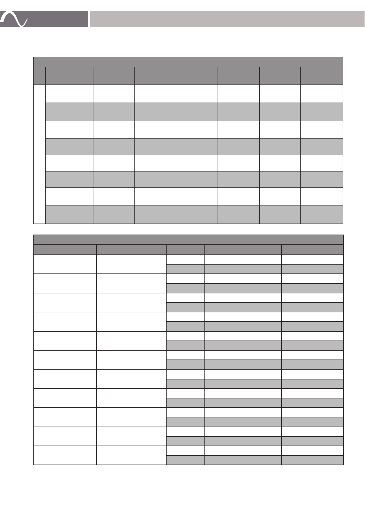
To use any landscape speaker and ES-LS-BSUB-8 or ES-LS-BSUB-10, see the configuration table below.
The Preset Group C file can be found on the product’s Support tab.
CHANNEL 2
LS-SAT-4
(70V)
LS-SAT-6
(70V)
LS-SAT-8
(70V)
LS-SAT-4 (8Ω)
LS-SAT-6 (8Ω)
CHANNEL 1
LS-SAT-8 (8Ω)
LS-BSUB-8
(8Ω)
LS-BSUB-10
(8Ω)
LS-SAT-4
(70V)
(2) LS4SATS
(5) ST4_SB8 (6) ST6_SB8 (7) ST8_SB8 (8) S4SB8_8 (9) S6SB8_8 (10) S8SB8_8
(11) ST4_
SB10
LS-SAT-6
(70V)
(3) LS6SATS
(12) ST6_
SB10
LS-SAT-8
(70V)
(4) LS8SATS
(13) ST8_
SB10
LS-SAT-4
(8Ω)
(17)
LS4SAT_8
(14)
S4SB10_8
LS-SAT-6
(8Ω)
(18)
LS6SAT_8
(15)
S6SB10_8
LS-SAT-8
(8Ω)
(19)
LS8SAT_8
(16)
S8SB10_8
PRESET GROUP C
Preset# Preset Name Channel Output Voltage Speaker Hookup
1
2
3
4
5
6
7
8
9
10
11
Default
LS4SATS
LS6SATS
LS8 SATS
ST4_SB8
ST6_SB8
ST8_SB8
S4SB8_8
S6SB8_8
S8SB8_8
ST4_SB10
1 8Ω Flat
2 8Ω Flat
1 70V SAT 4
2 70V SAT 4
1 70V SAT 6
2 70V SAT 6
1 70V SAT 8
2 70V SAT 8
1 8Ω BURIAL 8”
2 70V SAT 4
1 8Ω BURIAL 8”
2 70V SAT 6
1 8Ω BURIAL 8”
2 70V SAT 8
1 8Ω BURIAL 8”
2 8Ω SAT 4
1 8Ω BURIAL 8”
2 8Ω SAT 6
1 8Ω BURIAL 8”
2 8Ω SAT 8
1 8Ω BURIAL 10”
2 70V SAT 4
www.snapav.com Support 866.838.5052
www.snapav.com Support 866.838.5052
Page 15
page | 15
PRESET GROUP C
Preset# Preset Name Channel Output Voltage Speaker Hookup
12
13
14
15
16
17
18
19
ST6_SB10
ST8_SB10
S4SB10_8
S6SB10_8
S8SB10_8
LS4SAT_8
LS6SAT_8
LS8SAT_8
1 8Ω BURIAL 10”
2 70V SAT 6
1 8Ω BURIAL 10”
2 70V SAT 8
1 8Ω BURIAL 10”
2 8Ω SAT 4
1 8Ω BURIAL 10”
2 8Ω SAT 6
1 8Ω BURIAL 10”
2 8Ω SAT 8
1 8Ω SAT 4
2 8Ω SAT 4
1 8Ω SAT 6
2 8Ω SAT 6
1 8Ω SAT 8
2 8Ω SAT 8
© 2021 Wirepath Home Systems, LLC
Page 16
page | 16
TROUBLESHOOTING
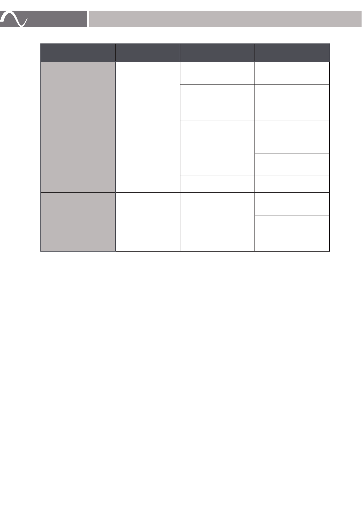
Scenario Indicator Possible Causes/
Going into Protection
No output
Red Protect LED
Blinking
Red Protect LED Solid
Level Meter (LEDs,
WebUI)
Check Points
High Temperature.
High Current (exceed
rated power) causes
‘speaker protect limiter’
to activate, which reduces
power.
Firmware is updating (2
Channel blinking)
Speaker Terminal Short
(Channel 2 will light up if
either terminal detects a
short).
Failure to jump to partition
after firmware update.
If Level Meter (Green LED)
illuminates, then source
audio is being sent to the
amp.
If the Level Meter in the
Web UI is responsive ,
then source audio is being
sent to amp.
Resolution
Self heals: Allow unit
to cool down to restore
normal conditions.
Self-heals: Reduce input
music level to release
internal limiter.
N/A - Allow update to
finish.
Ensure speaker terminal
is fully connected.
Remove speaker terminal,
if red light is still solid investigate further.
Contact Tech Support for
firmware recovery.
Ensure speaker output
is configured correctly.
(Speaker out).
If Level Meter shows
audio response but still
no audio, ensure source
inputs are configured
correctly.
Distorted Audio at Normal Volume
If the LEVEL adjustment for a zone is set too high to compensate for low source volume, distortion can
occur in the form of background noise or poor audio quality. This will be heard as a steady hissing or
humming behind music, clipping of signal, or distortion of highs and lows.
To eliminate this issue, re-adjust the volume levels by starting at baseline settings and re-adjusting the
final volume so that a maximum comfortable volume level can be reached with no distortion, while using
the source volume or inline control.
Inline Volume “Thump”
If you hear a “thumping” sound, the amplifier and source volume levels are set too high. Inline volume
controls should be calibrated so that they are one or two adjustment levels away from their maximum
setting when audio is at the normal listening level. This will leave one to three settings above normal level
for use if a little extra volume is needed.
www.snapav.com Support 866.838.5052
www.snapav.com Support 866.838.5052
Page 17
SPECIFICATIONS
page | 17
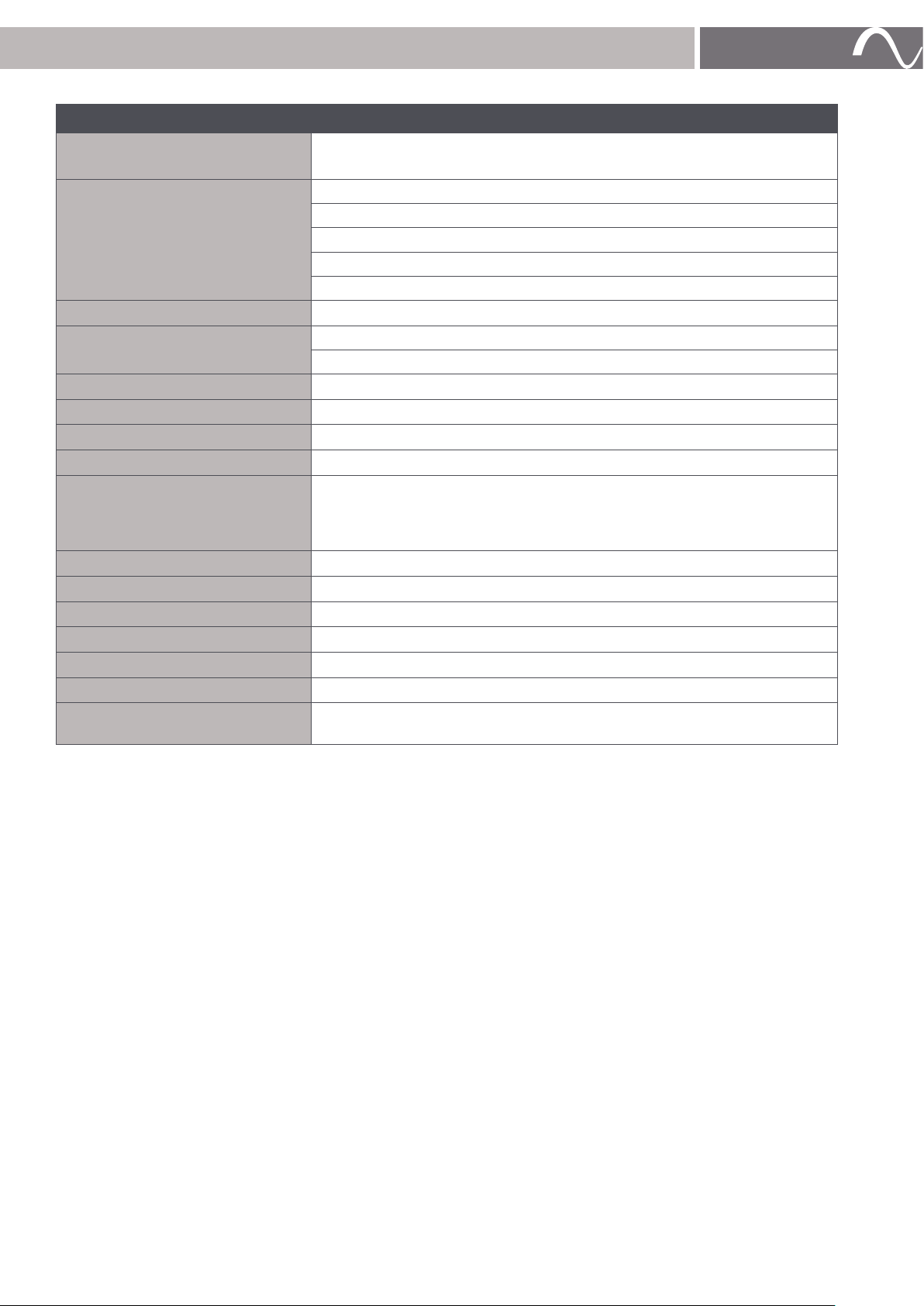
EA-AMP-HYB-2D-1000
Channels
Power Output
Input Sensitivity
Input Impedance
Signal-to-Noise Ratio
Total Harmonic Distortion (THD)
Frequency Response
Inputs
Audio Inputs/Outputs
12 Volt Trigger
Dimensions (WxHxD)
Rack Spacing
Input Voltage
Weight
Certification
AC Power Consumption
2-channel
300W per channel @ 8 ohm (1000W bridged)
500W per channel @ 4 ohm (2000W bridged)
700W per channel @ 2 ohm
500W per channel @ 70V
500W per channel @100V (230V AC only)
1.4 Vrms, max power
RCA analog input: 10kΩ
Balanced analog input: 20k Ω
101 dB A-weighted @ 1.4 Vms & 4Vms input max
Less than 1%
± 2d B at ⅛ power (20 Hz to 20 kHz)
Network: RJ45 jack, 10/100 Mbps
Bal. Analog Audio: 2 × 3-post Phoenix-style pluggable screw terminal block
Analog RCA: White jack (L. ch), Red jack (R. ch)
Spkr. Output: 2 × 3 post Phoenix-style pluggable screw terminal block (12-
18 AWG)
3.5 mm mono jack
431.8 mm (17”) x 43.942 mm (1.73”) x 355.6 mm (14”)
1U
115V AC / 230V AC
5.44 kg (12 lb)
Meets FCC Part 15, UL EN60065
230W typical
1100W max
LEGAL NOTICES AND WARRANTY
Find details of the product’s Limited Warranty at snapav.com/warranty or request a paper copy from
Customer Service at 866.424.4489. Find other legal notices, such as regulatory, safety, and patent, at
snapav.com/legal.
CONTACTING TECHNICAL SUPPORT
866.838.5052
[email protected]
Copyright ©2021, Wirepath Home Systems, LLC. All rights reserved. Control4 and SnapAV and their respective logos are registered
trademarks or trademarks of Wirepath Home Systems, LLC, dba “Control4” and/or dba “SnapAV” in the United States and/or other
countries. 4Store, 4Sight, Control4 My Home, Snap AV, Araknis Networks, BakPak, Binary, Dragonfly, Episode, Luma, Mockupancy,
Nearus, NEEO, Optiview, OvrC, Pakedge, Sense, Strong, Strong Evolve, Strong Versabox, SunBriteDS, SunBriteTV, Triad, Truvision,
Visualint, WattBox, Wirepath, and Wirepath ONE are also registered trademarks or trademarks of Wirepath Home Systems, LLC.
Other names and brands may be claimed as the property of their respective owners. All specifications subject to change without
notice.
© 2021 Wirepath Home Systems, LLC
Page 18

page | 18
www.snapav.com Support 866.838.5052www.snapav.com Support 866.838.5052
Page 19

page | 19
© 2021 Wirepath Home Systems, LLC
Page 20

© 2021 Wirepath Home Systems, LLC
EA-AMP-HYB-2D-X000_Manual-B 20210407MS
 Loading...