

Page 1
FusionPro 32/48
Laser System Manual | Model 16000
Original Instructions
Register your system now for driver update notifications
and FREE files! EPILOGLASER.COM/REGISTER
Technical Support: +1 (303) 215-9171
Knowledge Base: support.epiloglaser.com
System Registration: epiloglaser.com/register
Driver/Firmware: epiloglaser.com/fusionpro-drivers
UPDATED APRIL 2019 | EPILOGLASER.COM/MANUALS
Page 2

Page 3

TABLE OF CONTENTS
FIRE WARNING 1
INTRODUCTION 2
How to Use This Owner’s Manual .............................................................................................................................................. 2
Icons Used in this Manual ............................................................................................................................................................... 2
SECTION 1: SAFETY 3
Laser Safety .............................................................................................................................................................................................. 3
Electrical Safety ..................................................................................................................................................................................... 3
Safety Features and Regulatory Compliance ................................................................................................................. 4
Dos and Don’ts ..................................................................................................................................................................................... 10
SECTION 2: GETTING STARTED 11
1. Unpacking the Laser System ................................................................................................................................................... 12
2. Choose Where to Locate the System ...............................................................................................................................14
3. Connecting the Exhaust ............................................................................................................................................................. 15
4. Connecting Electrical Power...................................................................................................................................................17
5. Connect the Laser to Your Computer .............................................................................................................................. 17
6. Set the Fusion Pro’s IP Address ..............................................................................................................................................18
7. Sign Up for Driver Updates and Register Your System ........................................................................................19
SECTION 3: SOFTWARE INSTALLATION 21
Epilog Job Manager Instructions ............................................................................................................................................. 21
Uninstalling the Previous Job Manager ..............................................................................................................................21
Windows 7: Ethernet Installation .............................................................................................................................................. 23
How to Install the Epilog Job Manager ..............................................................................................................................25
Troubleshooting the Job Manager ......................................................................................................................................... 31
Important Job Manager Notes .................................................................................................................................................32
SECTION 4: THE JOB MANAGER 33
Using the Epilog Job Manager..................................................................................................................................................33
Printing to the Epilog Job Manager ......................................................................................................................................34
Organizing Your Print Jobs ..........................................................................................................................................................34
Previewing Your Job .........................................................................................................................................................................38
Searching for a Job ..........................................................................................................................................................................38
Finding Job History ............................................................................................................................................................................ 39
Vector Sorting ...................................................................................................................................................................................... 40
Material Settings Tab .......................................................................................................................................................................41
Job Settings Tab .................................................................................................................................................................................44
Changing Program Settings ........................................................................................................................................................46
SECTION 5: THE LASER DASHBOARD 47
Setting Up CorelDRAW for the Laser .....................................................................................................................................48
Sending Your First Project .............................................................................................................................................................49
Presetting Your Cut Lines .............................................................................................................................................................. 52
Placing Your Artwork .......................................................................................................................................................................52
Dividing Your Job Into Processes ............................................................................................................................................ 53
Editing Artwork with Live View ................................................................................................................................................... 59
Saving Your Settings.........................................................................................................................................................................62
File Settings .............................................................................................................................................................................................63
Settings in Detail .................................................................................................................................................................................64
Processes Tab .......................................................................................................................................................................................66
Advanced Tab ...................................................................................................................................................................................... 67
Notes Tab ................................................................................................................................................................................................. 67
File Setup FAQs .....................................................................................................................................................................................68
Additional CorelDRAW Laser Dashboard Features ....................................................................................................68
SECTION 6: CONTROL PANEL 71
Display ......................................................................................................................................................................................................... 71
- i -
Page 4

TABLE OF CONTENTS
Joystick ...................................................................................................................................................................................................... 77
Job Storage ............................................................................................................................................................................................ 77
SECTION 7: QUICK START GUIDE 79
Artwork Setup ........................................................................................................................................................................................ 79
Setting a Vector Cutting Line .................................................................................................................................................... 80
Resolution ..................................................................................................................................................................................................81
Landscape or Portrait .....................................................................................................................................................................83
SECTION 8: SYSTEM FEATURES 85
IRISTM Camera Positioning System ..........................................................................................................................................85
Touch Screen .........................................................................................................................................................................................85
Air Assist ....................................................................................................................................................................................................86
Auto Focus vs Manual Focus ......................................................................................................................................................86
Key Switch ................................................................................................................................................................................................ 87
Image Dithering ...................................................................................................................................................................................87
Color Mapping ......................................................................................................................................................................................89
Using Color Mapping .......................................................................................................................................................................89
Red Dot Pointer ....................................................................................................................................................................................93
Emergency Stop Button .................................................................................................................................................................94
Front Access Door ..............................................................................................................................................................................94
Task Plate/Vacuum Hold-Down Table .................................................................................................................................94
Exhaust Plenum ....................................................................................................................................................................................95
SECTION 9: OPTIONAL FEATURES 97
Vector Cutting Table/Vacuum Hold-Down Table ........................................................................................................ 97
PhotoLaser Plus ....................................................................................................................................................................................98
SECTION 10: ENGRAVING MATERIALS 105
CO2 Laser Materials/Techniques ......................................................................................................................................... 105
SECTION 11: SPECIFICATIONS 115
Fusion Pro Laser Technical Specifications ....................................................................................................................... 115
Compatibility ........................................................................................................................................................................................ 116
Recommended PC ............................................................................................................................................................................ 116
About The CO2 Laser Source ......................................................................................................................................................117
Federal Communications Commission (FCC) Notice ................................................................................................ 118
SECTION 12: TECHNICAL SUPPORT 119
Contacting Technical Support ................................................................................................................................................. 119
Frequently Asked Questions .................................................................................................................................................... 120
Join Epilog Laser’s Online Community ................................................................................................................................122
SECTION 13: MATERIAL SUPPLIERS 123
Industry Material Supplier List ................................................................................................................................................. 123
APPENDIX A: WARRANTY STATEMENT 127
Warranty Statement for the Fusion Pro Laser ...............................................................................................................127
APPENDIX B: MATERIAL SETTINGS 129
Fusion Pro Suggested Material Settings (CO2) ............................................................................................................. 129
APPENDIX C: SYSTEM CALIBRATION 133
Camera Calibration ........................................................................................................................................................................ 136
INDEX 141
- ii -
Page 5

FIRE WARNING
Fire Warning
Your laser system uses a high intensity beam of light that can generate extremely high
temperatures when it comes into contact with the material being engraved, marked or
cut. Some materials are extremely flammable and can easily ignite and burst into open
flame setting the machine afire. This open flame is very dangerous and has the potential to
destroy not only the machine, but the building in which it is housed.
Experience shows that vector cutting with the laser has the most potential to create an open flame.
Many materials are susceptible to igniting, but acrylic, in all its dierent forms, has been shown to be
especially flammable when vector cutting with the laser.
Please read the following warnings and recommendations and follow them closely at all times!
• Stay with the laser. Never operate the laser system while unattended.
• Keep the area clear. Clean around the machine and keep the area free of clutter, combustible
materials, explosives, or volatile solvents such as acetone, alcohol, or gasoline.
• Be prepared with a fire extinguisher. Always keep a properly maintained and inspected fire
extinguisher on hand. Epilog recommends a Halotron fire extinguisher or a multi-purpose dry
chemical fire extinguisher. The Halotron extinguishers are more expensive than a dry chemical, but
oer certain advantages should you ever need to use an extinguisher. The Halotron extinguisher
discharges a clean, easily removable substance that is not harmful to the mechanics or wiring of
the laser system. The dry chemical extinguisher discharges a sticky, corrosive powder that is very
diicult to clean up.
• Use Air Assist. Always use the system’s Air Assist feature when vector cutting.
• Use caution when vector cutting. Many materials have the potential to suddenly burst into flames
when cut with a laser – even materials that may be very familiar to the user. Always monitor the
machine when it is operating.
• Clean the laser. A buildup of cutting and engraving residue and debris is dangerous and can
create a fire hazard in its own right. Keep your laser system clean and free of debris. Regularly clean
underneath the Vector Cutting Table to clean any small pieces that have fallen through the grid.
- 1 -
Page 6
INTRODUCTION
How to Use This Owner’s Manual
Thank you for purchasing an Epilog Fusion Pro Laser system. Your Epilog system has been designed to
be easy to operate, but you will utilize it to its fullest potential by taking some time to read this owner’s
manual prior to use. You will be ready to use the Epilog Laser system as soon as you read the first few
sections. Then you can refer to topics in the remaining sections, as you work.
Icons Used in this Manual
Look for these symbols to help you find valuable information throughout the text:
Helpful notes to keep in mind when running the laser!
This icon signifies advice you can try that will save you significant time.
This icon highlights current contact information for receiving help.
Warnings and cautions to keep in mind when running the laser.
This icon indicates the potential for fire damage when operating the laser.
- 2 -
Page 7

SECTION 1: SAFETY
Laser Safety
The standard reference for laser safety is the American Standard for the Safe Use of Lasers, Z136.1-2000,
developed by the American National Standards Institute (ANSI). This reference is the basis for many of
the federal regulations for laser and laser system manufacturers, and for the Occupational Safety and
Health Administration (OSHA) laser safety guidelines. It contains detailed information concerning proper
installation and use of laser systems.
While the ANSI standard itself does not have the force of law, its recommendations, including warning
signage, training, and the designation of a laser safety oicer, may be compulsory under local workplace
regulations when operating laser systems above Class I. It is the operator’s responsibility to ensure that
the installation and operation of the Epilog Model 16000 Laser System is peormed in accordance with
all applicable laws.
Copies of ANSI Standard Z136.1-2000 are available from Epilog Corporation or from:
Laser Institute of America
12424 Research Parkway, Suite 125
Orlando, FL 32826
(407) 380-1553
Electrical Safety
The AC input power to the Epilog Model 16000 Laser System is potentially lethal and is fully contained
within the cabinet.
• DO NOT open any of the machine’s access panels while the unit is plugged in.
Opening a panel may expose the operator to the unit’s AC input power.
• DO NOT make or break any electrical connections to the system while the unit is
turned on.
Fusion Pro Electrical Specifications
Model Wattage(s) Voltage Amp draw-MAX
Pro 32 50, 60, 80 120 13A
Pro 32 50, 60, 80 240 6.5A
Pro 32 120 240 10A
Pro 48 50, 60, 80 240 6.5A
Pro 48 120 240 10A
- 3 -
Page 8
SECTION 1: SAFETY
Safety Features and Regulatory Compliance
Epilog has incorporated specific safety features into the Model 16000 Laser System in order to meet the
requirements of 21 CFR 1040 and the International Standard IEC 60825-1. These safety features include:
• A safety enclosure (cabinet), which fully encloses the engraving laser and its beam path.
• Dual redundant interlock systems that turn o the engraving laser when the window is opened.
• A visible emission indication when the Laser Diode Pointer (Red Dot Pointer) is operating. There is an
LED indicator on the machine’s front panel.
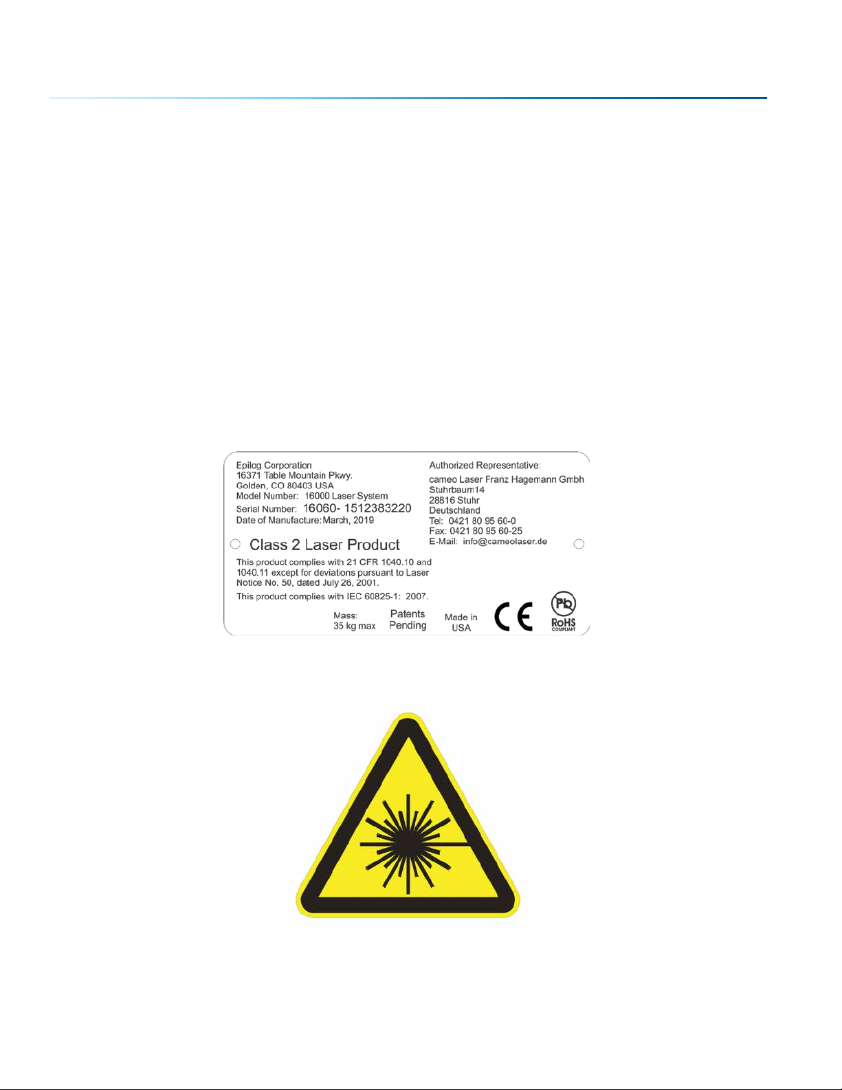
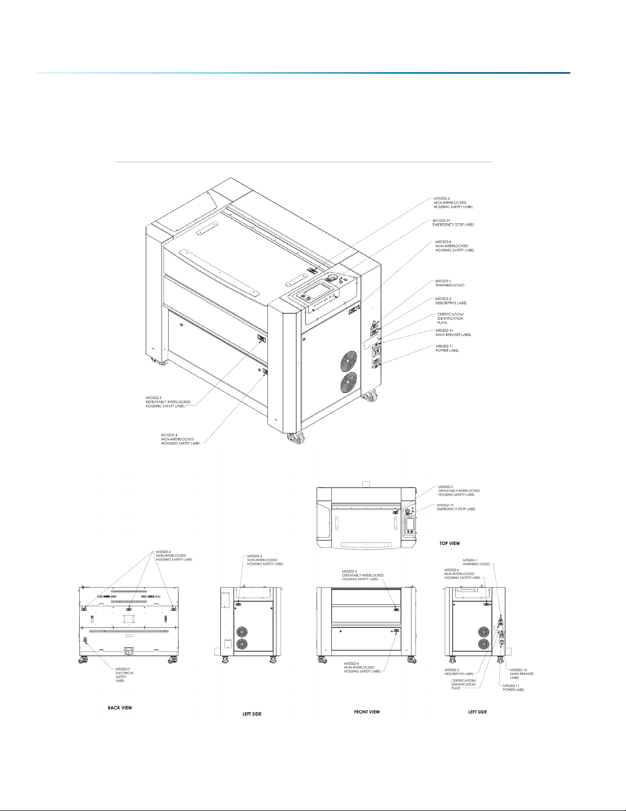
21 CFR 1040 and IEC 60825-1 require that certification, identification, and warning labels be placed on laser
products. Reproductions of labels on the Epilog Model 16000 Laser System follow, with their locations
specified:
1. Certification/Identification Plate: This engraved plate is located on the right side of the machine’s
cabinet.
2. Warning Logotype: This label is located on the right side of the machine’s cabinet, above the
Certification/Identification plate.
- 4 -
Page 9
SECTION 1: SAFETY
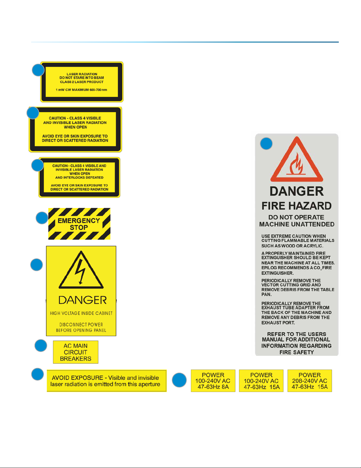
3. Descriptive Label: This label identifies the classification of the
3
4
5
Model 16000 in accordance with 21 CFR 1040.10 and IEC 60825-1. It is
located on the right side of the machine’s cabinet, below the Warning
Logotype.
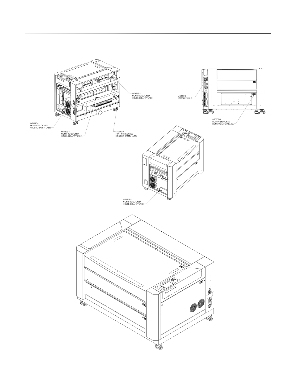
4. Non-interlocked Protective Housing Safety Labels: These labels
are located on, or adjacent to, removable access covers on the
machine’s cabinet as shown in the diagrams to follow. Where a label
is located on a removable cover, there is an additional label under
the cover so that it will be visible when the cover has been removed.
5. Defeatably-interlocked Protective
Housing Safety Labels: There is one
label on each of the machine’s cabinet
doors; one on the front door and one
on the top door.
6. Emergency Stop Label: This label is
located below the red Emergency Stop
switch on the top right side of the
machine.
11
7. Electrical Safety Label: This label is
6
7
8
9
located on the back of the machine in
the lower le hand corner.
8. Main Breaker Label: This label is
located on or above the power module
panel at the right side of the machine’s
cabinet.
9. Aperture Safety Label: This label is
located above the aperture, inside the
cabinet, where laser beams enter the
machine’s engraving area.
10. Power Labels: The appropriate label
for the machine is located on or below
the power module panel at the right
side of the machine’s cabinet.
11. Fire Warning Label: There are two
labels on top of the machine’s cabinet;
one to the le and one to the right of
the top cabinet door.
10
- 5 -
Page 10
SECTION 1: SAFETY
The following diagrams show the location of each specific label.
Fusion Pro 32:
- 6 -
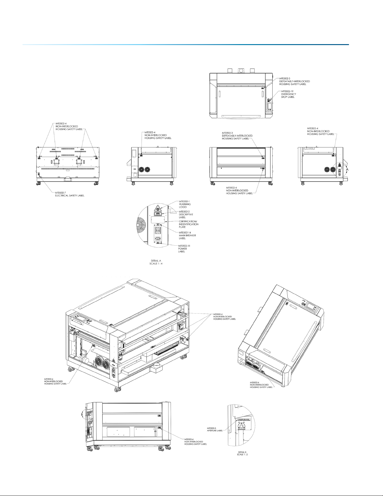
Page 11
SECTION 1: SAFETY
Fusion Pro 48:
- 7 -
Page 12
SECTION 1: SAFETY
- 8 -
Page 13

SECTION 1: SAFETY
FCC:
Supplier’s Declaration of Conformity
47 CFR Paragraph 2.1077 Compliance Information
Laser Materials Processing System Model 16000
Epilog Laser Corporation
16371 Table Mountain Parkway
Golden, CO 80403
Telephone: (303) 277-1188
This device complies with Part 15 of the FCC Rules. Operation is
subject to the following two conditions:
(1) This device may not cause harmful interference, and
(2) This device must accept any interference received, including
interference that may cause undesired operation..
NOTE: This equipment has been tested and found to comply with the
limits for a Class A digital device, pursuant to Part 15 of the FCC Rules.
These limits are designed to provide reasonable protection against
harmful interference when the equipment is operated in a commercial
environment. This equipment generates, uses, and can radiate radio
frequency energy and, if not installed and used in accordance with the
instruction manual, may cause harmful interference to radio
communications. Operation of this equpment in a residential area is
likely to cause harmful interference in which case the user will be
required to correct the interference at his own expense.
This product contains a Certified transmitter module (wireless network
interface), FCC ID: Z64-WL18DBMOD
- 9 -
Page 14
SECTION 1: SAFETY
Dos and Don’ts
Don’ts
Do Not Run the Laser Unvented: Never operate the machine without a properly operating vent to the
outside or to a filtration unit! Most material will only produce an irritating smoke when engraved.
Some materials, including but not limited to paint, varnish, composition board and plastics, produce
compounds that can be harmful if concentrated. A properly installed vent is the only way to ensure that
problems do not occur.
Do Not Engrave or Cut PVC: Never engrave or cut any material containing PVC or vinyl. When engraved,
a corrosive agent is produced that will destroy your machine. Your warranty will be void if your machine
is damaged by corrosion from engraving or cutting PVC or Vinyl.
Do Not Operate Machine While Unattended: Never operate your machine without someone watching
the system. There is a significant risk of fire if the machine is set improperly, or if the machine should
experience a mechanical or electrical failure while operating.
Do Not Vector Cut While Machine is Unattended: Never laser cut any material with the laser without
someone watching the system. Because vector cutting moves relatively slowly compared to raster
engraving, a tremendous amount of heat is applied to the material being cut. This buildup of heat can
cause significant fire risk and the machine should always be monitored. Additionally, the Air Assist should
always be turned on when vector cutting to reduce the risk of fire.
Do Not Operate The System While Doors are Open: Never operate with any of the covers or enclosures
removed, and never modify the enclosure. The laser beam is invisible and is very dangerous!
Dos
Clean the System: Please allow a few minutes a week for cleaning your machine. Just a small amount of
eort at the end of the week will pay o with years of trouble free operation of your machine.
- 10 -
Page 15

SECTION 2: GETTING STARTED
Setting up your Epilog Laser System is easy to do! If you’ve ever installed a paper printer, this is only
slightly more diicult. The following information will help you understand the entire system and how it
works.
Your Fusion Pro laser system consists of the following components:
1. Fusion Pro Laser System
2. Epilog Driver Disc
3. USB and Ethernet Cables
You will also need:
1. A computer or laptop.
2. An exhaust fan: The exhaust fan is mandatory and is used to remove smoke and debris from the
Fusion Pro work area. The exhaust air can be ported to the outside or into a filter box.
Follow these steps to setup your Fusion Pro Laser system:
1. Unpack the laser system.
2. Choose where to locate the system.
3. Connect the exhaust system to your laser.
4. Connect the electrical power.
5. Connect the laser to your computer through USB or Ethernet connection.
6. Sign up for driver updates and register your system at www.epiloglaser.com/register.
- 11 -
Page 16
SECTION 2: GETTING STARTED
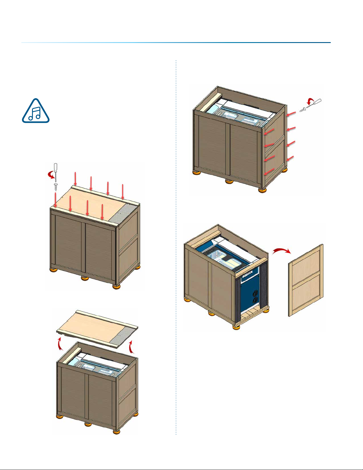
1. Unpacking the Laser System
Unpack the laser system from the crate
provided by Epilog. Please be sure to
hold on to all packing materials and
crating in case you need to move the
system in the future.
1. First, remove the screws securing the top lid
using a screwdriver.
3. Remove the screws securing the front panel.
4. Slide the front panel out of the box.
2. Remove the top lid and set it to the side.
- 12 -
Page 17
SECTION 2: GETTING STARTED
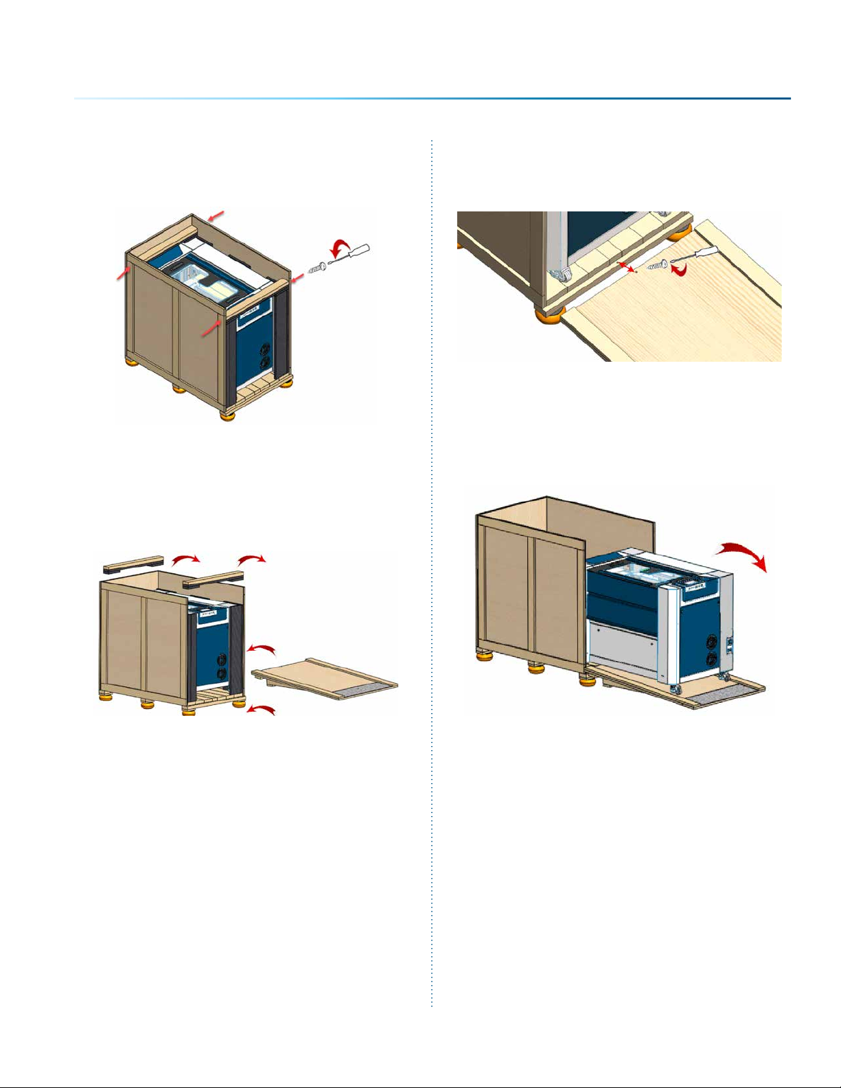
5. Remove the outer screws holding up the two
braces.
6. Remove the braces as well as any foam
pieces around the machine.
7. Using the top panel you removed at the
beginning, align its corners with the ledge on
the bottom of the box, making a ramp.
Secure the ramp with a screw.
8. Roll the machine down the ramp slowly and
carefully until it is out of the box and on level
ground.
- 13 -
Page 18
SECTION 2: GETTING STARTED
2. Choose Where to Locate the System
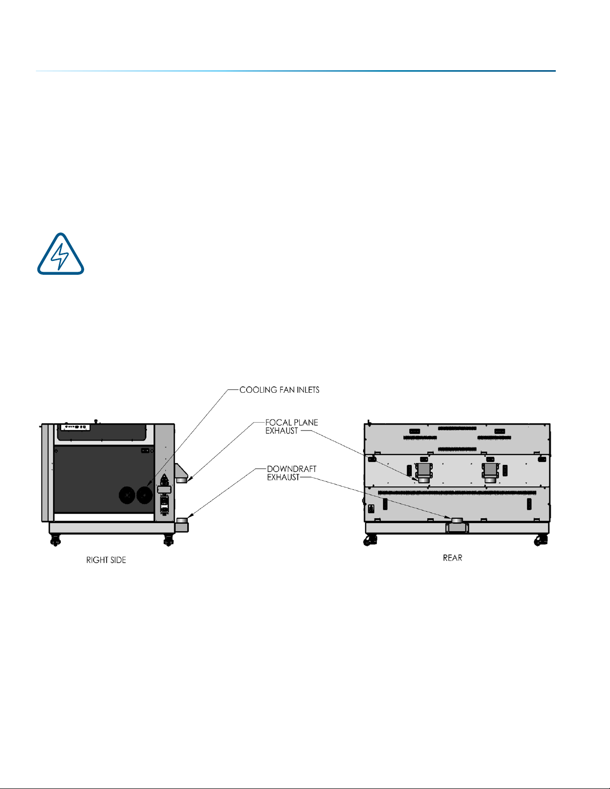
Cooling Requirements and Operating Temperatures
All Epilog Laser systems use air-cooled laser tubes. Laser technology is such that the laser tubes generate
a lot of excess heat and the tubes must be cooled for proper operation. There are cooling fans located
on both sides of the laser. The fans and vents should always be clear of restrictions and should never be
covered.
Warning: The cooling fans and vents are located on both sides of the Fusion Pro and should
never be covered or blocked in any way. Lasers that overheat will not operate properly and
may begin to produce erratic laser output or possibly complete failure.
Ambient air temperature where the laser system is operating should not exceed 90 degrees F (32 C).
Operating in an environment where the ambient air temperature is above 90 degrees F (32 C) will void the
Epilog warranty. For more information, see the “Warranty Statement for the Fusion Pro Laser” on page
127.
- 14 -
Page 19
SECTION 2: GETTING STARTED
3. Connecting the Exhaust
In this manual, the term “exhaust” refers to either an exhaust fan or a filter unit and the term “exhaust”
is used for simplicity. The important point is that it is mandatory that an exhaust unit or filter system is
incorporated as part of your laser system. Never operate your laser system without a properly functioning
exhaust. The exhaust removes the dust, debris and smell from the engraving cavity and exhausts it to
the outside of the building or to the filter unit. Prior to the installation of the laser system, you may need
a contractor to install the exhaust system. The blower should be mounted outside your building for noise
considerations. Ideally, the blower should not be more than twenty feet (6 meters) from the laser. You
should provide a metal duct (flexible aluminum or galvanized sheet metal) from the blower to the laser.
All Epilog model 16000 laser systems require an exhaust fan that is rated at a minimum of 800 CFM for
external exhaust.
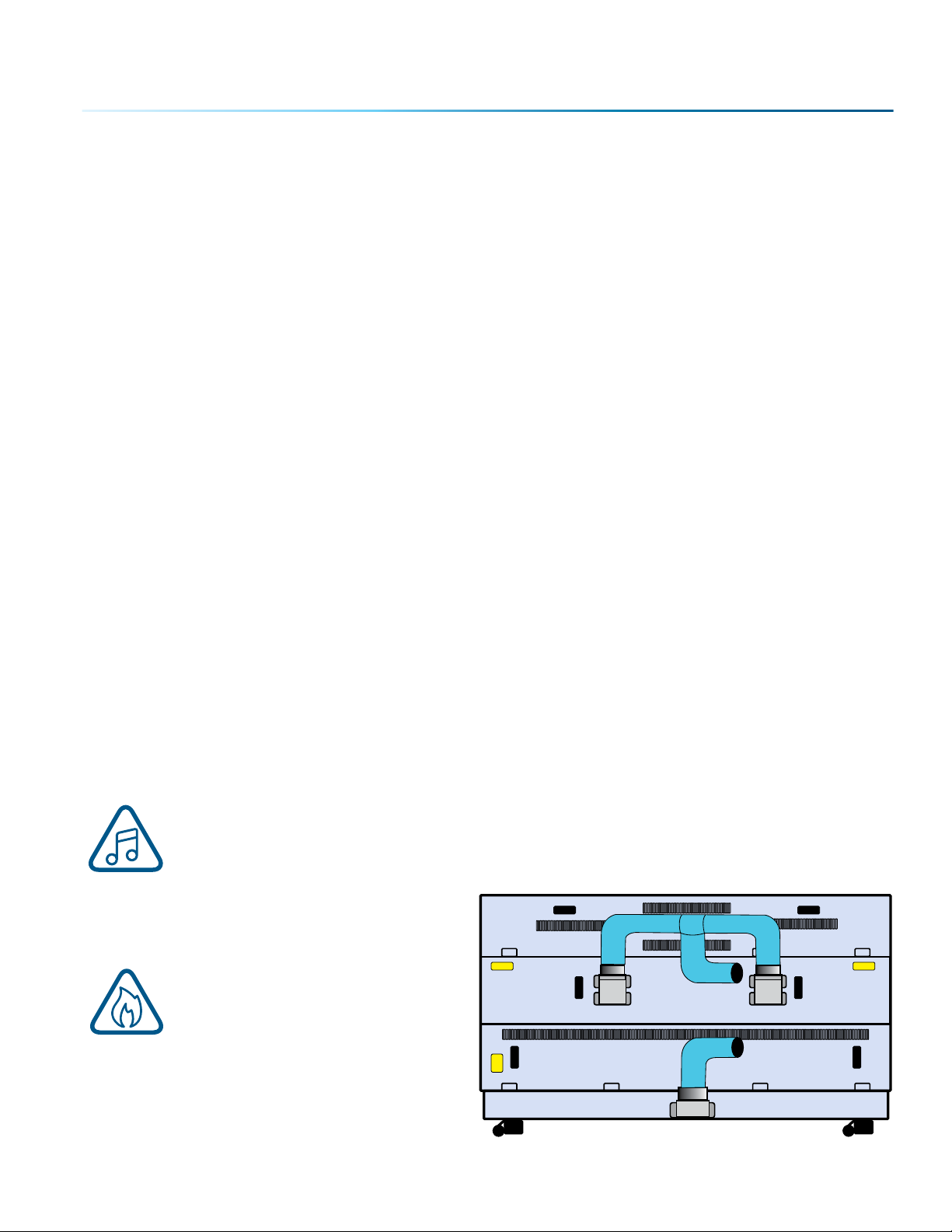
The exhaust requirements for the Fusion Pro 32 and 48 are the same:
• The Fusion Pro 32 model requires 400 CFM for the primary exhaust port (upper port) and 400 CFM for
the downdra exhaust port (lower port) totaling 800 CFM.
• The Fusion Pro 48 model also requires a total of 400 CFM for the two primary exhaust ports (200 CFM
per upper port) and 400 CFM for the downdra port (lower port) totaling 800 CFM.
Epilog provides recommended exhaust flow rates (CFM) only for direct ventilation exhaust systems
that are ported to the outside. Please note that this is also a recommendation and not a requirement,
because factors such as length and type of tubing from the Epilog laser to the exhaust fan and from the
exhaust fan to the outside of the building can produce significant losses on the true amount of air that
is drawn from the Epilog laser.
Exhaust flow rates (CFM) for filter systems are not specified in this document. However, exhaust flow rates
for filtration units will be lower than a direct ventilation exhaust systems because filters are designed to
be placed directly adjacent to the laser system and do not exhibit the air-flow losses that are typically
found with direct exhaust fans. Epilog has worked with most major filter manufacturers to recommend a
specific filter system for each model of Epilog laser. Please contact your Epilog distributor to match a
filter to the Epilog laser system you are using.
Note: Remember to put the blower switch for the laser system in an obvious and accessible
place so it can be routinely switched on prior to using the engraver. Please connect the
exhaust blower to the laser as shown below and on the following pages.
Remember, you may need a contractor to install
the exhaust. This must be done PRIOR to
installation of the laser system.
Warning: It’s important that either
rigid or flexible metal ducting be
used for all connections leading to
and from the laser system and the
exhaust fan. Vinyl, plastic, or any
type of “so” ducting is potentially flammable
and should not be used unless provided by the
filtration system manufacturer and made from
fire-proof materials.
- 15 -
Page 20
SECTION 2: GETTING STARTED
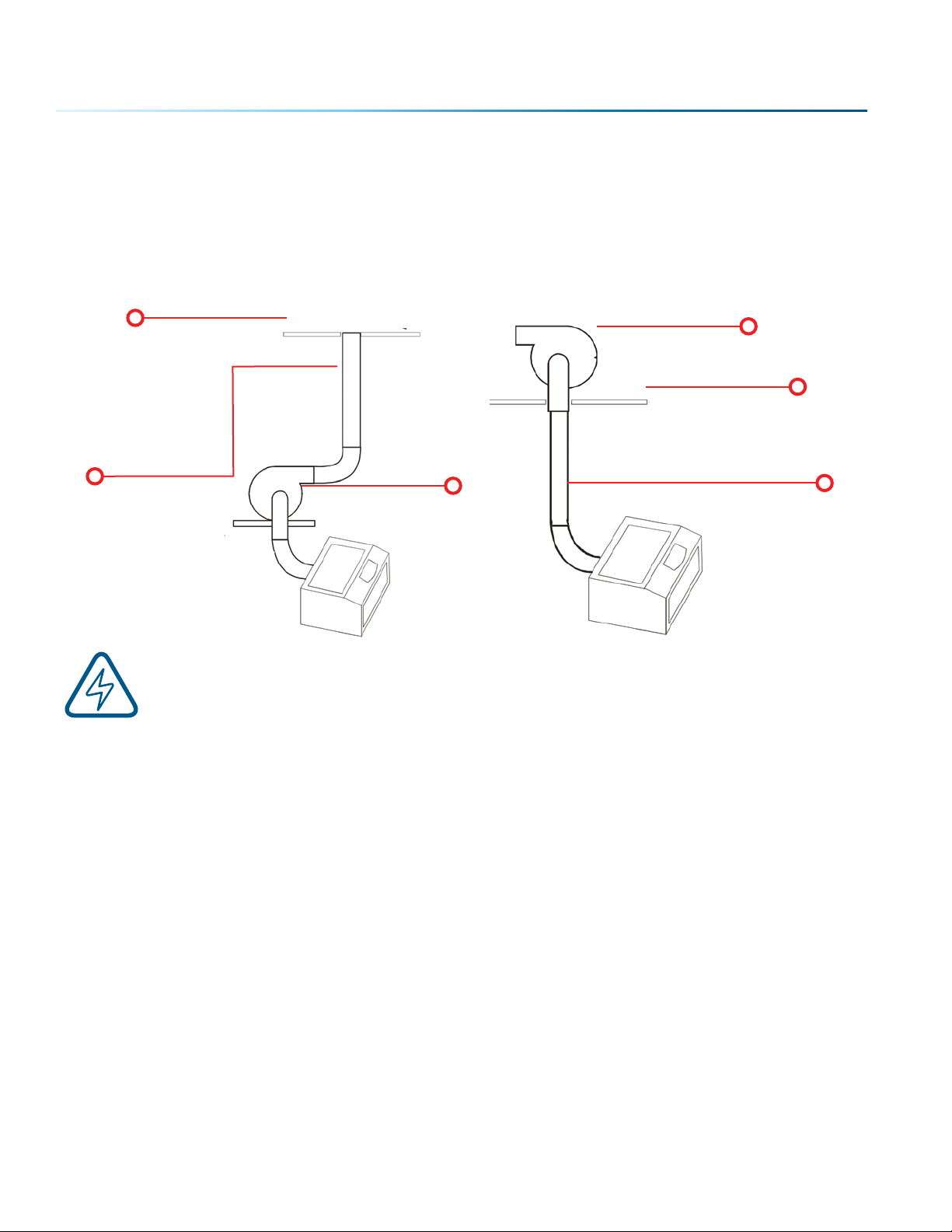
Epilog Exhaust/Filter Connections
There are two 4” (102 mm) ports attached to the back of the Fusion Pro 32 laser system, and three 4” (102
mm) ports attached to the back of the Fusion Pro 48 laser system. Attach your ducting to the machine as
shown in the diagram.
Roof or Exterior Wall
4” (102 mm) flexible
aluminum duct or
rigid galvanized
sheet metal (do
not use vinyl,
plastic or “so”
flexible duct).
Check your exhaust system for leaks. Most small leaks can be remedied with duct tape.
DO NOT OPERATE your laser with inadequate or leaking exhaust.
The drawings above show the typical exhaust setup. The le drawing shows the exhaust near the
machine and the right drawing shows the exhaust fan on the roof. Where the exhaust fan is placed is a
choice of personal preference. Some users like the exhaust fan outside because of noise considerations.
Exhaust Blower
Exhaust Blower
Roof or Exterior Wall
4” (102 mm) flexible aluminum
duct or rigid galvanized sheet
metal (do not use vinyl, plastic
or “so” flexible duct).
- 16 -
Page 21
SECTION 2: GETTING STARTED
4. Connecting Electrical Power
Epilog supplies the appropriate power cord
for the system you ordered. The power cord
is found in the accessory package with your
machine. The power cord for the laser plugs
into the power receptacle located on the le
side of the machine in the rear corner. It is
recommended that a dedicated 15 amp circuit
be used if available, but it is not required.
The Fusion Pro 48 laser system requires
208/220/240 volt electrical power. This system
will not operate on 120 volt power. The Fusion
Pro 48 power cord comes with a male plug
type NEMA L6-15R (which is a Hubble HBL4570C
equivalent).
We recommend using 208/220/240 volt electrical power on all systems to achieve maximum peormance.
For more information, see “Fusion Pro Electrical Specifications” on page 3.
Electrical Connection
220 V-50/60 Hz
5. Connect the Laser to Your Computer
You are now ready to connect your computer to the laser. The following connections can be used:
1. USB only connection: You can use the USB port for connecting to the Epilog Job Manager. Multiple
laser systems cannot be operated from a single computer through the USB connections. If you are
using the USB connection, you will need one computer for each laser system.
2. Ethernet only connection: With an Ethernet connection you can print from the Laser Dashboard
and use the Epilog Job Manager.
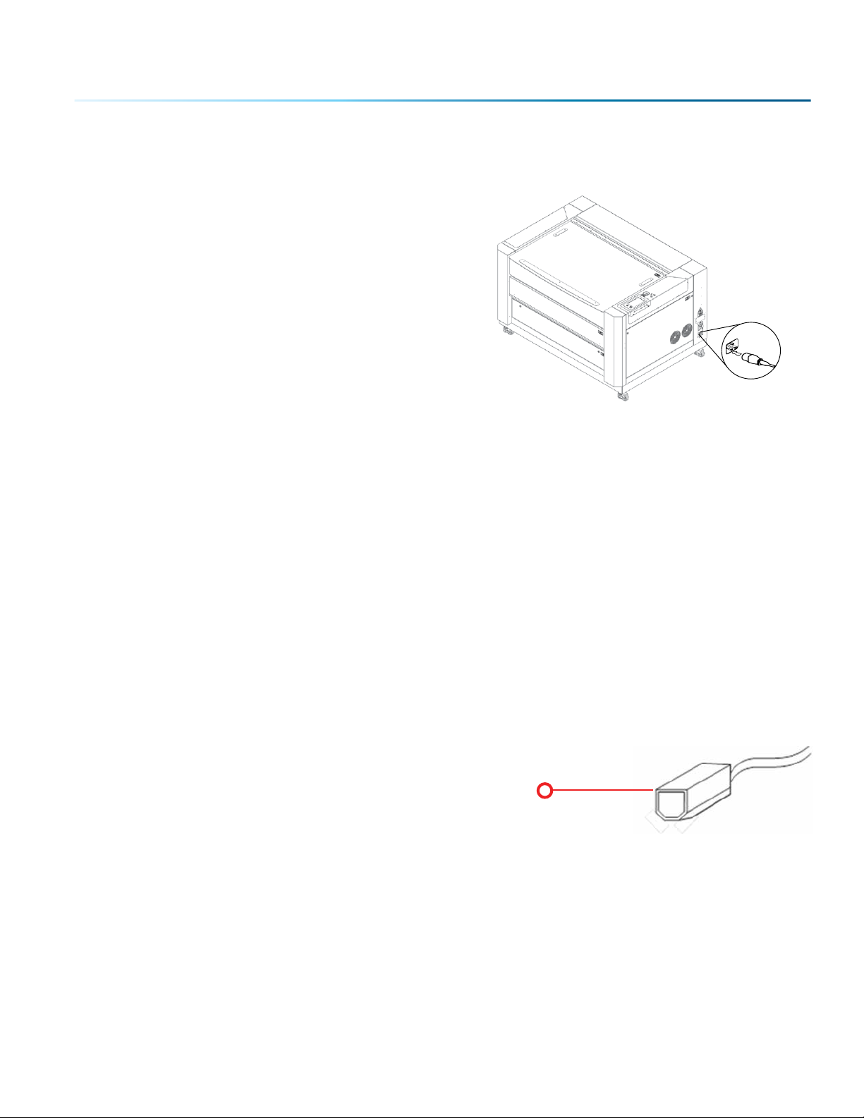
USB Connection
A USB cable is included in the accessory kit. The USB port is
located on the right hand side of the machine. USB cables have
dierent connectors on each end. The USB connection will
behave similarly to an Ethernet cable when communicating
with the laser. Both the computer and machine should
recognize the USB without any need to reboot.
Connect to the laser
- 17 -
Page 22
SECTION 2: GETTING STARTED
Ethernet Connection
The Ethernet Port is a standard 10BaseT connection. Your Epilog Laser has all of the versatility of a
network capable peripheral. As such, there are many dierent ways that the laser can be connected
to a computer or a network. A direct connection using an Ethernet cable is the only method that will be
described in this manual. Connect the Ethernet cable (included in the accessories kit) to the Ethernet
port, located on the right hand side of the machine. Plug the cable into the Ethernet port on the laser,
then plug the other end into the Ethernet port on your computer.
The Epilog Dashboard is the print driver that allows your computer to talk to your Epilog Laser system
when either the USB or Ethernet cables are connected. The driver is included in the accessories kit on a
CD-ROM or on our website at www.epiloglaser.com. To see detailed instructions on installing the print
driver, see “SECTION 3: SOFTWARE INSTALLATION” on page 21.
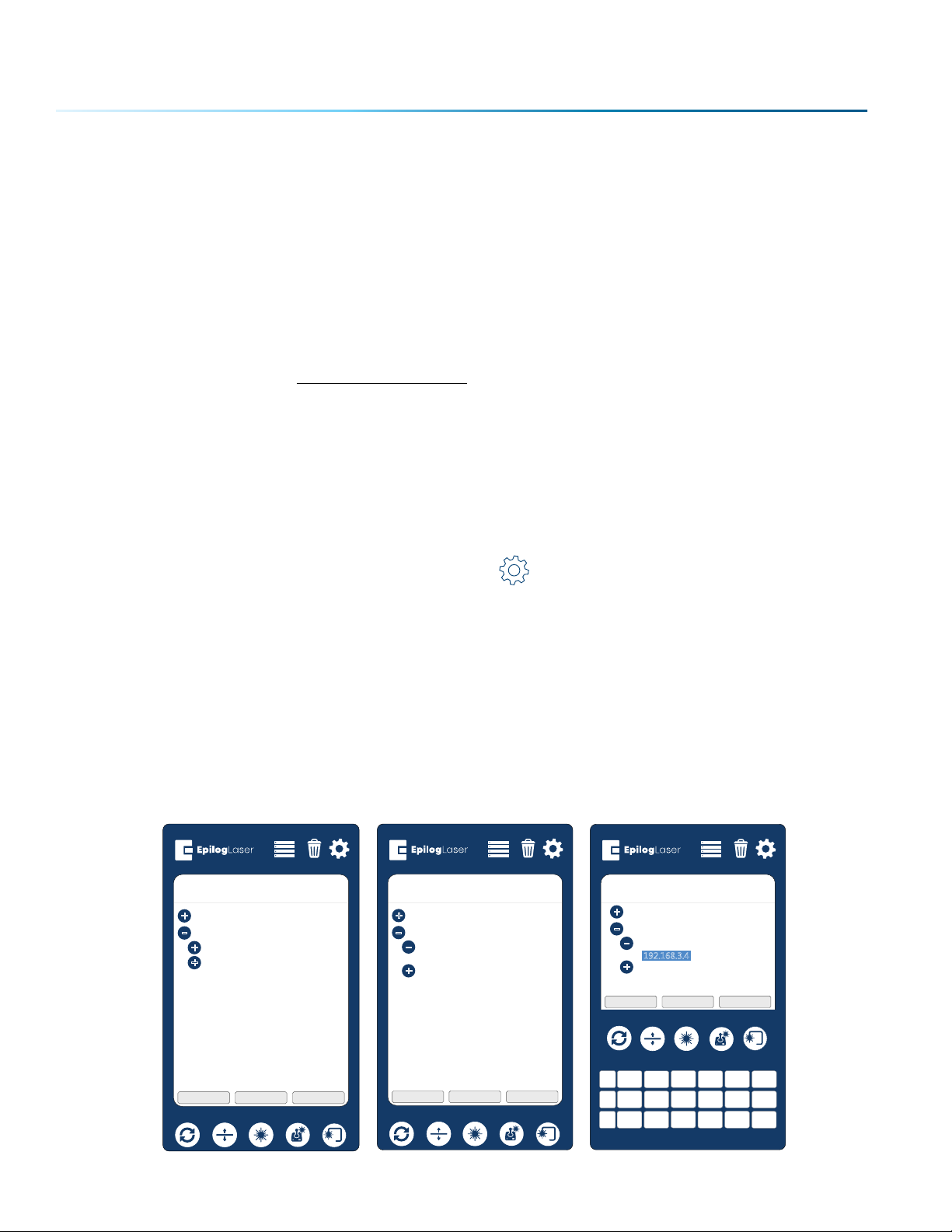
6. Set the Fusion Pro’s IP Address
Ethernet Cable Setup
1. Once your machine is booted up, select the Settings button in the upper right corner of the
touchpad.
2. Select Network in the settings list.
3. Under Network you will see “IP Address” and “Netmask”, press “IP Address” and then press the
numbers that appear next to them. A keyboard should show up at the bottom of the screen.
4. Press the “123” Button in the bottom le corner of the keyboard to access the numerical keypad.
5. Type in whichever IP Address you prefer to use. Most Epilog users will use the IP Address of 192.168.3.4
which is what we use in this manual.
6. Press the Close key to close the keyboard, then press the Job Menu Button to return to the main
screen and your settings should be saved.
+
System
Network
-
+
+
Settings
IP
Address
Netmask
+
System
Network
-
-
+
Settings
IP
Address
192.168.3.4
Netmask
Idle
Settings
+
System
Network
-
Address
IP
-
192.168.3.4
Netmask
+
Park Axis Home Axis Home Table
Park Axis Home Axis Home Table
Idle
Park Axis Home Axis Home Table
Idle
- 18 -
+
7 8 9 ,
-
4 5 6
1
SP 2 3 0
.
“
< >
ABC Del
Enter Close
Page 23
SECTION 2: GETTING STARTED
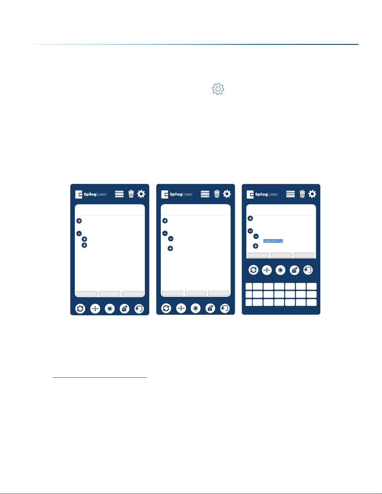
USB Cable Setup
1. Once your machine is booted up, select the Settings button in the upper right corner of the
touchpad.
2. Select USB in the settings list.
3. Under USB you will see “IP Address” and “Netmask”, press “IP Address” and then press the numbers
that appear next to them. A keyboard should show up at the bottom of the screen.
4. Press the “123” Button in the bottom le corner of the keyboard to access the numerical keypad.
5. Type in whichever IP Address you prefer to use. In this case we used 169.254.7.2
6. Press the Close key to close the keyboard, then press the Job Menu Button to return to the main
screen and your settings should be saved.
Settings
+
System
Network
USB
-
IP
Address
+
Netmask
+
Park Axis Home Axis Home Table
Idle
Settings
+
System
Network
USB
-
IP
Address
-
169.254.7.2
Netmask
+
Park Axis Home Axis Home Table
Idle
Idle
+
-
SP 2 3 0
Settings
+
System
Network
USB
-
IP
Address
-
169.254.7.2
Netmask
+
Park Axis Home Axis Home Table
7 8 9 ,
4 5 6
1
.
ABC Del
Enter Close
“
< >
7. Sign Up for Driver Updates and Register Your
System
Go to www.epiloglaser.com/register and register your system. You can also sign up for our monthly
e-newsletter, quarterly customer printed newsletter, and sign up for driver update notifications.
- 19 -
Page 24

Page 25
SECTION 3: SOFTWARE INSTALLATION
Epilog Job Manager Instructions
The Epilog Job Manager is a poweul new tool that will quickly become one of your favorite features
on your laser system. From one piece of soware, you can access any job you have sent to the laser,
view the settings you used on any past job, re-run projects, access your material database, and much
more. It’s a great addition to the Epilog Laser product features, and we look forward to seeing how our
customers use this soware!
• Windows 7/8/10 is required to use the Epilog Job Manager.
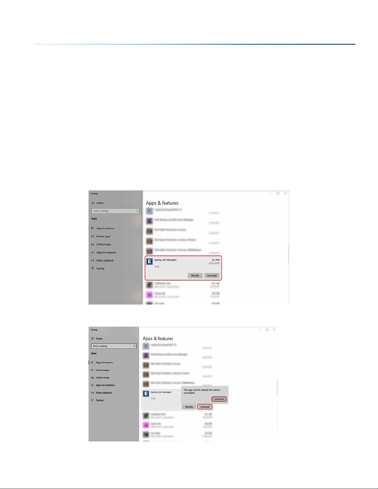
Uninstalling the Previous Job Manager
If you have installed a previous version of the Job Manager on your computer, you must uninstall it first
before you continue.
1. Go to Control Panel > Programs and Features and click on Epilog Job Manager
2. Click “Uninstall” and confirm if asked again.
- 21 -
Page 26
SECTION 3: SOFTWARE INSTALLATION
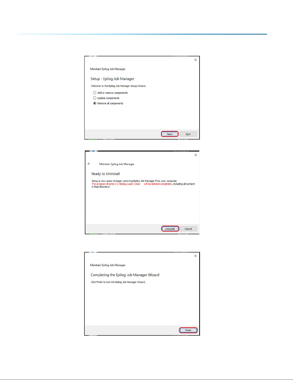
3. Select “Remove all components” and then click “Next”.
4. Click “Uninstall”.
5. Click Finish to complete the uninstallation of the previous Job Manager.
- 22 -
Page 27
SECTION 3: SOFTWARE INSTALLATION
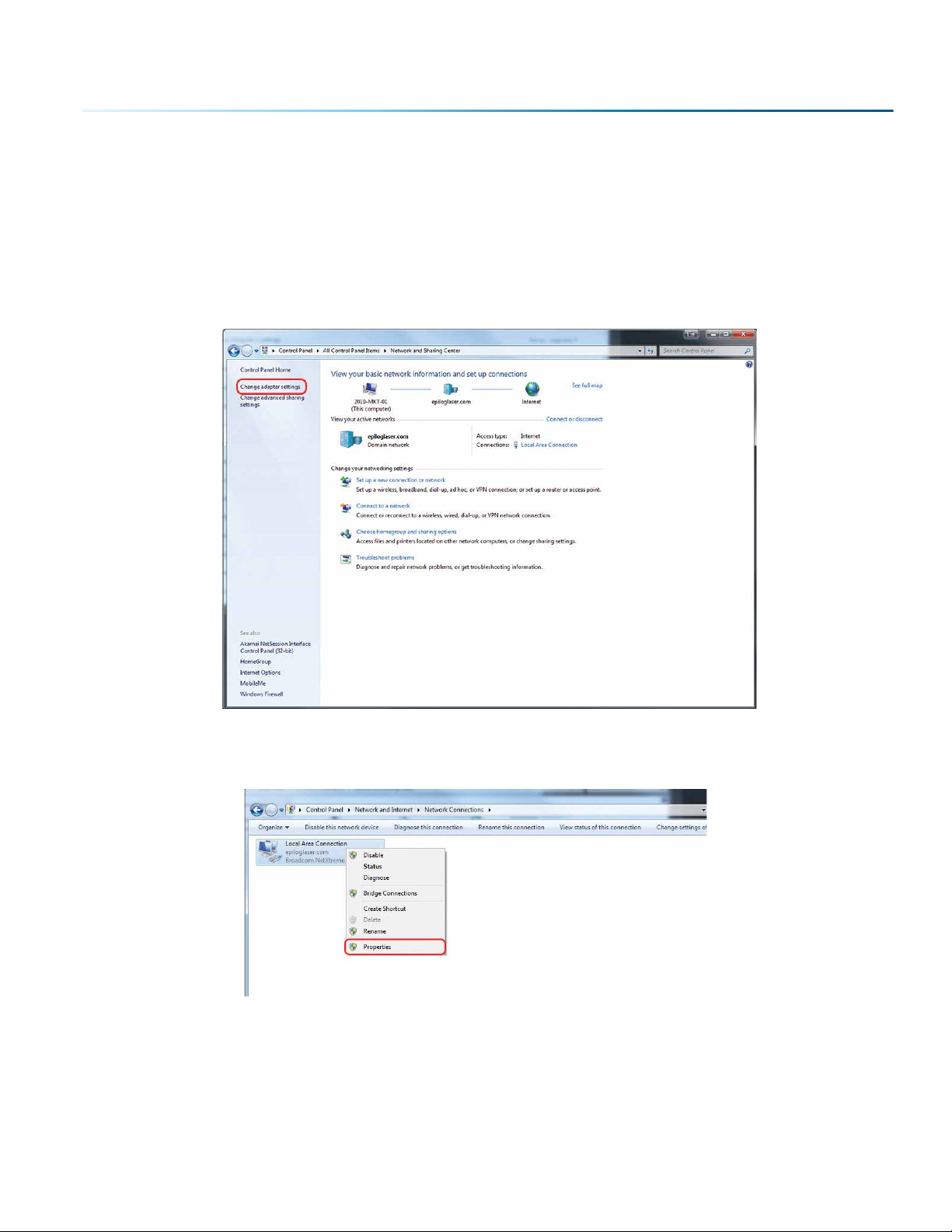
Windows 7: Ethernet Installation
Set Up TCP/IP Address in the Computer
Go to your Network and Sharing Center in your computer’s Control Panel.
1. Click Change Adapter Settings.
2. Right click Local Area Connection, then click Properties.
- 23 -
Page 28
SECTION 3: SOFTWARE INSTALLATION
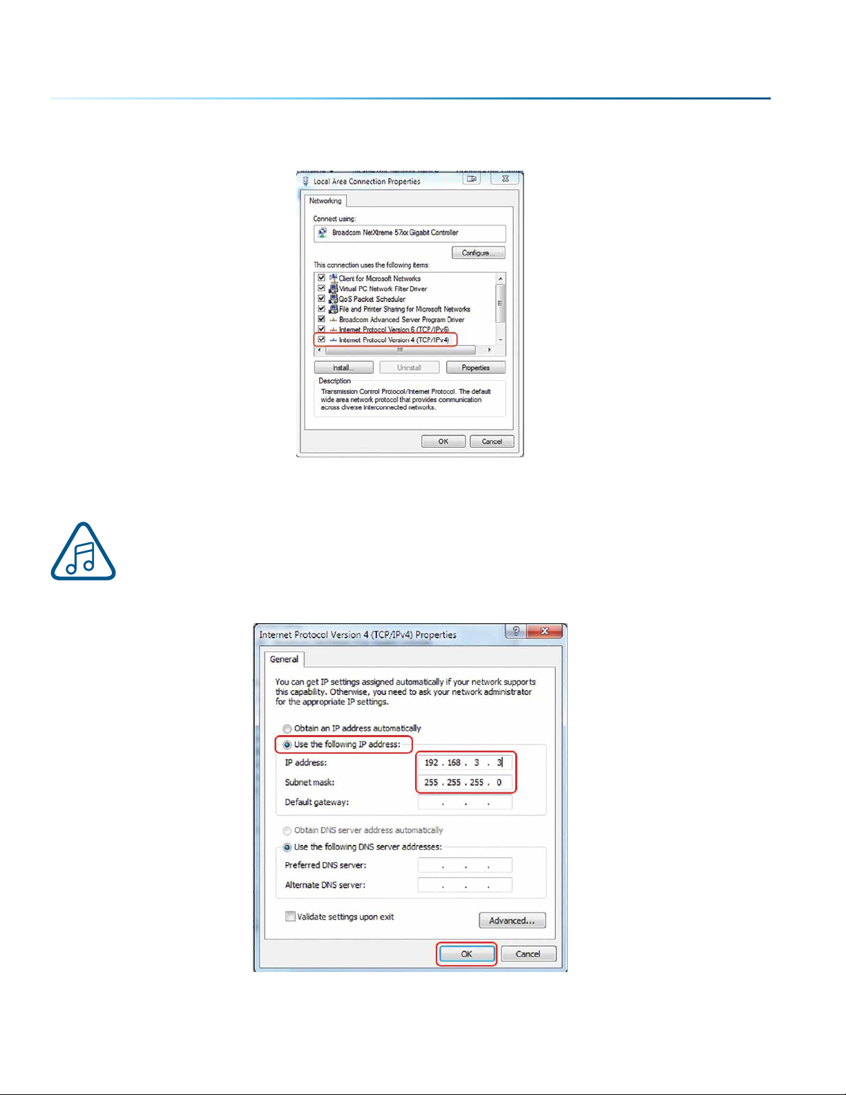
3. Select Internet Protocol Version 4 (TCP/IP). Make sure you do not select Version 6.
4. Select Use the following IP Address. Type in the following IP Address: 192.168.3.3.
This number is not an error; the last digit of the IP address in this window must be dierent
than the IP address you set in the laser.
Type in a Subnet Mask of 255.255.255.0, then click OK.
- 24 -
Page 29
SECTION 3: SOFTWARE INSTALLATION
How to Install the Epilog Job Manager
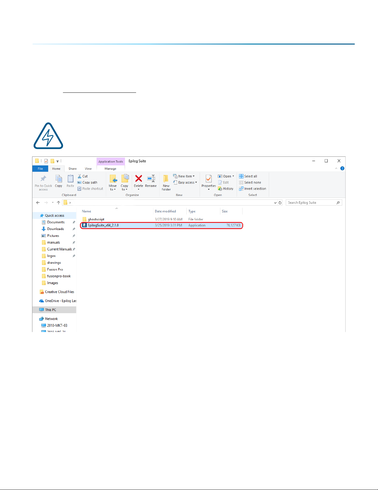
1. Go to epiloglaser.com/drivers and select the Epilog Fusion Pro. Then click on the Epilog Soware
Suite to download the installation file.
2. The installation file will download as a .zip folder that will need to be extracted. Right click the
folder and click “Extract All”. Once finished, double click on the EpilogSuite file.
Note: Make sure that the “Ghostscript” folder included in the download is always in the same
location as your Epilog Suite installation file, or the installation will not be able to complete.
- 25 -
Page 30
SECTION 3: SOFTWARE INSTALLATION
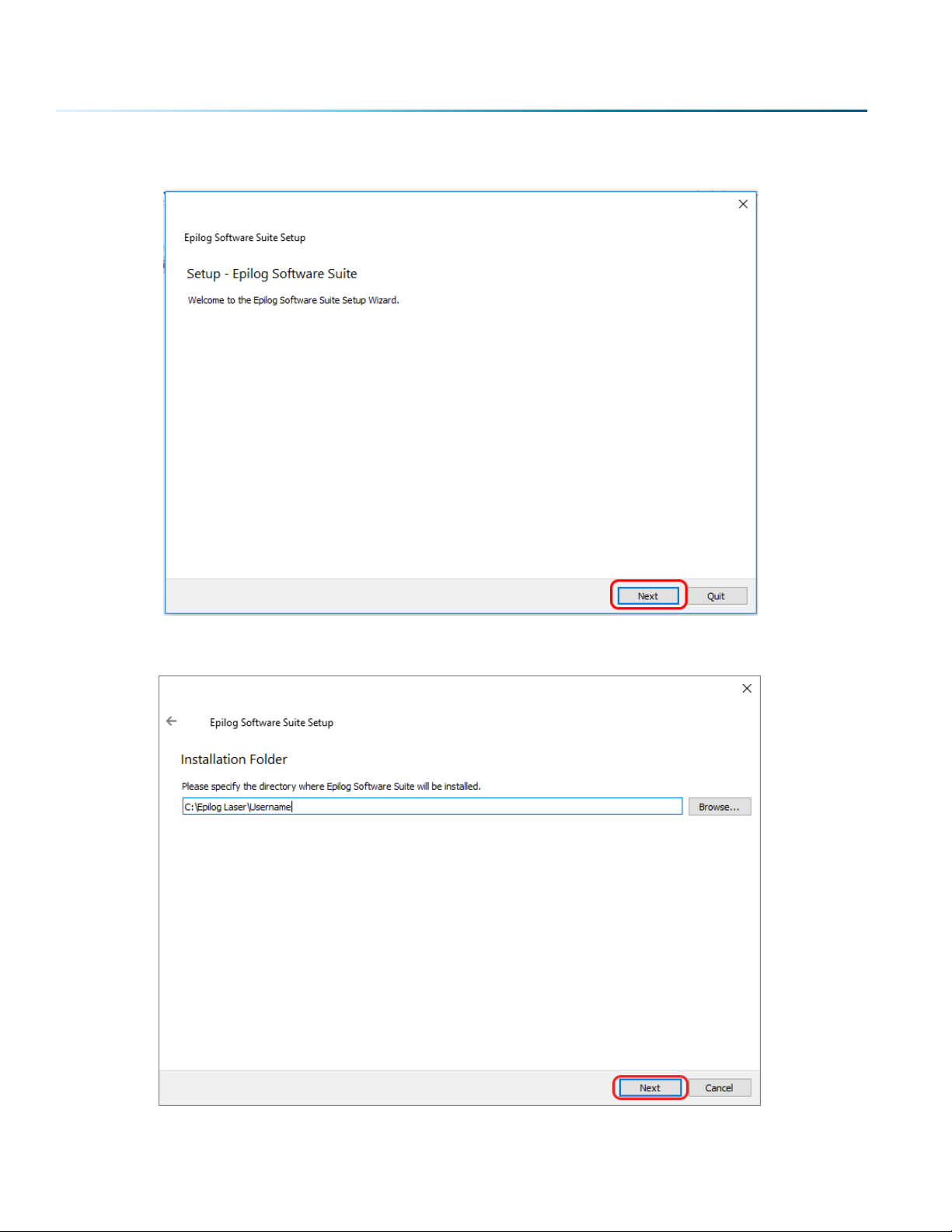
3. A welcome screen appears, click Next.
4. Select a directory location for the installation file and click Next.
- 26 -
Page 31

SECTION 3: SOFTWARE INSTALLATION
5. Read and accept the license agreements and click Next.
6. Click Next to use the default start menu, or choose a start menu name of your choice.
- 27 -
Page 32

SECTION 3: SOFTWARE INSTALLATION
7. Click Install to begin the installation.
8. The Epilog Soware Suite will begin installing, during the installation a dialog box will pop up to
also install the AGPL Ghostscript Package, click Next.
- 28 -
Page 33

SECTION 3: SOFTWARE INSTALLATION
9. Read and accept the AGPL Ghostscript License Agreement, then click Next.
10. Click Finish to complete the AGPL Ghostscript installation and resume the Epilog Soware Suite
installation.
- 29 -
Page 34

SECTION 3: SOFTWARE INSTALLATION
11. Select whether or not you want to run the program now. Click Finish to complete the installation.
12. An icon for the Job Manager will be automatically added to your Desktop. You are now ready to
use the Job Manager.
- 30 -
Page 35

SECTION 3: SOFTWARE INSTALLATION
Troubleshooting the Job Manager
If you were unable to install the Job Manager, it’s possible that your Anti-Virus soware is blocking
installation.
To disable Symantec Anti-Virus soware, choose Options. Other anti-virus packages should have
something similar to Symantec.
Disable all Virus and Spyware Protection Features. Aer the Job Manager has been installed go back
into your Anti-Virus soware and re-enable the setting that was disabled.
- 31 -
Page 36

SECTION 3: SOFTWARE INSTALLATION
Important Job Manager Notes
• Warning: Before activating your laser, install the newest version of the driver to properly
associate the correct machine with the Job Manager.
• We suggest a minimum of 1 GB of free RAM space when managing very large raster and vector jobs.
- 32 -
Page 37
SECTION 4: THE JOB MANAGER
Using the Epilog Job Manager
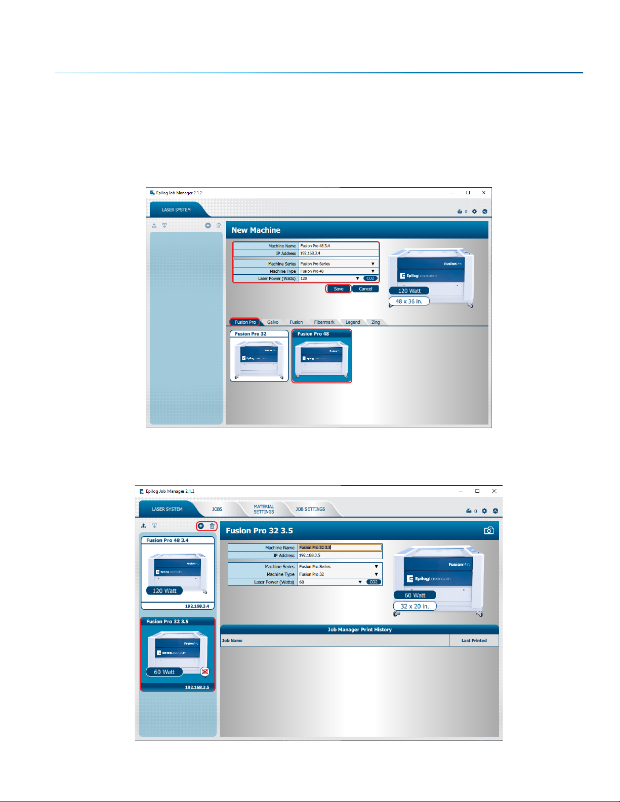
1. The first time you open the Job Manager you’ll see a tab for each of the machine models. Begin by
selecting the correct model, naming your machine, setting the IP Address, and selecting the correct
laser wattage, then click Save.
2. Your new laser has been activated in the Job Manager and now appears in the le panel. It is now
ready to accept jobs from the print driver. Use the Add or Delete buttons to add or remove
additional machines. Below you can see we have installed an additional Fusion Pro 32 laser system.
- 33 -
Page 38

SECTION 4: THE JOB MANAGER
Printing to the Epilog Job Manager
Create a file in your graphic soware and select Print. When the print dialog opens up, make sure you
select Epilog Engraver as your printer and set the Page to Match Orientation and Size. Once your desired
settings are selected, click Print again.
Organizing Your Print Jobs
Click the Jobs tab. All print jobs will be displayed in the Uncategorized folder. Click on your job to highlight
it. You can now Print, Edit, Preview or Delete this job using the available icons.
- 34 -
Page 39

SECTION 4: THE JOB MANAGER
Create and Delete Job Folders
Click the Add Job Folders icon to add folders. You can add as many folders as you’d like.
Type in the folder name and click the check mark to create your new folder.
- 35 -
Page 40

SECTION 4: THE JOB MANAGER
Move an Uncategorized File to a Folder
When you highlight a folder you will see From Uncategorized on the right side of the folder. Click From
Uncategorized to move a job from the Uncategorized folder to this subfolder. Select the job you want to
move and click OK.
Create Subfolders
First, highlight the folder in the le panel where you want to add a subfolder. Below we have highlighted
the Betty’s Electronics folder. Click the Add Subfolder icon. Type the subfolder name in the Add Subfolder
field, then click the check mark to create the subfolder.
- 36 -
Page 41

SECTION 4: THE JOB MANAGER
Move a Job Between Folders
You can also move any job to another folder or subfolder by clicking and dragging it up or down between
folders. An arrow will indicate where you are placing the job. Once you see the arrow selecting the correct
folder, let go of the job file to place it in that folder.
Switch Machine Selection
By clicking on the machine photo in the upper le corner, you can quickly change which machine model
you want to have active.
- 37 -
Page 42

SECTION 4: THE JOB MANAGER
Previewing Your Job
To view a preview of the job, double click on one in the Jobs Tab. A Preview Tab will open and you can
preview the combined raster vector job, just the raster components, or just the vector components. We
have selected vector to show only the vector components of this job. The preview mode is very useful in
identifying unwanted vector components in a job. For more information, see “Presetting Your Cut Lines”
on page 52.
Searching for a Job
The Job Manager has a poweul search function. Type in part of a file name and press enter to find all
files related to that name. You can organize files by Standard, Created, Last Printed, or Alphabetically to
find a specific file.
- 38 -
Page 43

SECTION 4: THE JOB MANAGER
Notice that the jobs are displayed dierently if you change the search category to Alphabetical. Your
jobs are now displayed in alphabetical order. Once the search is finished, most users revert back to the
default selection of Standard.
Finding Job History
You can find the Job Manager Print History under the Laser System tab to see a full print history of a
machine, including settings you used in each print. Clicking on each job will expand it and reveal its
settings. Clicking on each machine’s icon will only reveal the print history on the selected machine.
Under the Jobs tab you can modify, print or save jobs from this window using the listed settings or with
new settings. The new settings will be saved as the next print job complete with time stamp and date.
You’ll see which machine it was printed to, when it was first printed (Initial Print), all subsequent prints,
and all laser parameters used. To access this, double-click on the job, then select History. To view the
laser parameters of this job, click on the print version. In this example we have clicked on the Initial Print.
- 39 -
Page 44

SECTION 4: THE JOB MANAGER
Vector Sorting
You can determine the cutting order of vector lines directly from the Epilog Job Manager.
You can choose from three dierent vector sorting options:
1. None: Vector line cutting order is determined by the order they were created.
2. Inside/Out: All internal vector paths in the file will be process prior to the external vector paths. For
example, if cutting the letter O, the inner oval will be cut before the outer oval.
3. Optimized: The laser will process the vector lines looking for the next closest node for quicker
vectoring.
- 40 -
Page 45

SECTION 4: THE JOB MANAGER
Material Settings Tab
The Material Settings Tab allows you to save and import settings for individual processes. If you frequently
use the same settings for engraving or cutting, this feature allows you to import those settings into a
single process quickly.
Saving Material Settings
1. To save a process setting, first you need to create a folder in the Job Manager under the Material
Settings Tab by clicking the “Add Subfolder” button.
2. Name the folder and click the check mark to save it.
- 41 -
Page 46

SECTION 4: THE JOB MANAGER
3. Now go to the Epilog Dashboard and set up the file to your preferred settings. Click on the process
that has settings you want to save. In this example we have clicked on CMYK Blue. The Process box
should open, then click the “Export Settings to Material” button.
4. A box will appear asking you to name the Material Setting and select a folder to save it in. Fill out
this information and then click “Save”.
- 42 -
Page 47

SECTION 4: THE JOB MANAGER
Importing Material Settings
1. To import previously saved settings to a new job, click on the process you want to apply the
settings to. Then click the “Import Material Settings” button.
2. A box will appear asking you to select the settings you want to load into this process. Select your
settings and click “Import”.
3. The material settings should load on to that process and be ready to print to the laser.
- 43 -
Page 48

SECTION 4: THE JOB MANAGER
Job Settings Tab
The Job Settings Tab allows you to store all the information that is in a job, except for the artwork, as a file
you may import into future jobs. If you have a project you run frequently that requires the same settings
every time, this feature allows you to import those settings quickly.
Saving a Job’s Settings
1. To save a job’s settings, first open the job in the Epilog Dashboard and set up the file as you
normally would to print. Once your settings are ready to save, click the Export Job Settings button
at the bottom of the screen.
2. A box will appear asking you to name the Job Settings file and select a folder to save it in. Fill out
this information and then click “Save”.
- 44 -
Page 49

SECTION 4: THE JOB MANAGER
Importing Job Settings
1. To import previously saved settings to a new job, click the Import Job Settings button at the bottom
of the screen.
2. A box will appear asking you to select the settings you want to load into this job. Select your
settings and click “Import”.
3. The job settings should load into the file, ready for printing to the laser.
Note: You may also create Job and Material settings from scratch in their respective Job
Manager tabs.
- 45 -
Page 50

SECTION 4: THE JOB MANAGER
Changing Program Settings
You can access the Program Settings by clicking on the gear at the top right of the page.
On this screen you can set several dierent system settings, including:
Display Tab:
• Language: Choose from several languages.
• Default Length Units: Choose from inches, centimeters, or millimeters.
Dashboard Tab:
• New Job Settings: Uses the Epilog Default, Previous Settings, Split by Color, Split by Hairlines, or Split
by Color and Hairlines. For more information see “Dividing Your Job Into Processes” on page 53.
• Open Job Manager Automatically: When “Send to JM” is clicked, and this option is On, the Job
Manager will automatically be opened.
• Discard Aer Printing: When “Print” is clicked, and this option is On, the job will be discarded.
Alerts Tab:
Choose when the program asks for confirmation when you delete machines, folders, subfolders, or jobs
and materials.
Database Tab:
• Backup Database: Save a backup of all files, material settings, etc.
• Restore Database: Reload settings from a previous backup.
• Clear Entire Database: Delete all settings, machines and jobs from the database.
• Clear All Jobs: Delete all jobs in the database.
• Clear Uncategorized: Clear out all uncategorized jobs in the database.
• Clear Dashboard Jobs: Delete all queued jobs in the database.
We will be adding new features to the soware oen, so sign up for the Driver Update
Notification list at www.epiloglaser.com/tech-support/epilog-drivers.htm.
- 46 -
Page 51

SECTION 5: THE LASER DASHBOARD
The Epilog Dashboard is your portal between your graphic file and the laser. Install your Dashboard at
epiloglaser.com/drivers. There are four main areas we’ll cover to get you started:
1. Sending Your First Project
2. Presetting Your Cut Lines
3. Placing Artwork
4. Dividing Your Job into Processes
If you have worked with Epilog’s previous print driver, you’ll see some new ways that the
Dashboard lets you interact with your file. It may seem dierent at first, but you’ll quickly find
that you can still use your traditional methods of printing to the laser, or use several new ones
that make file setup quicker and easier!
- 47 -
Page 52

SECTION 5: THE LASER DASHBOARD
Setting Up CorelDRAW for the Laser
If you are using CorelDRAW, first make this quick, one time change to the settings.
1. Go to Tools > Options > Global > Printing > Driver Compatibility.
2. Select Epilog Engraver from the drop-down list.
3. Select “Printer can match document page sizes”, and click OK. You’re ready to go!
- 48 -
Page 53

SECTION 5: THE LASER DASHBOARD
Sending Your First Project
1. When you have your file designed, print it to the laser. Choose the Epilog Engraver as your printer
and set the Page to Match Orientation and Size.
2. Click on the Color tab and select Output colors as RGB. Then click Print.
- 49 -
Page 54

SECTION 5: THE LASER DASHBOARD
3. Your file will open in the Laser Dashboard. Select “To Fit” to zoom in on your object.
4. On the right side of the screen you can see two processes in the process list: Engrave and Vector.
These layers automatically separated because we set the line width of cut lines to .003”
(0.077 mm) or thinner). You can set the Dashboard to automatically separate vector lines
by line thickness, color, or no action. For more information, see “Presetting Your Cut Lines”
on page 52.
- 50 -
Page 55

SECTION 5: THE LASER DASHBOARD
5. With the Engrave process selected, we can now adjust the settings for this process.
• Process Name: Click on the process name (“Selection” in this
example) to rename the process.
• Run Time: Each process will show an estimated run time, which
depends on the size of the artwork, the Speed settings and the
Resolution settings.
• Split By: Select either “Color” to move every color in the graphic
to separate processes (useful for color mapping), or “Hairlines”
to manually move .003” (0.077 mm) or thinner vector lines to a
separate process.
• Merge With: Merge the current process with another process
layer. For more details, see “Merging Processes” on page 57.
• Process Type: Choose if you want the process to be “O”
(ignored by the laser), “Engrave”, or “Vector”.
Setting the process to Engrave will engrave all graphics and
lines, regardless of line width.
Setting the process to Vector will ignore any raster graphics and
only cut all vector lines in the process, regardless of line width.
• Resolution can be set anywhere between 75-1200 DPI. For more information about resolution, see
“Resolution” on page 81.
• Set your Speed and Power. Frequency will only be active when the process type is set to Vector.
For more information, see “Frequency” on page 65.
• Dithering / Vector Sort: The dithering drop-down will appear for Engrave processes, and Vector
Sort for Vector processes.
For more information on Dithering settings, see “Image Dithering” on page 87.
For more information on Vector Sorting, see “Vector Sorting” on page 40.
• Cycles: How many times to repeat this process.
• Laser: This will only appear if you are working with a Dual Source machine. Choose between the
CO2 and Fiber laser for each process.
• Thickness: This feature will be available soon.
• Oset: Only activated if Auto Focus is turned on. Set the oset you would like. For more
information, see “Oset” on page 65.
• Registration: Feature coming soon.
• Direction: Choose whether you want the engraving to start at the bottom of your piece or the
top. For more information, see “Engrave Direction” on page 64.
- 51 -
Page 56

SECTION 5: THE LASER DASHBOARD
6. Repeat this set up with the Vector process layer.
7. Print the file to the laser.
Presetting Your Cut Lines
Although you can select any vector line in the Dashboard
and set it as a cut line, there are several ways in the
Dashboard to preset your cut lines to save you time.
Click the settings icon in the Dashboard and go to the
Dashboard tab. Choose between New Job Settings:
1. Epilog Default: No automatic separation of processes
when a new job is sent to the Dashboard.
2. Previous Settings: Use the settings from the last job
sent to the laser.
3. Split by Color: Automatically split all processes by
colors. This is helpful when using color mapping to set
dierent settings to dierent colors in your artwork, or
if you always set your cut lines to a specific color.
4. Split by Hairlines: Automatically split all thin vector lines (line thickness set to .003” (0.077 mm) or
less).
5. Split by Color and Hairlines: Automatically split files by both color and line thickness.
By using the same process to identify your cut lines every time you are setting up a file, you
will find the process to be quick and easy to have your processes set up whenever you print
a new job to the Dashboard!
Placing Your Artwork
With the Laser Dashboard, you can move your image anywhere on the page to
line up with your material on the table. There is no need to precisely place your
artwork in your design soware, because you can align it with your material
using the live camera system on the Fusion Pro.
For the most accurate results, we recommend placing your material
as close to the center of the camera as possible.
• Edit: You can click on the file and move it wherever you would like on the
table.
• Pan: Change to Pan mode to move around the table without moving the
graphic’s position on the table. You may also center-click and drag, or hold
down the space bar to activate Pan mode.
- 52 -
Page 57

SECTION 5: THE LASER DASHBOARD
• Reset: Reset the entire file back to its original status when printed to the Dashboard. This will also
reset all laser parameters such as speed and power settings.
• Undo / Redo: Undo one change, or redo one change.
• Group / Ungroup: The file will initially appear grouped. If you want to move individual sections of
the file, with the graphic selected click the ungroup icon several times until all items are ungrouped.
• Boundary: This is the working boundary the laser will recognize. It will ignore any graphics outside
this boundary area.
Dividing Your Job Into Processes
When you have your job in the Dashboard, there are several ways to split your project into separate
processes.
Split by Color (Color Mapping)
When you set several items to dierent colors in your design file, you can color map them to their own
processes and define their speed and power settings individually. There are two ways to separate each
color into a dierent process:
1. In your Dashboard settings, select “Split by Color” to automatically process. For more information
“Presetting Your Cut Lines” on page 52.
2. When the file appears, select “Split by Color” in the single process on the right side of the screen.
(See below).
3. Now all of your colors have been separated into dierent processes and you can assign settings to
each process separately. Processes are labeled by the name of each color.
- 53 -
Page 58

SECTION 5: THE LASER DASHBOARD
Split by Hairline
When you print your file to the laser, you can manually select to split your processes by hairline.
1. Click on the process and select “Split by Hairline”.
2. All hairline vector lines will be grouped into a separate process.
- 54 -
Page 59

SECTION 5: THE LASER DASHBOARD
Split by Selection
Aer you have ungrouped your artwork, select a portion of your artwork you want to separate into its
own process and select “+ Selection”. In this example we have moved the text into a separate process
from the other graphics, letting us adjust the speed and power settings for just that portion of the
engraving.
- 55 -
Page 60

SECTION 5: THE LASER DASHBOARD
Ordering Processes
In the Processes section of the Dashboard, you may rearrange the order in which each process runs on
the laser. The order of the processes in the list is the order that they will be completed by the laser. You
can change the order of the processes by clicking and dragging them up and down in the list. In this
example we are engraving and cutting leather bookmarks. The top most process will engrave first, and
the job will finish with the lemost outline being cut.
The process order will always begin with any engraving processes, then follow with your vector processes.
If you attempt to move a vector process above an engraving process, it will automatically go back to its
previous position below all the engraving processes. This is to ensure that the engraving processes are
completed while the piece is as flat as possible. Once cut through, pieces may shi as they are cut out
of the item, providing a misaligned engraving.
- 56 -
Page 61
SECTION 5: THE LASER DASHBOARD
Merging Processes
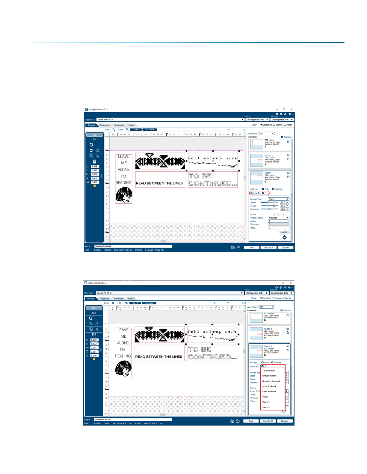
If you want certain proccesses to be engraved at the same time with the same settings, you may merge
them into one process. Click on the process you want to merge with other processes, then click on the
icon next to “Merge with”.
A list of processes will drop down, select a process to merge with by clicking on it.
- 57 -
Page 62

SECTION 5: THE LASER DASHBOARD
If you want to merge multiple processes all at once, hold down “ctrl” before clicking on multiple processes
in the list.
Once you let go of the “ctrl” button, all of the processes should be merged together as one process.
- 58 -
Page 63

SECTION 5: THE LASER DASHBOARD
Editing Artwork with Live View
Occasionally you may want to edit your engraving artwork to fit a uniquely shaped object. With the IRIS™
Camera on the Fusion Pro, you can copy the live preview image of your engraving piece and open it up
in your preferred graphic soware. From there you may adjust your graphic accordingly to the shape
of your engraving piece. In this example we will create a custom curve for text to follow, for engraving a
quote onto a clothes hanger.
1. First, place the object you want to engrave on the engraving table, then close the top door of the
machine.
2. Once the live preview of the table appears in the Dashboard, click on the “Copy Background
Image” button.
3. Open up your preferred graphic soware and paste the image into a new document, with the
table size as the dimensions of your document. In this example we used Corel Draw with the Fusion
Pro 32, so our document size is 32” x 20”.
Note: In CorelDraw you can lock the background image into place by right clicking on the
image and selecting “Lock Object”.
- 59 -
Page 64

SECTION 5: THE LASER DASHBOARD
4. To make our quote follow the shape of the hanger, we will need to trace the area we want to place
the text with the Freehand tool.
5. Once the tracing is finished, select the Text tool and move the mouse over the traced line until you
see a curved line icon appear. Click on the traced line when this icon appears.
- 60 -
Page 65

SECTION 5: THE LASER DASHBOARD
6. The text box will appear and anything typed out will automatically follow the path of the line.
Adjust your font face and size as needed.
7. Once your text is ready, select the line you used to curve the text with the Shape tool
8. Then click on the Pick tool
9. Select the text, go to File > Print and change the Print Range to “Selection”, then print to the Epilog
Engraver.
and hit “Delete” on your keyboard to remove the line.
- 61 -
Page 66

SECTION 5: THE LASER DASHBOARD
10. The text should now fit the shape of your engraving piece and be ready to print with your preferred
settings.
Saving Your Settings
You have two ways you can save settings for your jobs - by material and by job.
1. Settings by Material: Next to each process you will see a
small upload and download folder icon. These settings
will only aect the currently selected process.
• Import current material settings by clicking the folder
with the down arrow. Select between the Engrave and
Vector tabs, then choose your material from the list.
• Export your new material settings by clicking the folder
with the up arrow. Add a settings name and add it to an
existing folder.
• For step by step instructions see “Material Settings
Tab” on page 41.
2. Settings by Job: Your settings for the entire job can be saved by clicking on the folder icons at the
bottom of the Dashboard.
• Click the folder with the down arrow to import saved job settings.
• Click the folder with the up arrow to export your current job settings.
- 62 -
Page 67

SECTION 5: THE LASER DASHBOARD
• When is this helpful? When you have a series of processes you use frequently. For example, you
oen use a specific two-ply plastic for creating signs. You can save both your engraving and
vector processes.
• For step by step instructions, see “Job Settings Tab” on page 44.
File Settings
At the top of the Dashboard, you will see several file-related settings:
• Machine: Choose which laser you are sending the file to. This will show any lasers you have installed
in the Job Manager.
• Folder / Subfolder: Which folder and subfolder you want to save the file to in the Job Manager.
• View: This will change what portions of the graphic are shown in the preview. Choose to show all
processes (Combined), or just your Engrave or Vector processes. This is a good way to preview your
job and make sure you have set all of the lines you want to cut rather than engrave.
At the bottom of the page you’ll see several additional file settings:
• Name: Set your file name.
• Time: Displays the estimated time the project will take to run at the laser.
• Created / Printed: Displays the date and time the file was created and last printed.
• Print: Press the print button to send the job to the laser.
• Send to JM: Press this button to send the job to the Job Manager.
• Discard: Delete the file from the Dashboard.
- 63 -
Page 68

SECTION 5: THE LASER DASHBOARD
Settings in Detail
Resolution
Set your print resolution anywhere from 75 to 1200 DPI. For the best engraving results, use a resolution
equal to the resolution in the raster images within your project setup. We recommend using a resolution
of 400-500 for most standard engraving jobs. Use 600 DPI for jobs requiring finer detail. The resolution
setting in the print driver will aect the engraving time (there are twice as many engraved lines at 600 DPI
as at 300 DPI) and the quality. For a detailed discussion on Resolution, visit “Resolution” on page 81.
Engrave Direction
This feature applies to engraving only and allows you to engrave your project either from the top-down
or the bottom-up direction. In standard top-down engraving there can be a large amount of engraving
debris generated, especially on materials such as plastic, wood and rubber. As the debris moves toward
the exhaust plenum, some of it collects in the area that has just been engraved. Bottom-up engraving
prevents the debris from collecting in the freshly engraved spaces.
Process Type
Choose between the three modes of operation.
• O: This setting will tell the laser to ignore any items within this process.
• Engrave Mode: Used for engraving or marking materials. Typical uses include engraving clipart,
scanned images, photos, text and graphic images.
• Vector Mode: Selected when you are running only cut lines or for use with the Red Dot Pointer for
previewing the job processing area.
Speed
Determines the travel speed of the carriage and is adjustable in 1% increments from 1 to 100%. The slower
the speed, the deeper the engraving or cutting. Speed settings are heavily dependent on the hardness
and the thickness of the material being engraved or cut, with harder materials requiring slower speeds
for deeper engraving/cutting. Please refer to “APPENDIX B: MATERIAL SETTINGS” on page 129 in this
manual.
Power
Determines the amount of laser energy that is delivered to the piece being cut and is adjustable in
increments from 1 to 100%. The higher the power, the deeper the engraving/cutting. Please refer to
“APPENDIX B: MATERIAL SETTINGS” on page 129 in the manual.
- 64 -
Page 69

SECTION 5: THE LASER DASHBOARD
Frequency
The frequency setting is only active on vector processes, and controls the number of laser pulses that
the laser fires per inch of travel. The frequency is set in the dashboard and can be adjusted from 1 to
100%. A lower frequency number will have the eect of less heat because fewer pulses are being used to
cut the material. Lower frequency rates are helpful for products like wood, where charring is evident at
higher frequencies. High frequencies are useful on materials like acrylic where a large amount of heat is
desirable to melt or flame polish the edges.
Dithering
Dithering is used only for Raster engraving and has no eect on vector cut lines. This setting defines how
the dot patterns will be engraved in raster images that contain grayscale images, blends, or color. The
Dashboard oers six dierent dithering patterns to enhance your engraving projects. The default mode
is Standard. This mode can be used for all images including photographs, but some images improve
when engraved with other dithering patterns. For more information, go to “Image Dithering” on page
87.
Oset
Oset allows you to focus at any point above or below the suace of your material. When engraving
acrylic, many users like to focus above the suace to produce a “soer” finish to the engraving.
Conversely, when cutting acrylic, many users like to focus about half way into the acrylic. Oset allows
you to do this automatically. A positive value will move the table away from the focus lens. A negative
value, such as -.095, will move the table closer the focus lens.
- 65 -
Page 70

SECTION 5: THE LASER DASHBOARD
Processes Tab
The Processes tab is an alternative view of the various processes within your file. You can see each
process with the settings located next to the process without the video view of the table.
- 66 -
Page 71

SECTION 5: THE LASER DASHBOARD
Advanced Tab
On the Advanced tab, you can change settings that will aect the entire job. More features will be added
to this tab in the near future.
• Copies: Set the number of times you would like to rerun the job. If you have 2 processes, the laser
will complete each of the two processes, then run the two processes a second time. If you have a
process with more than one cycle (process 1: cycles 1, process 2: cycles: 2) and set the copies to 2, it
will run process 1 once, process 2 twice, then process 1 once again, and process 2 twice more. This is
useful when using the fiber laser with the system.
Notes Tab
Use the Notes tab to keep notes on running your file. This can include suggestions for artwork placement,
speed and power notes, or anything else a laser operator may find helpful when running that project.
- 67 -
Page 72

SECTION 5: THE LASER DASHBOARD
File Setup FAQs
I have a file with only cut lines, but they came in as an “Engrave” process.
How do I change it to a cut process?
Select the process and change the Process Type to “Vector”.
I merged two of my layers, but now it lost pa of the graphic.
Change the Process Type to “Engrave” and see if they show up now. It may have changed your process
to Vector and hidden any non-vector parts of your image.
I want to set up the Dashboard to automatically process all files I print to
the laser with hairlines as cut lines. How do I do this?
Go to the Settings icon and in the Dashboard tab, change your New Job Settings to “Split by Hairlines”.
I forgot to remove pa of the awork I don’t want to engrave. How do I get
rid of that pa of the file?
There are two ways to do this. Either ungroup your image, select the item and delete it, or separate it by
selection and turn that process to O.
Additional CorelDRAW Laser Dashboard Features
Each program you use will provide dierent ways to manage these functions. CorelDRAW oers a very
straight forward way to access each of these features.
Multiple Passes
You can automatically engrave or cut a job multiple times by setting the Number of Copies to the number
of passes that you want to make. When each pass is finished the laser will automatically start another
pass until all passes are complete.
Print Range
If you only want to print one aspect of your project (for example, just the text in the document), you can
select that part of the file, then click Selection and the laser will only engrave or cut that piece of your file.
Multiple Pages
When you want to engrave multiple pieces within one document, such as five dierent engraved glass
coasters, each with a dierent name, you can use the Multiple Pages feature of CorelDRAW. Set up each
of the coaster files on a separate page in your single CorelDRAW file, then when you print to the laser you
- 68 -
Page 73

SECTION 5: THE LASER DASHBOARD
can choose either Current document to print all of the pages or you can specify which pages you want
to print by adjusting the settings in the Print range box. You can view the dierent pages in the Print
Preview screen.
When a multiple page job is printed to the laser, each of the pages will transfer to the Control
Panel with the first file coming across as Job:1. File Name, then Job:2. Page 2, Job: 3. Page 3.
Remember, the last page of the job will be the current file when you go to the Fusion’s control
panel, so scroll back to Job 1: File Name to run that one first.
If you start engraving the jobs and become uncertain about which pages are which, you can refer back
to your print preview screen and the Page number in the laser will correspond to the page number in the
print preview.
- 69 -
Page 74

Page 75

SECTION 6: CONTROL PANEL
Display
The display shows valuable information associated with the highlighted Functional Menu items. We will
explain the dierent information that will be displayed as we go through the description of each menu
item.
Reset Speed
Focus Menu Power
Pointer Job Menu
Jog Menu Delete
Trace Settings Menu
Homing
Status Indicator
In the bottom le corner of the screen you will see text displaying the current status of the machine.
• Homing: This indicates the machine is still powering on. None of the functions are available until
powering on is completed.
• Idle: The machine is inactive and ready to run or resume a job.
• Running: A job is in progress when this is displayed.
• Parking: The axis is returning to Home position.
• Jogging: Jog mode is active.
Symbols
Go/Stop Button
Press the Go/Stop button to start and pause a job.
- 71 -
Page 76

SECTION 6: CONTROL PANEL
• Pressing the Go/Stop button during a running job will stop the lens carriage and the laser beam
will be shut o. If the Go/Stop button is pressed during raster engraving mode the lens carriage will
pause on either the far le or far right of the engraving line that is in process. If the Go/Stop button
is pressed while in vector cutting mode, the lens carriage will stop at the end of a line segment or at
the next line node location.
• Once the lens carriage has stopped, you can open the door to examine the job. By closing the
door and pressing the Go/Stop button, the job will commence where it le o. If the item being
engraved/cut has not been moved, the engraving/cutting registration will not be aected.
•
• If you press the Go/Stop button while in vector mode it may take some time for the system to
actually stop. The system needs to get to the next node in a vector before it can stop.
Note: Opening the door on the laser during engraving or cutting will stop the laser from
firing; however, the lens carriage will continue to move. It is important to stop the job
before you open the door to ensure the engraving/cutting is completed.
LED Status
The ring around the Go/Stop button will change certain colors depending on the Fusion Pro’s status.
• White: The machine is booting.
• Purple: The machine is waiting for the touch screen configuration to load.
• Multi-colored: The machine is Homing.
• Alternating Light Blue to Green: Machine is Idle and ready to run a job.
• Green: Machine is actively running or tracing a job.
• Red: A drive has failed. The number of flashes determines the drive number that failed. If more than
one drive has failed, it flashes for the first sequential drive.
• 1 - X Axis
• 2 - Y Le Axis
• 3 - Y Right Axis
Reset Key
• Pressing the Reset key will move the carriage back to its Home Position. Press the Reset
key aer you have moved the carriage when in Jog mode.
• You may also press this key if you want to start a job over aer pausing it with the Go/
Stop button. Reset does not erase the job from the laser systems memory; rather it will
stop the engraving job in process and send the carriage back to the Home Position.
Focus
The Focus function allows you to manually set the table to the correct height for engraving
while using the Focus Gauge. With Focus highlighted, use the Joystick to move the table up
or down. The display will show a digital readout of the table position. Press once to enable
the Focus feature and the icon will turn green. Press again to exit this feature.
- 72 -
Page 77

SECTION 6: CONTROL PANEL
Pointer
The Pointer key is a toggle switch that turns the laser system’s Red Dot Pointer on and o. For
more information visit ”Red Dot Pointer” on page 93.
Jog
The Jog function allows you to move the laser head around the table with the use of the
Joystick. To make it easier to use, turn on the Red Dot Pointer for a visual indicator of where
the carriage is moving. The carriage can be moved in X, Y or diagonally. The display will
show a digital readout of the carriage position. This function is useful for bringing the focus
gauge to any object on the table to ensure it’s focused properly. For more information see
“Auto Focus vs Manual Focus” on page 86.
Trace
The Trace function is a new feature that will be added soon. For now this key will be inactive.
Job Menu
Job-1
Job-2
Job-3
Idle
• The Job Menu allows you to scroll through the jobs in your laser system. You will be able to see a list
of jobs that have been sent to the laser. The job name displayed is the same as the file name that
you printed to the laser.
• When the job you want has been selected, it will be highlighted in blue. Press the Go/Stop button to
start the job.
• Aer the job starts, the job’s settings and a timer will be activated and will be shown at the bottom
of the display.
Job-1
Job-2
Job-3
Idle
Job-1
Engrave
50% 50% 600
Vector
50% 50% 50%
Idle
- 73 -
Page 78

Settings
+ System
Network
Idle
Park Axis Home Axis Home Table
+
SECTION 6: CONTROL PANEL
• Saved jobs will always be visible at the top of the list with a save icon next to the job name.
•
Pressing and holding down your finger on a job will pull up the job’s settings, allowing
you to view the Speed, Power, and Resolution or Frequency. A save button will also be
visible in the upper right corner that allows you to save the job permanently to the laser.
Speed
This icon indicates the speed settings on the selected job. It ranges from 1-100%.
Power
This icon indicates the power settings on the selected job. It ranges from 1-100%.
DPI
This icon indicates the resolution settings on the selected job. It ranges from 75-1200.
Frequency
This icon indicates the frequency settings on the selected job. It ranges from 1-100%.
Delete Button
The Delete Button will permanently erase jobs from the Job Menu. To
delete a job, select the job in the Job Menu, and then select the Delete
Button. A dialog will pop up to confirm that you want to delete the file.
Select “Yes” and the file will be removed from the Job Menu.
Note: If you have marked a job as “Saved” and delete the
file, it will still be erased from the Job Menu.
Job-1
Are you sure you want to delete this le?
Yes No
Idle
- 74 -
Page 79

SECTION 6: CONTROL PANEL
Settings/Config Menu
Settings
+ System
+
Network
Park Axis Home Axis Home Table
Idle
The Settings/Config menu has two sub-menus, System and Network Settings.
System
Once selected, the System Settings display detailed information about the machine. These are factory
settings that should not be changed unless instructed by Epilog Technical Support.
Network
Once selected, the Network Settings allow you to change the IP Address and the Netmask. The IP Address
on this screen should match the IP Address you have assigned your machine in the Job Manager. If you
have multiple machines, each one will need it’s own IP Address. For more information, see “6. Set the
Fusion Pro’s IP Address” on page 18.
Park Axis
Pressing Park Axis returns the Laser to the Home Position.
Home Axis
Pressing Home Axis repeats the Homing process that happens when the machine powers on.
Home Table
Home Table resets the table height to its Home Position.
- 75 -
Page 80

SECTION 6: CONTROL PANEL
Jog Menu
Access the Jog Menu by pressing the Jog key, which will turn green
when active. The Jog Menu allows you to adjust the current X and Y axis
positions of the laser head. You may change the current position of the
laser head either using the Joystick, or by entering precise coordinates.
The Nudge arrows allow you to fine-tune the position down to a
thousandth of an inch. Once you are finished using the Jog Menu, press
the Jog key again to return to the main Job Menu. Press the Reset key to
return the laser back to its home position.
Auto Focus
When you have jogged the lens carriage above your material, press
the Auto Focus button to use the pluger Auto Focus. The table will rise
until the material touches the plunger, then set the table to the correct
height. Your job should now be in focus.
Jog Axis
(inches)
Current Position
Nudge Amount:
< >
X:1.000 Y:1.000
Mo ve To
X: Y:
0.0 0.0
Jogging
0.005
Auto Focus
< >
Move
Done
Focus Menu
To access the Focus Menu press the Focus key, which turns green when
active. The Focus Menu is used for raising or lowering the table level to
focus the laser precisely to your engraving or cutting material using the
Focus Gauge. The height of the table is adjustable by either using the
joystick, or using the Nudge arrows to fine-tune the height down to a
thousandth of an inch. Once you are finished using the Focus Menu,
press the Focus key again to return to the main Job menu.
Home Table
Pressing the Home Table button resets the table height to its home
position, which is the default every time you turn on the machine.
Focus Menu
0.0
Focus
Idle
(inches)
Current Focus
0.000
Home Table
Nudge Table:Move Table
0.005
< >
Done
- 76 -
Page 81

SECTION 6: CONTROL PANEL
Joystick
The Joystick feature is used in Jog mode and Focus mode. The Joystick is progressive and touch sensitive
and provides a continuously variable range of adjustments. It is sensitive to the degree of tilt that is
being applied. The more you tilt the Joystick, the bigger your impact on the function you are using.
Job Storage
The Fusion Pro has 1 GB of permanent storage. While powered on, the machine will store any and all jobs
sent until there is no free memory le. This feature allows you to save your most run jobs right at the laser
without needing to first print them from the computer.
To save a job, press and hold down on a job in the Job Menu until it pulls up the job’s settings. Select
the save button in the upper right corner and the job will save permanently to the laser until manually
deleted. If you do not save a job, it will be deleted upon powering down the machine.
- 77 -
Page 82

Page 83
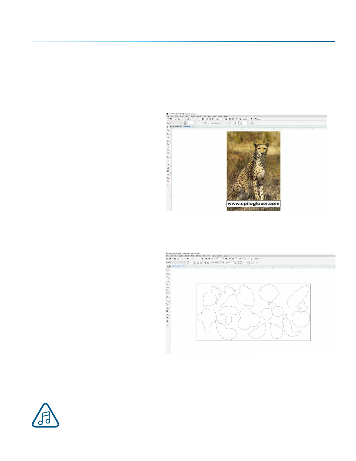
SECTION 7: QUICK START GUIDE
Artwork Setup
Create your job in the graphics soware of your choice, such as CorelDraw or Adobe Illustrator. There are
three dierent modes of operation for the laser and the way you setup your artwork will determine if you
raster engrave, vector cut, or use combined mode.
Raster Engraving
Raster engraving can best be described as
very high resolution dot matrix “printing”
with a laser. Raster engraving is used to
create highly detailed graphic images. The
laser head scans back and forth, le to
right, engraving a series of dots one line at
a time. As the laser head moves down line
by line, the dot pattern forms the image
that was printed from your computer. You
can raster engrave scanned images, text,
clipart, photographs, or line drawings.
This artwork is a good representation of a raster file. The photograph of the leopard will raster engrave,
as will the text that has been placed on the page. For more information on engraving photographs, see
“PhotoLaser Plus” on page 98.
Vector Cutting
When you are vector cutting, the laser is
following a continuous path that follows
the outline or profile of an image. Vector
cutting is normally used to cut completely
through materials such as wood, acrylic,
paper, etc. It can also be used for quick
marking of characters and geometric
patterns. You can vector cut with the laser
by setting objects and text to be unfilled
and drawn with a 0.003” (0.0762 mm) or
less outline. The thin outline will produce a
vector cut.
This graphic shows a vector image made up of lines. You can tell it is a vector image because you can
individually select any of the points on the lines and manipulate that part of the graphic.
When vector cutting, we always suggest that you use the Vector Cutting Table or the Slat Table to protect
the back of your material as well as your table from laser marking. For more info, see “Vector Cutting
Table” on page 97.
Note: If your raster artwork contains thin lines between .001” (.025 mm) and .003” (.177 mm)
depending on resolution, and you are using Vector or Combined mode, those thin lines will all
vector cut. The most common setup where this occurs is when you have a clipart image with
- 79 -
Page 84

SECTION 7: QUICK START GUIDE
hidden lines that you send to the laser using Combined mode. The artwork shown below is a good
example of a piece of clipart as it appears on the screen (top) and the hidden lines (bottom) that will
vector cut if you are in Combined or Vector mode. If you only want to raster engrave, make sure you
select Raster mode in the Epilog Dashboard.
In CorelDraw you can view just the lines (bottom view) by clicking on the View key in the menu bar and
selecting Simple Wire Frame. The upper image is a complex piece of clipart. The lower image shows all of
the hidden lines that are in this piece of clipart. If this clipart image were run in Combined mode, it would
first raster engrave most of the elephant then vector cut any of the thin lines below .003” (0.077 mm) in
CorelDraw, or .001” (0.025 mm) in Adobe Illustrator. You can also use the Preview function of the Epilog Job
Manager to view only vector lines. See “Previewing Your Job” on page 38.
Clipart that looks like it is a
raster file is actually oen
made up of small lines. If the
lines are set too thin, then it
may cut as well as engrave
if you send it to the laser in
combined mode.
Setting a Vector Cutting Line
With the new Job Manager you have many options for setting your Vector Cutting lines. The easiest way
to do it is by line width, but you may also set it to Vector by a specific color or by selecting the individual
processes in the Job Manager that you want to cut instead of engrave. The key is to be consistent in
which method you pick to avoid confusion.
- 80 -
Page 85

SECTION 7: QUICK START GUIDE
Where do I set the Vector Line Width?
Dierent soware packages set the line width in dierent places. In CorelDRAW, you can find the outline
width in the top menu bar when a vector line is selected. In Adobe Illustrator it is called the stroke width
and you can find this setting in the Stroke Panel. Vector line width will vary from program to program. We
find that using .003” (0.077 mm) or less in CorelDraw, or .001” (0.025 mm) or less in Adobe Illustrator works
best.
If you can’t select a line to set the width, it may be because it is part of a grouped object. Try
to ungroup the object, then select the line. You also can’t select an individual line if that line is
part of a raster image.
Resolution
Print quality is commonly referred to as Resolution and is one of the variables that determine image
quality. Resolution is expressed in dots per inch (DPI) and is determined by the number of lines or dots
that are engraved for every inch of movement. Each horizontal line is referred to as a raster line. The
higher the resolution setting, the finer the detail that can be achieved. Keep in mind that engraving
resolution is only one factor in determining image quality. The quality of the artwork being sent to the
laser can have a bigger influence on the look of the final product than the resolution. If low quality
artwork is being used, even the highest resolution will not improve it. Also keep in mind that image quality
is subjective. 300 DPI may be just fine for some images and some customers, while 600 DPI is the absolute
minimum for others.
This diagram shows the concept
of raster lines and dots-per-inch
(DPI). The arrows show the change
in direction of the carriage between
raster lines. The dierence in dot
density between 300 DPI and 600 DPI.
300 DPI 600 DPI
- 81 -
Page 86

SECTION 7: QUICK START GUIDE
Resolution Settings:
75 – 200 DPI
These resolution values are typically used for non-production purposes where you want to experiment
with image location, or if you want to quickly produce a rough dra. Low resolution settings are also
useful when engraving products that you don’t want to remove too much material from while engraving,
such as fabric.
300 DPI
300 DPI is useful when engraving materials such as glass, marble, plastic and other items that don’t
benefit from the engraved dots being close together.
400 DPI
This resolution value is ideal for many applications. It combines very good image quality with fast
engraving times. Many users like 400 DPI for all of their work.
600 DPI
When really fine detail or overall excellent results are required, most users choose 600 DPI.
1200 DPI
This resolution is used for projects that require the best engraving quality possible, or if engraving
extremely small fonts. Although it’s seldom used because, under normal circumstances, most people
cannot visually discern the dierence between 1200 and 600 DPI. There are some users that appreciate
this high level of quality and are willing to take twice as long to produce an image at 1200 DPI as it would
take them at 600 DPI.
Helpful Hints
• There are four times as many dots engraved at 600 DPI as there are at 300 DPI. Twice as many
horizontally and twice as many vertically.
• The gap between the dots is very small at 600 DPI. At 300 DPI the lesser overlap is responsible for the
jagged edges that are visible when engraving at lower resolutions.
• It’s important to remember that while resolution plays a part in producing good image quality, the
artwork that is sent to be engraved is just as important. If the artwork that is sent to the laser is
poor quality, trying to engrave it at 600 DPI will not improve the quality. It’s always best to start with
high resolution images. Poor artwork will probably always look poor at any resolution, while good
artwork will look good at any resolution.
• Twice as many dots and twice as many lines at 600 DPI produces a much deeper burn into
materials like wood than you would see engraving the same image at 300 DPI. This is important to
understand because depth of burn is closely associated with engraving resolution – the higher the
resolution, the greater the depth of burn for a given speed. The relationship between resolution,
depth of engraving and Speed and Power setting is something that most people figure out with
just a little experience. “APPENDIX B: MATERIAL SETTINGS” on page 129 helps to make this easy to
understand by providing dierent Speed and Power settings and suggested engraving resolutions
for each dierent material listed.
The next photo shows a clipart image engraved at 300 DPI (top) and at 600 DPI (bottom). This clipart image
is full of dierent shades of gray and you can see that the dot spacing is spread out more on the 300
DPI than it is on the 600 DPI. Just changing the resolution to 600 DPI produces so much dot overlap that
- 82 -
Page 87

SECTION 7: QUICK START GUIDE
the fill patterns tend to blend together. It’s a matter of personal preference as to which resolution looks
better, but these photos show the dramatic dierence resolution can make, especially when engraving
with grayscale images.
Landscape or Portrait
You can engrave using either landscape or portrait modes. Depending on the artwork, you
can increase your eiciency and decrease the time it takes to engrave an image by changing
the orientation of your file. Many users set up their artwork in portrait mode and then rotate
the artwork 90 degrees if they are going to print from landscape mode.
300 DPI
600 DPI
This project setup shows the same job in portrait mode (le) and landscape mode (right). The landscape
mode will engrave quicker because there is less turnaround time as the laser makes longer passes across
the engraving table. For example, at 100% speed and 100% power in portrait mode this graphic will take
56 minutes, 56 seconds, while in landscape mode it takes 38 minutes, 54 seconds, a 34% time savings.
Engraving Time: 56:56
Engraving Time: 38:54
- 83 -
Page 88

SECTION 7: QUICK START GUIDE
The drawings below show a job that works in the opposite way - the horizontal mode will take longer
than the portrait mode. You’ll notice in the portrait mode there are a number of white space lines that the
laser can skip through, saving engraving time. In the landscape mode there is not white space for the
laser to recognize as it moves down the page, taking the engraving time from 10:12 to 17:14. Experiment
with the artwork that you use. It will quickly become second nature which mode works best for dierent
types of artwork.
Engraving Time: 10:12
Engraving Time: 17:14
A third consideration for landscape or portrait art setup is material specific. Some materials, such as
wood or plastics that have a grain or brushed look, will look better when engraved if the grain of the
material runs parallel with the X-stroke of the carriage. While the orientation of material without a grain
pattern is usually not important, it is important to keep this in mind with woods that have a stronger grain
pattern.
Preferred
Travel direction of carriage
Wood Grain
Less Desirable
Wood Grain
- 84 -
Page 89

SECTION 8: SYSTEM FEATURES
IRISTM Camera Positioning System
The Fusion Pro includes the IRISTM Camera Positioning System which
allows you to precisely place your artwork on screen in seconds.
The overhead camera(s) provide a live picture of the working area
for accurate artwork placement, and a camera at the lens allows
the system to find preprinted registration marks. Your Fusion Pro
will either have 1 or 2 overhead cameras, depending on whether
you have the 32 or 48 model.
Using the IRIS™ Camera
The live preview of your projects can be viewed within the Epilog Dashboard under the Preview tab.
The IRIS™ Camera Positioning System will provide the most accurate results when the piece being cut
or engraved is placed directly underneath the camera(s), and the table level is focused to the piece.
If the piece is not in focus on the table, the artwork may not be aligned properly in the live preview.
The camera(s) may also be calibrated for improved accuracy. For more information, see “Camera
Calibration” on page 136.
Note: The top door of the Fusion Pro must be completely shut to use the live preview in the
Epilog Dashboard.
Touch Screen
The laser of the Fusion Pro is controlled by a 7” capacitive
resolution touch screen. This feature allows you to select between
jobs, change settings, and more. For more information on how to
use the touch screen, see “SECTION 6: CONTROL PANEL” on page
71.
- 85 -
Page 90

SECTION 8: SYSTEM FEATURES
Air Assist
The Air Assist feature on the Fusion Pro Laser is used to keep
combustible gases away from the cutting suace and to reduce
flare-ups of more flammable materials as you cut through it,
such as wood and acrylic.
The Air Assist directs a constant stream of compressed air across
the material suace at the point of burn removing the heat and
combustible gases from the work suace. The constant air stream
helps reduce charring and scorching associated with materials,
such as wood, rubber, and acrylic. The Fusion Pro systems also
include an air compressor within the machine.
The Fusion Pro systems have two types of Air Assist:
• Cone: This feature directs air through the cone shaped part
of the assembly, and permanently remains on while running any
job to help keep the lenses clean.
• Sweep: This feature directs air through the Air Assist tube to
the side of the cone. This feature has the option to be turned on
or o by the switch directly on top of it.
Both types of Air Assist should always be activated during vector cutting operations to reduce the risk of
fire! For more information, see “FIRE WARNING” on page 1 of the manual.
Auto Focus vs Manual Focus
In order to engrave or cut a crisp, clean image, your material must be the correct distance from the
bottom of the focus lens. Setting the distance from the bottom of the focus lens to the top of your material
is the process of focusing, and is accomplished by placing your material on the table and moving the
table up or down.
Auto Focus
When you enter Jog mode and have jogged the lens carriage above your material, press the Auto Focus
button to use the pluger Auto Focus. The table will then rise until the material touches the plunger, then
set the table to the correct height. Your job should now be in focus.
Manual Focus
This photo shows the manual focus gauge that is used to determine the correct distance from the focus
lens to the top of your material. This gauge is included with your system.
Place the object to be cut or engraved anywhere on the table of the machine. Select the Jog
button on the touch screen and use the Joystick to bring the focus gauge to the object. Deselect
the Jog button, then select the Focus button on the touch screen and move the Joystick up or
down to move the table appropriately until your material just touches the bottom of the gauge.
The speed at which the table rises or lowers can be controlled by applying varying pressure upwards or
downwards on the Joystick. You may also fine-tune the table height in the Focus Menu. Once the focus
- 86 -
Page 91

SECTION 8: SYSTEM FEATURES
position has been established, flip the gauge back up into its locked position. Press the Focus button to
leave the menu and then press the Reset key to bring the laser head back to its Home Position.
If your material has a taper or curve, pick an intermediate point between the highest and lowest points
being engraved and focus on that point. In general, the area of the material being engraved needs to be
relatively flat. If the area being engraved diers in height by more than about an .125” (3 mm), the image
will begin to look “fuzzy” or out of focus.
Key Switch
The Key Switch feature is used to power the Fusion Pro on and o, and
also allows you to lock out any unauthorized users by powering down
the machine and removing the key.
Image Dithering
Dithering defines how the dot patterns will be engraved in raster images that contain grayscale graphics,
blends, or color images. The Dashboard oers six dierent dithering patterns to enhance your engraving
projects. The default mode is Standard. This mode can be used for all images including photographs.
Dithering is used only for raster engraving and has no eect on vector cut lines.
Laser engraved photographs on wood usually require a third party soware package to
produce a good image that is suitable for the laser. Epilog recommends PhotoLaser Plus for
this application. Users find it an invaluable piece of soware that is easy to use and will
produce much better looking images when working with wood. Please contact your Epilog
representative to learn more about this soware package. For more information on using
PhotoLaser Plus, see “PhotoLaser Plus” on page 98.
What is Dithering?
300 DPI Standard Mode
The best way to show dithering is to look at the exact same photo engraved in Standard mode and Stucki
mode. Both photos were engraved at 300 DPI. With the two dierent dithering patterns you achieve a
very dierent result, with a more structured pattern for the Standard mode, while the Stucki mode results
in a more random pattern that looks more natural and pleasing to the eye.
300 DPI Stucki Mode
- 87 -
Page 92

SECTION 8: SYSTEM FEATURES
Dithering is a great way to enhance your engraved products, but it is very material dependent. A dithering
pattern that looks good on marble, might look very dierent when engraved on plastic. Give yourself
some time to experiment with the dierent dithering patterns. It’s easy to do and once you have a feel
for it, you will be able to use it with confidence
The drop-down list of dithering patterns is easier to think about if you separate the six options into two
categories that we will refer to as Clipart and Photograph:
Clipart Modes
• Standard: This mode is the default mode and will be used
for most engraving jobs that include text and clipart at
600 DPI.
Photograph Modes:
• Floyd-Steinberg: Produces an almost wave-like pattern
to an image. This works well for some photos containing
a great deal of detail. Photos with more monotone
swatches of color may not be as pleasing as Jarvis or
Stucki modes.
• Jarvis: Many users find this mode good for engraving
photographs at 300 DPI. This mode produces a very nice
looking pattern on almost all photos.
• Stucki: This mode produces results that are only
marginally dierent than the Jarvis dithering pattern. It is
also very good for engraving photographs at 300 DPI. The
dierences between Jarvis and Stucki are very subtle.
- 88 -
Page 93

SECTION 8: SYSTEM FEATURES
• Bayer: This mode is an eicient and widely used
haloning technique. It is easily distinguished by its
noticeable crosshatch patterns. Bayer (ordered) dithering
is more suitable for line-art graphics.
Experiment with the dierent dithering patterns to determine which eect is most pleasing. It is not
mandatory that you use the clipart modes with only clipart images or photograph modes with all
photographs. Many users prefer one of the photograph modes for many clipart images, and one of the
clipart modes for photographs. The choice is entirely up to you and will take some experimentation.
Color Mapping
Using Color Mapping
When the “Split By Color” option is selected, the graphic’s single process will split into separate processes
by each color, allowing you to apply each color’s settings individually. The laser will then use the settings
assigned to each color.
- 89 -
Page 94

SECTION 8: SYSTEM FEATURES
Color Map Settings
The Color Map Settings can be found under the Processes section located on the right side of the window,
which lists of all of the color mapped processes.
1. Select a color in the Processes area. We selected the color Yellow. Once selected your laser
settings will be revealed.
2. Adjust the laser settings on the selected process.
3. Once the laser values have been adjusted, you may select any other color processes that need to
be changed.
4. When any process tabs are collapsed, you can still see their speed and power settings displayed
under each process name.
Color Mapping Functions
Engrave: Setting a specific color process to Engrave means the laser will apply the same engraving
settings to all objects set to that color.
Vector: Setting a specific color process to Vector means the laser will apply the same vector settings to
all objects set to that color.
Speed: Applies a speed setting for all objects of the same color.
Power: Applies a power setting for all objects of the same color.
Frequency: Applies a frequency setting for all objects of the same color (Vector only).
Oset: Oset allows you to focus at any point above or below the suace of your material. When
engraving acrylic many users like to focus above the suace to produce a “soer” finish to the engraving.
Conversely, when cutting acrylic, many users like to focus about half way into the acrylic. Oset allows
- 90 -
Page 95

SECTION 8: SYSTEM FEATURES
you to do this automatically. A positive value will move the table away from the focus lens. A negative
value, such as -.095, will move the table closer the focus lens.
Using Color Mapping for Multiple Speed and Power Settings
A fairly typical use for vector color mapping is in the architectural industry and making models. Users
want to lightly mark one part of the work piece and cut out another part of the same piece.
Usually, when using Color Mapping in Vector mode, users want to produce a dierent look on two separate
areas of a single piece of material in a single job setup. To achieve a dierent look for each mark the
marking processes require dierent speeds and powers so this is a peect job for Color Mapping.
Note: While you could set the vector line you want to just mark to an engraving width, it takes
much longer to engrave a box than to use vector settings to quickly follow the line and mark
it.
The graphic shows a simple architectural drawing. The drawing is set up so that when we use Color
Mapping, we can assign one speed and power setting to first lightly engrave the window frames and a
dierent speed and power setting to then cut out the individual window panes.
Once you have split the graphic by color, the outside frame of the house will become one process, and
the window frame and window panes will be individual processes as well.
You can use any colors you like for color mapping and are not restricted to using RGB or
CMYK colors.
- 91 -
Page 96

SECTION 8: SYSTEM FEATURES
1. Make sure to select Split By Color so we can set up our color mapping settings.
2. In our example we want to mark the green portion of the graphic first, so green must be the first
color at the top of the list. In order to move it we just click and hold the process while dragging it up
to move it up to the top position. We now have green at the top and red is the second color down.
This is the order that the colors will be processed.
3. With the green color selected, we set a higher speed and lower power (50% speed, 10% power) to
just mark the top of the piece. When you have your settings as you’d like them.
4. Repeat by selecting the Red color in the summary area, then adjusting the speed to 20% and power
to 100%.
Using Color Mapping to Adjust Object Order
Another popular use for color mapping is to adjust the order a series of objects engraved or cut. In the
example below, there are three columns of names we are engraving. If we engrave the le file in the
image below, the laser carriage will have to travel all the way across the table, covering a lot of empty
space, to engrave the image.
If we adjust the colors in each bar, we can setup the color mapping to engrave first the red
bar, then the green bars in the center, and finally engrave the blue bar on the right side of the
page. The engraving time drops from 39:09 to just 22:14 by using Color Mapping in the file
setup.
Engraving Time: 39:09
Engraving Time: 22:14
- 92 -
Page 97

SECTION 8: SYSTEM FEATURES
Additional Color Mapping Notes
• When color mapping is used, it always starts from the top color in the Map List and then descends
through the remaining colors.
• There’s one important distinction to recognize about how colors are raster engraved in standard
engraving mode vs. Color Mapping mode. In standard engraving mode dierent colors are
interpreted as dierent shades of gray that will produce dierent fill patterns when engraved. In
Raster Color Mapping mode all of the dierent colors are engraved as if they have a black fill. There
is no way for a color to produce both a fill pattern and be color mapped at the same time.
Non-Mapped Colors
Non-mapped colors will be processed last and will be processed using the Speed and Power settings
from the General tab. An example would be artwork that has black lines as well as the red and green we
are mapping. The black lines will be processed last at the speeds and powers that are set in the General
tab.
Color Mapping in Combined Mode
Color Mapping in combined mode requires a little more planning than Raster only or Vector only modes.
1. Any object that is color mapped will be raster engraved first in the order the colors appear in the
Summary section of the tab. Any other raster objects that are not color mapped will then be raster
engraved using the raster settings found in the General Tab.
2. Aer all of the raster objects have all been engraved, the vector objects will be vectored in the
order they appear in the Summary section of the tab. Any other vector objects that are not color
mapped will then be vectored using the vector settings found in the General Tab.
For most jobs, Color Mapping is a poweul and easy tool to use and understand. Please keep
in mind that because you can control seven dierent variables and 17 dierent colors doesn’t
mean that you should. With so many dierent settings available in a single setup it has the
potential to get overly complicated. Sometimes it’s easier to scale back on how many colors
a job should use.
Red Dot Pointer
The Red Dot Pointer is a visible laser beam that runs in the same line as the invisible CO2 laser beam. It is
useful for showing the location of the laser head when using Jog or Focus mode.
- 93 -
Page 98

SECTION 8: SYSTEM FEATURES
Emergency Stop Button
On the top of the laser you will see a large, red Emergency Stop
key. If there is an emergency, such as a fire, immediately press the
Emergency Stop Button. The laser carriage will immediately stop
and the system will shut down.
To reset the system, you must turn o the system using the Key
switch, then twist the Emergency Stop Button clockwise to release
the system, then turn on the laser.
If your laser ever stops running and you can’t turn it on, check to see if the Emergency Stop
Button has been pressed by accident.
Front Access Door
The front access door will open up to 180 degrees,
and is usually used for easy loading and unloading of
palletized materials. The door is interlocked and the
laser will not fire if the door is open.
Task Plate/Vacuum Hold-Down Table
Task Plate
On the Fusion Pro, the task plate is used as the
standard engraving table for jobs that do not include
vector cutting. The task plate is stainless steel and
allows you to use magnets to hold oddly shaped
items in place. On the Fusion Pro 48 there are two
taskplates, allowing you the option to split your
table to both engrave and cut materials in the same
process with a Vector Grid or Slat Table.
- 94 -
Page 99

SECTION 8: SYSTEM FEATURES
Vacuum Hold-Down Table
The holes in the task plate provide vacuum hold-down capability that keeps thin materials flat while
engraving. The exhaust system is designed so that it evacuates from both the top and the bottom of the
task plate when the task plate is at its highest position. The exhaust pulls air through the holes and forms
enough of a vacuum that it will flatten slightly warped paper, wood, aluminum sheet stock and other
materials. As long as the exhaust is operating and the task plate is no more than an inch (25.4 mm) below
its highest point, the vacuum table will work.
If you have a piece of sheet stock that does not flatten out because it is not covering enough
of the vacuum holes, you can use any material (including paper) to cover some of the exposed
holes. Simply blocking most of the vacuum holes will be enough to flatten most sheet stock
as long as it is not too severely warped, bent or too rigid. Magnets can be used to hold oddly
shaped items in place if needed.
Exhaust Plenum
The Fusion Pro incorporates an exhaust plenum and an integrated Vacuum hold-down table. Both the
exhaust plenum and the hold-down table use the ailow from the exhaust fan for two distinct functions.
1. Exhaust Plenum: The exhaust fan moves air from the front towards the rear of your machine and
out the exhaust plenum. This air removes combustible gases and smoke through the exhaust
plenum. The Fusion Pro has risers underneath the task plate(s) with funnels that are larger toward
the front of the machine and smaller toward the back of the machine to provide uniform air flow
through the entire table area. There is one exhaust port at the back of the Fusion Pro 32 and two at
the back of the Fusion Pro 48.
2. Vacuum Hold-Down Table: There is a single exhaust port on the back of the Fusion Pro 32 and 48
that pulls air down through the table.
- 95 -
Page 100

 Loading...