

Page 1
OWNER'S MANUAL FOR EPILOG
Fusion - MODEL 13000
This manual can also be found in electronic format on the
Epilog Dashboard Drivers and Documentation
disk that came with your laser system.
April 17, 2013
16371 Table Mountain Parkway
Golden, CO 80403
Phone (303) 277-1188
Fax (303) 277-9669
Technical Support Direct Line: (303) 215-9171
Email Technical Support: tech@epiloglaser.com
Technical Support Online:
www.epiloglaser.com/service.htm
www.epiloglaser.com/downloads.htm
Page 2

THIS PAGE WAS
INTENTIONALLY LEFT BLANK
ii
Page 3

Contents at a Glance
Fire Warning!.........................................................................................i
Introduction ........................................................................................ xi
Epilog Laser Setup...............................................................................1
Section 1: Safety ............................................................................................................................ 1
Section 2: Dos and Don’ts ........................................................................................................... 13
Section 3: Getting Started .............................................................................................................. 1
Section 4: Installing the ECC (Epilog Control Center) ............................................................... 12
Section 5: Installing the Epilog Dashboard Print Driver ............................................................. 22
Section 6: Using the Epilog Dashboard....................................................................................... 47
Basic Operations................................................................................79
Section 7: Quick Start & Easy Setup ........................................................................................... 81
Section 8: Using the Front Control Panel .................................................................................... 91
Section 9: Using the ECC (Epilog Control Center).................................................................... 101
Section 10: Standard & Optional Machine Features.................................................................. 107
Section 11: Engraving Machine Cleaning ................................................................................. 119
Section 12: Speed and Power Recommendations...................................................................... 131
Section 13: Material Engraving Techniques.............................................................................. 139
Section 14: Material Suppliers................................................................................................... 155
Technical Support, Troubleshooting and Specifications...................161
Section 15: In Case of Difficulty ............................................................................................... 163
Section 16: Specifications.......................................................................................................... 165
Section 17: Upgrading the Operational Firmware ..................................................................... 171
APPENDIX A WARRANTY STATEMENT ...............................................177
APPENDIX B PRINTING FROM AUTOCAD...........................................179
APPENDIX C ADDITIONAL DASHBOARD PRINT DRIVER INSTRUCTIONS
........................................................................................................183
INDEX...............................................................................................195
iii
Page 4

Contents at a Glance
THIS PAGE WAS
INTENTIONALLY LEFT BLANK
iv
Page 5

Table of Contents
Fire Warning!.........................................................................................i
Introduction ........................................................................................ xi
How to Use This Owner’s Manual ........................................................................................ xi
Epilog Laser Setup...............................................................................1
Section 1: Safety ............................................................................................................................ 1
Laser Safety ............................................................................................................................ 1
Electrical Safety ...................................................................................................................... 3
Fire Safety............................................................................................................................... 4
Safety Features and Regulatory Compliance.......................................................................... 5
Section 2: Dos and Don’ts ........................................................................................................... 13
DON’T!................................................................................................................................. 13
DO......................................................................................................................................... 14
Section 3: Getting Started .............................................................................................................. 1
Setting Up Your Laser System ............................................................................................... 1
Connecting the Exhaust ..........................................................................................................7
Connecting Electrical Power................................................................................................... 9
Section 4: Installing the ECC (Epilog Control Center) ............................................................... 12
USB Port ............................................................................................................................... 17
Ethernet Port ......................................................................................................................... 17
Section 5: Installing the Epilog Dashboard Print Driver ............................................................. 22
Installing the Dashboard Driver Using the USB Connection using XP or Vista.................. 23
Installing the Dashboard Driver Using the USB Connection using Windows 7 or 8........... 23
Installing the Dashboard Driver Using an Ethernet Connection and a Crossover Cable ..... 33
Section 6: Using the Epilog Dashboard....................................................................................... 47
Additional Dashboard Driver Features ................................................................................. 75
Changing Dashboard Driver Defaults................................................................................... 77
v
Page 6

Table of Contents
Basic Operations................................................................................79
Section 7: Quick Start & Easy Setup ........................................................................................... 81
Artwork Setup....................................................................................................................... 81
Job Setup............................................................................................................................... 84
Section 8: Using the Front Control Panel .................................................................................... 91
Section 9: Using the ECC (Epilog Control Center).................................................................... 101
Job Tab................................................................................................................................ 101
Configuration Tab............................................................................................................... 105
Section 10: Standard & Optional Machine Features.................................................................. 107
Air Assist ............................................................................................................................ 107
Front Access Door .............................................................................................................. 108
Task Plate............................................................................................................................ 109
Optional Vector Grid/Vacuum Hold-down Table .............................................................. 109
Pin Table ............................................................................................................................. 113
Section 11: Engraving Machine Cleaning ................................................................................. 119
This cleaning section may show photos of other Epilog machines. The cleaning process is
the same so please use these photos as a reference guide................................................... 119
Cleaning - Important!............................................................................................................... i
Fire Warning!...................................................................................................................... 119
Laser Tube .......................................................................................................................... 129
Section 12: Speed and Power Recommendations...................................................................... 131
Engraving Speed ................................................................................................................. 131
Engraving Power................................................................................................................. 131
Recommendations............................................................................................................... 132
Multiple Passes ................................................................................................................... 133
30 Watt................................................................................................................................ 134
40 Watt................................................................................................................................ 135
50 Watt................................................................................................................................ 136
60 Watt................................................................................................................................ 137
75 Watt................................................................................................................................ 138
vi
Page 7

Table of Contents
Section 13: Material Engraving Techniques.............................................................................. 139
Acrylic...................................................................................................................................... i
Fire Warning!...................................................................................................................... 139
Anodized Aluminum........................................................................................................... 142
Brass - Painted .................................................................................................................... 142
Glass.................................................................................................................................... 144
Notary Seals - Delrin .......................................................................................................... 146
Plastic.................................................................................................................................. 147
Rubber Stamps .................................................................................................................... 149
Wood................................................................................................................................... 149
Section 14: Material Suppliers................................................................................................... 155
Technical Support, Troubleshooting and Specifications...................161
Section 15: In Case of Difficulty ............................................................................................... 163
Contacting Technical Support............................................................................................. 163
Section 16: Specifications.......................................................................................................... 165
Epilog Fusion 32 x 20 Specifications ................................................................................. 165
Compatibility ...................................................................................................................... 166
Recommended PC............................................................................................................... 166
Other Computer Hardware Recommendations................................................................... 168
About The Laser ................................................................................................................. 168
Federal Communications Commission (FCC) Notice ........................................................ 169
Section 17: Upgrading the Operational Firmware ..................................................................... 171
Upgrading Your Firmware.................................................................................................. 171
Installing New Firmware onto Your Computer .................................................................. 172
Transferring New Firmware from Your Computer to Your Laser ..................................... 174
APPENDIX A WARRANTY STATEMENT ...............................................177
APPENDIX B PRINTING FROM AUTOCAD...........................................179
APPENDIX C ADDITIONAL DASHBOARD PRINT DRIVER INSTRUCTIONS
........................................................................................................183
Windows 7: Setting up the TCP/IP Address in the Computer........................................... 183
Windows 8: Installing the 64-bit Epilog Dashboard Print Driver in Windows 8.............. 189
vii
Page 8

Table of Contents
INDEX...............................................................................................195
THIS PAGE WAS
INTENTIONALLY LEFT BLANK
viii
Page 9

Fire Warning!
Your laser system uses a high intensity beam of light that can generate extremely
high temperatures when it comes into contact with the material being engraved,
marked or cut. Some materials are extremely flammable and can easily ignite and
burst into open flame setting the machine afire. This open flame is very
dangerous and has the potential to destroy not only the machine, but the building
in which it is housed.
Experience shows that vector cutting with the laser has the most potential to
create an open flame. Many materials are susceptible to igniting, but acrylic, in
all its different forms, has been shown to be especially flammable when vector
cutting with the laser.
Please read the following warnings and recommendations and follow them closely
at all times!
NEVER let the laser system operate if it will be unattended.
KEEP the area around the machine clean and free of clutter, combustible
materials, explosives, or volatile solvents such as acetone, alcohol, or
gasoline.
ALWAYS keep a properly maintained and inspected fire extinguisher on
hand. Epilog recommends a Halotron fire extinguisher or a multi-purpose
dry chemical fire extinguisher. The Halotron extinguishers are more
expensive than a dry chemical, but offer certain advantages should you
ever need to use an extinguisher. The Halotron extinguisher discharges a
clean, easily removable substance that is not harmful to the mechanics or
wiring of the laser system. The dry chemical extinguisher discharges a
sticky, corrosive powder that is very difficult to clean up.
ALWAYS use air assist when vector cutting.
BE CAREFUL! when vector cutting. Many materials have the potential
to burst suddenly into flames – even materials that may be very familiar to
the user. Always monitor the machine when it is operating.
KEEP YOUR LASER SYSTEM CLEAN – A build up of cutting and
engraving reside and debris is dangerous and can create a fire hazard in its
own right. Keep your laser system clean and free of debris. Regularly
remove the vector grid to clean any small pieces that have fallen through
the grid.
ix
Page 10

Fire Warning!
SEE PREVIOUS PAGE
x
Page 11

Introduction
How to Use This Owner’s Manual
Thank you for purchasing an Epilog Fusion Laser System. Your Epilog system
has been designed to be easy to operate, but you will utilize it to its fullest
potential by taking some time to read this owner’s manual prior to use. You will
be ready to use the Epilog laser system as soon as you read the first six sections.
Then you can refer to topics in the remaining sections, as you work.
Structure of the Manual
Part I: Setup
Sections 1 through 6 explain how to uncrate and set up your Epilog system,
important safety information you need to know before you use it, the Do’s and
Don’ts of operating the laser, configuring your computer to run the Epilog
Dashboard print driver, configuring CorelDraw, and a brief user’s guide to
running your first job.
Part II: Basic Operations
Sections 7 through 14 explain Using the Epilog Dashboard Print Driver, basic
Epilog laser operations and maintenance, machine features, speed and power
recommendations, material engraving techniques, and material suppliers.
Part III: Troubleshooting, Service and Specifications
Sections 15 through 17 assist with problem troubleshooting, service information;
system specifications and firmware upgrade instructions.
APPENDIX A
Epilog Warranty Information.
APPENDIX B
Printing from AutoCAD.
APPENDIX C
Additional Dashboard Print Driver Instructions.
INDEX
xi
Page 12
Introduction
Icons Used in this Manual
Look for these symbols to help you find valuable information throughout the text:
Sometimes the right perspective on a procedure is essential to success. This icon
Flags a Quick Note regarding the task at hand.
This Icon signifies places to look for additional information to assist with the
topic currently being discussed.
This Icon highlights current contact information for receiving help.
This Icon signifies advice you can try out with your machine right away.
This Icon signifies advice you can try that will save you significant time.
Running into trouble can be detrimental to your success so we’ve marked
Warnings and Cautions with this Icon.
Indicates pages including information regarding connecting your laser system to
your computer using an USB connection.
xii
Page 13

Introduction
Indicates pages including information regarding connecting your laser system to
your computer using an Ethernet connection.
Indicates the potential for fire danger when operating the laser.
xiii
Page 14

Introduction
THIS PAGE WAS
INTENTIONALLY LEFT BLANK
xiv
Page 15

Manual
Epilog Laser Setup
1
Page 16

THIS PAGE WAS
INTENTIONALLY LEFT BLANK
2
Page 17

Section 1: Safety
In This Section
Laser Safety
Electrical Safety
Fire Safety
Safety Features And Regulatory Compliance
Laser Safety
The Epilog Model 13000 Laser System is a Class 2 laser product, as defined in
International Standard IEC 60825-1.
The Epilog Model 13000 complies with 21 CFR 1040.10 and 1040.11, the
Federal Performance Standards for Light-Emitting Products, except for deviations
pursuant to Laser Notice No. 50, dated July 16, 2001. The Center for Devices and
Radiological Health, of the US FDA, issued Laser Notice No. 50 to permit
manufacturers to classify and manufacture their products in accordance with the
International Standard.
The output of the embedded high-power CO2 engraving laser is fully contained.
The laser cabinet has safety interlocks that turn the laser off if the door is opened
during operation, and no special precautions are necessary to operate the highpower laser safely. However, the visible output beam of the Laser Diode Pointer
(Red Dot Pointer) is accessible to the operator. While this device employs the
same technology as the familiar laser pen-pointers, like them it is potentially
hazardous if its beam is directed into the eye.
We have made every effort to make the Laser Diode Pointer (Red Dot Pointer) as
safe as possible. Its beam path is located well inside the cabinet, and under
normal conditions, no hazardous levels of laser radiation can escape.
1
Page 18
Section 1: Safety
The operator of the Epilog Model 13000 should observe the following general
precautions:
DO NOT disassemble the machine or remove any of its protective covers
while the unit is plugged in.
DO NOT attempt to defeat the door interlocks.
DO NOT view directly into the beam of the Laser Diode Pointer (Red Dot
Pointer).
DO NOT operate the Laser Diode Pointer (Red Dot Pointer) without the
machine’s focus lens in place. If the unfocused beam strikes a reflective
surface, it could be directed out of the cabinet.
Caution – Use of controls or adjustments or performance of procedures other than
those specified herein may result in hazardous radiation exposure.
* * *
The standard reference for laser safety is the American Standard for the Safe Use
of Lasers, Z136.1-2000, developed by the American National Standards Institute
(ANSI). This reference is the basis for many of the federal regulations for laser
and laser system manufacturers, and for the Occupational Safety and Health
Administration (OSHA) laser safety guidelines. It contains detailed information
concerning proper installation and use of laser systems.
While the ANSI standard itself does not have the force of law, its
recommendations, including warning signage, training, and the designation of a
laser safety officer, may be compulsory under local workplace regulations when
operating laser systems above Class I. It is the operator’s responsibility to ensure
that the installation and operation of the Epilog Model 13000 Laser System is
performed in accordance with all applicable laws.
Copies of ANSI Standard Z136.1-2000 are available from Epilog Corporation or
from:
Laser Institute of America
12424 Research Parkway, Suite 125
Orlando, FL 32826
(407) 380-1553
2
Page 19
Section 1: Safety
Electrical Safety
The AC input power to the Epilog Model 13000 Laser System is potentially lethal
and is fully contained within the cabinet.
DO NOT open any of the machine’s access panels while the unit is
plugged in. Opening a panel may expose the operator to the unit’s AC
input power.
DO NOT make or break any electrical connections to the system while the
unit is turned on.
3
Page 20

Fire Safety
Laser cutting and engraving systems represent a significant fire hazard. Most
engraving materials are inherently combustible, and while the objective of most
cutting and engraving operations is to vaporize material without burning, it is easy
to ignite a flame. Usually this is a simple “flare” of burning gases, issuing from
the focused spot on the work piece, which follows the moving spot and which
extinguishes itself as soon as the laser beam is modulated off. But should the
work piece actually be set on fire, the fire must be extinguished by the operator at
once, or the machine will be seriously damaged or destroyed!
Experience shows that vector cutting with the laser has the most potential to
create an open flame. Many materials are susceptible to igniting, but acrylic, in
all its different forms, has been shown to be especially flammable when vector
cutting with the laser.
Section 1: Safety
Please read the following warnings and recommendations and follow them closely
at all times!
NEVER let the laser system operate if it will be unattended.
KEEP the area around the machine clean and free of unnecessary clutter,
combustible materials, explosives, or volatile solvents such as acetone,
alcohol, or gasoline.
ALWAYS keep a properly maintained and inspected fire extinguisher on
hand. Epilog recommends a Halotron fire extinguisher or a multi-purpose
dry chemical fire extinguisher. The Halotron extinguishers are more
expensive than a dry chemical, but offer certain advantages should you
ever need to use an extinguisher. The Halotron extinguisher discharges a
clean, easily removable substance that is not harmful to the mechanics or
wiring of the laser system. The dry chemical extinguisher discharges a
sticky, corrosive powder that is very difficult to clean up.
ALWAYS use air assist when vector cutting.
BE CAREFUL! When vector cutting. Many materials have the potential
to burst suddenly into flames – even materials that may be very familiar to
the user. Always monitor the machine when it is operating.
KEEP YOUR LASER SYSTEM CLEAN – A build up of cutting and
engraving reside and debris is dangerous and can create a fire hazard in its
own right. Keep your laser system clean and free of debris. Regularly
remove the vector grid to clean any small pieces that have fallen through
the grid.
4
Page 21

Section 1: Safety
Safety Features and Regulatory
Compliance
Epilog has incorporated specific safety features into the Model 13000 Laser
System in order to meet the requirements of 21 CFR 1040 and the International
Standard IEC 60825-1. These safety features include:
A safety enclosure (cabinet), which fully encloses the engraving laser and
its beam path.
Dual redundant interlock systems that turn off the engraving laser when
the window is opened.
A visible emission indication when the Laser Diode Pointer (Red Dot
Pointer) is operating. There is an LED indicator on the machine’s front
panel.
21 CFR 1040 and IEC 60825-1 require that certification, identification, and
warning labels be placed on laser products. Reproductions of labels on the Epilog
Model 13000 Laser System follow, with their locations specified:
1. Certification/Identification Label. This engraved plate is located on the rear
of the machine’s cabinet.
5
Page 22
Section 1: Safety
2. Warning Label. This label is located on the rear of the machine’s cabinet,
below the Certification/Identification Label above.
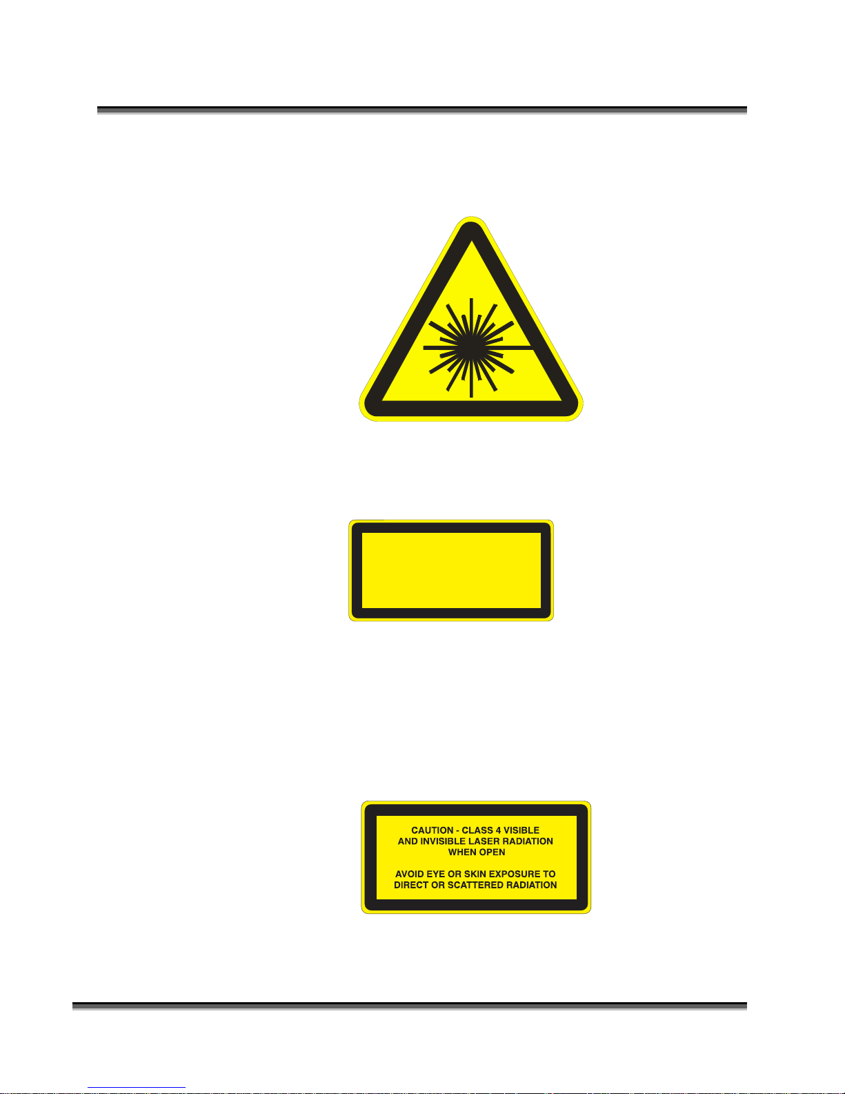
3. Explanatory Label. This label identifies the classification of the Model
13000 in accordance with IEC 60825-1. It is located on the rear of the
machine’s cabinet, beside the Warning Label above.
LASER RADIAT ION
DO NO T STARE INTO BEAM
CLASS 2 LASE R PRODUCT
1 mW CW M AXIMUM 600-700 nm
4. Non-interlocked Protective Housing Safety Labels (4).
Two of these labels are located on the rear of the machine; beside the edges
of each of the cabinet’s end covers. The other two labels are located on the
cabinet walls under the covers, so that they are visible when the covers have
been removed.
6
Page 23
Section 1: Safety
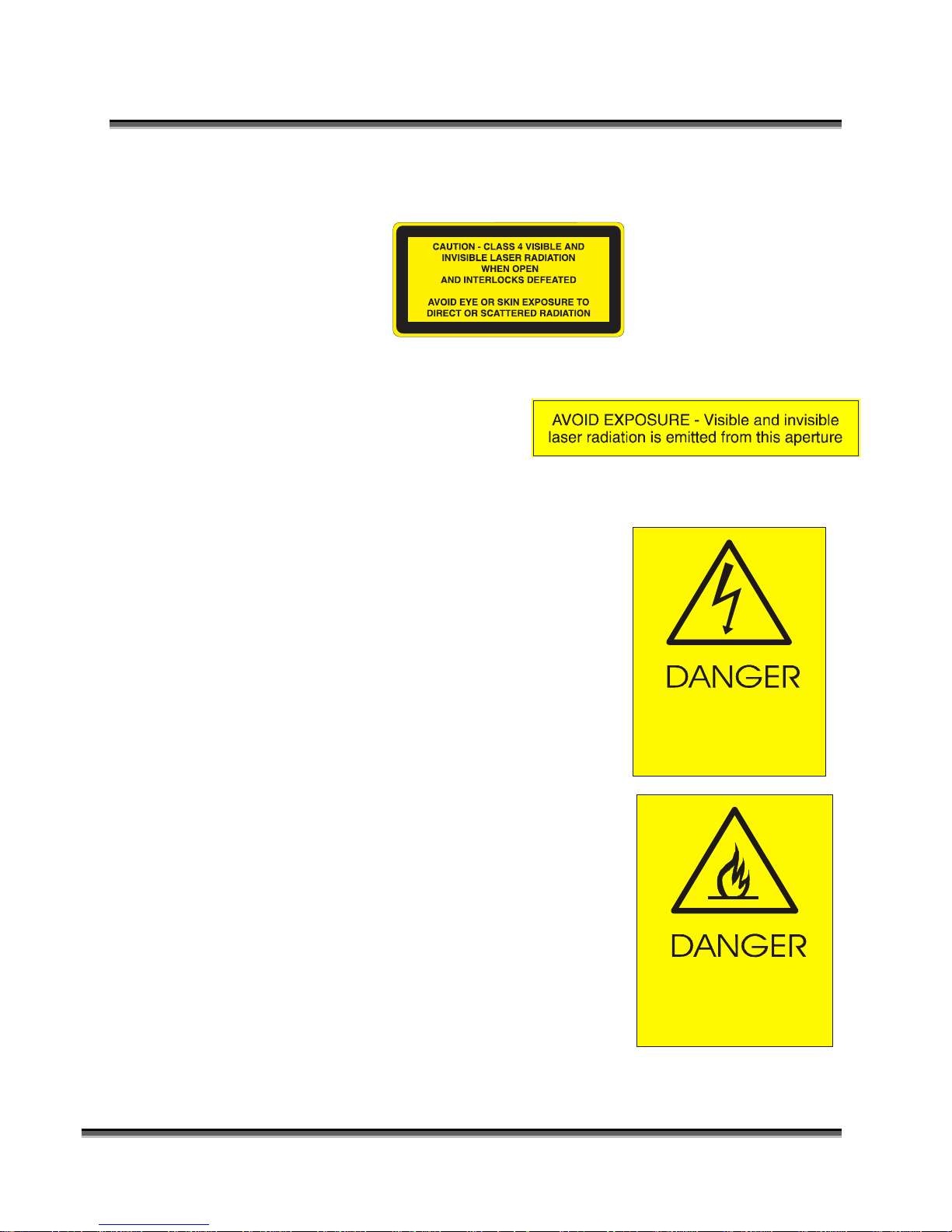
5. Defeatably-interlocked Protective Housing Safety Label. This label is
located on the machine’s cabinet door, in the upper left-hand corner.
6. Aperture Safety Label.
This label is located on the
steering-mirror cover inside the
machine’s cabinet, beside the
aperture where the laser beams enter the cabinet.
7. Electrical Safety Label.
This label is located on the access panel on
the rear of the machine’s cabinet.
HIGH VOLTAGE INSIDE CABINET
DISCONNECT PO WER
BEFORE OPENING PANEL
8. Fire Safety Label.
This label is located on the machine’s cabinet
door, in the upper right-hand corner.
FIRE HAZARD
7
DO NOT OPERATE
MACHINE UNATTENDED
Page 24

Section 1: Safety
9. Emergency Stop
EMERGENCY
STOP
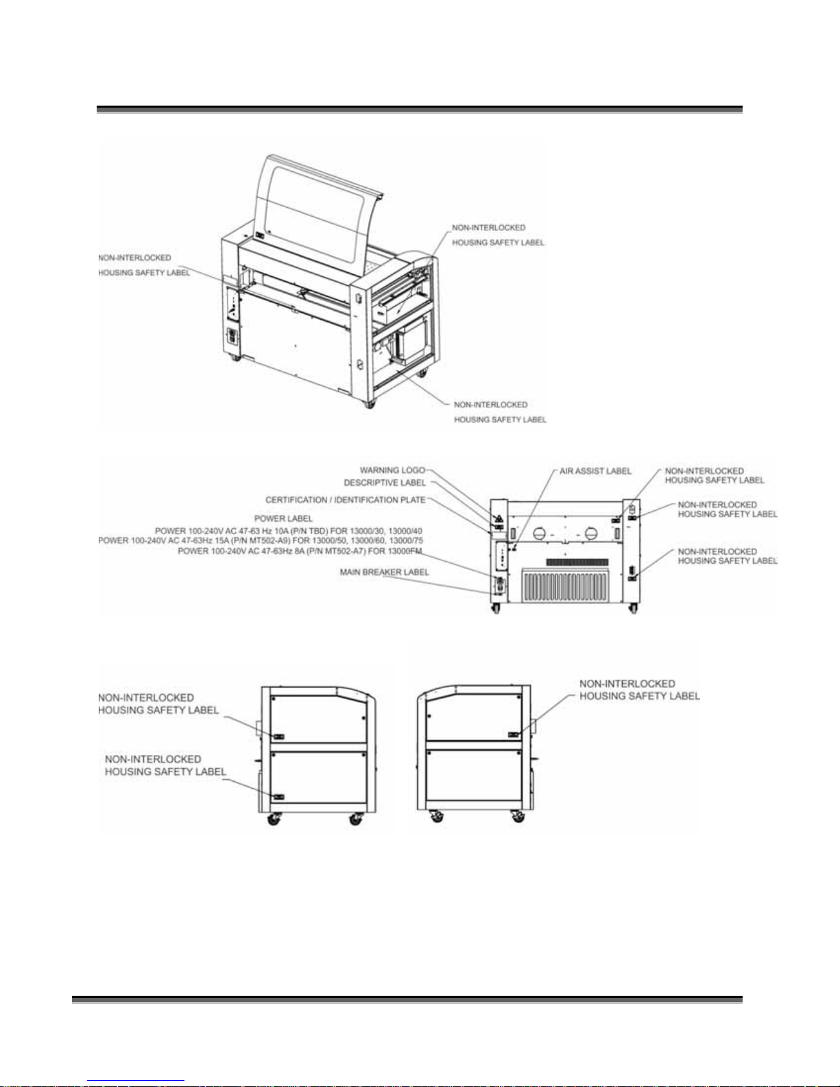
10. Power Labels
11. Main Breaker Labels
12. Air Assist Label
AIR ASSIST
30 PSI MAX
200 kPa MA X
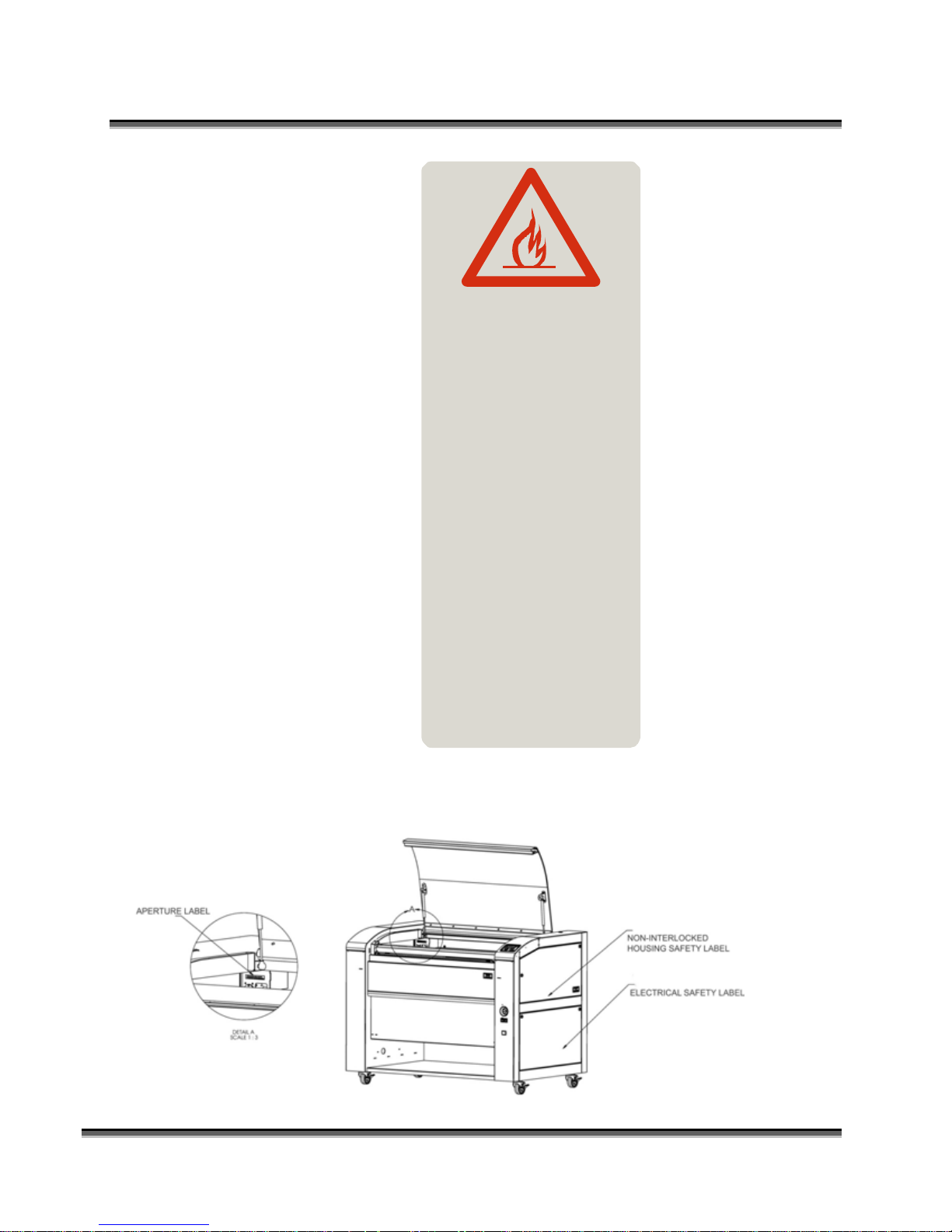
12. Fire Warning Label
This fire hazard label is located on the left and right sides of the top access
door of your laser system:
8
Page 25
Section 1: Safety
DANGER
FIRE HAZARD
DO NOT OPERATE
MACHINE UNATTENDED
USE EXTREME CAUTION WHEN
CUTTING FLAMMABLE MATERIALS
SUCH AS WOOD OR ACRYLI C.
A PROPERLY MAIN TAINED FIRE
EX TINGU ISHER SHOULD BE KEPT
NEAR THE MACHINE AT ALL TIMES.
EPILO G RECOMME NDS A CO FIRE
EXTINGUISHER.
PERIODICALLY REMOVE THE
VECTOR C UTTING GR ID AND
REMOVE DEBRIS FROM THE TABLE
PAN.
PERIODICALLY REMOVE THE
EXH AUST TUBE ADA PTER FRO M
TH E BACK OF THE MACHINE AND
REMO VE ANY DEBRIS FROM THE
EX HAUST PORT.
2
REFER TO THE USERS
MANUAL FO R ADDITIONAL
IN F ORM ATI O N RE GARDI N G
FIRE SAFETY
The following diagrams show the location of each specific label described above.
9
Page 26
Section 1: Safety
10
Page 27

Section 1: Safety
11
Page 28

Section 1: Safety
THIS PAGE WAS
INTENTIONALLY LEFT BLANK
12
Page 29
Section 2: Dos and Don’ts
In This Section
Operating Dos and Don’ts
DON’T!
NEVER operate the machine without a properly operating vent to the outside!
Most material will only produce an irritating smoke when engraved. Some
materials, including but not limited to paint, varnish, composition board and
plastics, produce compounds that can be harmful if concentrated. A properly
installed vent is the only way to ensure that problems do not occur.
NEVER engrave or cut any material containing PVC or vinyl. When engraved, a
corrosive agent is produced that will destroy your machine. Your warranty will
be void if your machine is damaged by corrosion from engraving or cutting
PVC or Vinyl.
NEVER operate your machine unattended. There is a significant risk of fire if the
machine is set improperly, or if the machine should experience a mechanical or
electrical failure while operating.
NEVER vector cut any material while the machine is unattended. Because vector
cutting moves relatively slowly compared to raster engraving, a tremendous
amount of heat is applied to the material being cut. This buildup of heat can
cause significant fire risk and the machine should always be monitored.
Additionally, the air assist should always be turned on when vector cutting to
reduce the risk of fire.
NEVER operate with any of the covers or enclosures removed, and never modify
the enclosure. The laser beam is invisible!
13
Page 30
DO
Section 2: Dos and Don’ts
Please allow a few minutes a week for cleaning your machine. Just a small
amount of effort at the end of the week will pay off with years of trouble free
operation of your machine.
See the Engraving Machine Cleaning section of this manual for specifics.
14
Page 31

Section 3: Getting Started
In This Section
Setting Up Your Laser System
Connecting The Exhaust
Connecting The Electrical Power
Laser Cooling Requirements And Operating Temperatures
Installing the ECC (Epilog Control Panel)
Installing the Dashboard Print Driver
Setting Up Your Laser System
Setting up your Epilog Laser System is easy to do! If you’ve ever installed a
paper printer, this is only slightly more difficult. The following information will
help you understand the entire system and how it works.
Your Fusion laser system consists of the following components:
1) Fusion laser system:
2) Computer and a graphics software package.
1
Page 32

Section 3: Getting Started
3) Epilog software and connection options:
Epilog provides two pieces of software for the Fusion:
1) The ECC (Epilog Control Panel).
2) The Dashboard print driver.
Epilog also provides two different methods of connection the Fusion to your
computer:
1) USB
2) Ethernet
The software and the connection methods are associated because the connection
method affects which software can be used. The following shows how software
and connection methods work:
Connection Method Software Compatibility
USB Dashboard Driver & ECC
Ethernet Dashboard Driver Only
As you can see, the USB provides the most versatility.
The most popular choice is to use the USB for both printing and accessing the
ECC. This choice is the simplest and the most versatile.
One advantage of having two connection options that is not immediately obvious
is that you can use both connections, or just one of them. If you choose, you can
print using the Ethernet connection while using the USB connection for the ECC.
Both the USB and the Ethernet cable can be plugged into the Fusion at the same
time. This method is a little more complicated, but is just as versatile as the USB
only connection.
The last choice is to use only the Ethernet connection. Most users will not choose
this method because the ECC is not available through the Ethernet connection.
2
Page 33

Section 3: Getting Started
4) ECC (Epilog Control Center)
The ECC is the software program that provides job management capabilities to
keep track of print jobs, laser settings and other job management tasks after the
job has been sent to the laser from the Dashboard driver.
The ECC is not required in order to operate your Fusion laser, but is a very
useful job management tool that users find quite valuable.
It is useful to install the ECC prior to installing the print driver.
The ECC ONLY works through the USB
connection. The ECC cannot be accessed
through the Ethernet connection.
3
Page 34

Section 3: Getting Started
5) The Fusion Dashboard print driver.
The print driver is the primary interface between the computer and the laser
and sends all jobs and laser parameters to the laser. Your Fusion laser system
cannot run without the Dashboard driver.
The print driver can be used with either the
USB or Ethernet connection.
Most users will want to install the print driver
on the USB port because they will also want to
use the ECC. The ECC ONLY
works through
the USB connection.
The simplest setup is to install the print driver
using the USB connection. This method allows
you to also use the same USB connection for
the ECC.
4
Page 35

n
Section 3: Getting Started
6) Connection cables that allow your computer and laser to talk to each other.
The Fusion has both Ethernet and USB connections.
7) Exhaust fan. The exhaust fan is mandatory and is used to remove smoke and
debris from the Fusion work area. The exhaust air can be ported to the outside
or into a filter box.
The following drawing represents a typical setup:
5
air flow
exhaust fan
From Fusio
Page 36

Section 3: Getting Started
ETHERNET
USB
Electrical
Connection
(110/220V - 50/60 Hz)
Follow these steps to set up your Fusion laser system:
Remove it from the crate
Connect the exhaust system to your laser
Connect electrical power
Install the ECC (Epilog Control Panel)
Install the Epilog Dashboard Print Driver –
Connect both the USB and Ethernet cables from your computer to your
laser system.
6
Page 37

Section 3: Getting Started
Connecting the Exhaust
It is mandatory that an exhaust blower is installed and operating whenever your
laser system is running a job. The exhaust blower removes the dust, debris and
smell from the engraving cavity and exhausts it to the outside of the building.
You should never operate your laser system without a properly working exhaust.
Prior to the installation of the laser system, a contractor should install the exhaust
system. The blower should be mounted outside your building for noise
considerations. Ideally, the blower should not be more than twenty feet (6
meters) from the laser. You should provide a metal duct (flexible aluminum or
galvanized sheet metal) from the blower to the laser. All Epilog model 13000
laser systems require an exhaust fan that is rated at a minimum of 650 CFM.
Note: Remember to put the blower switch for the laser system in an obvious and
accessible place so it can be routinely switched on prior to using the engraver.
Please connect the exhaust blower to the laser as shown below and on the
following pages.
You may need a contractor to install the exhaust. This must be done PRIOR to
installation of the laser system.
Warning: It’s important that either rigid or flexible metal ducting be used for
all connections leading to and from the laser system and the exhaust fan. Vinyl,
plastic, or any type of “soft” ducting is potentially flammable and should NEVER
be used.
7
Page 38

Section 3: Getting Started
Epilog Exhaust Blower Connections
There are two 4” (100 mm) ports attached to the back of the laser system. Attach your
ducting to the machine as shown above.
Check your exhaust system for leaks. Most small leaks can be remedied with
duct tape.
DO NOT OPERATE your laser with inadequate or leaking exhaust.
The drawings below show the typical exhaust setup. The top drawing shows the
exhaust on the roof and the bottom drawing shows the exhaust fan near the
machine. Where the exhaust fan is placed is a choice of personal preference.
Some users like the exhaust fan outside because of noise considerations.
8
Page 39

Section 3: Getting Started
Exhaust Blower
Connecting Electrical Power
Roof or exterior wall
All Epilog laser systems have an auto-switching power supply that detects the
incoming voltage and automatically switches itself to operate properly at any
single-phase voltage between 100 and 240 VAC. The power supply will also
automatically compensate for either 50 or 60 Hz. Epilog supplies the appropriate
power cord for all of our equipment. The electrical cord is found in the accessory
package with your machine. It is recommended that a dedicated 15 amp circuit be
used if available, but it is not required.
The 60 watt and 75 watt machines draw more current than the lower wattage
lasers. These two systems can operate on 110 volts, but most users find that a 200
V connection is more efficient.
4” (100 mm) flex ible aluminum duct
or rigid galvanized sheet
metal (Do not use vinyl,
plastic or “soft” flexible duct).
The electrical connection is found at the lower back of the machine.
Electrical
Connection
(110/220V - 50/60 Hz)
9
Page 40

Section 3: Getting Started
Laser Cooling Requirements and
Operating Temperatures
All Epilog laser systems use air-cooled laser tubes. Laser technology is such that
the laser tubes generate a lot of excess heat and the tubes must be cooled for
proper operation. There are cooling fans located at the back of the laser. The fans
and vents should always be clear of restrictions and should never be covered.
Warning: The cooling fans and vents are located at the back of the Fusion and
should never be covered or blocked in any way. Lasers that overheat will not
operate properly and may begin to produce erratic laser output or possibly
complete failure.
Ambient air temperature where the laser system is operating should not exceed 90 degrees F (32
C). Operating in an environment where the ambient air temperature is above 90 degrees F (32 C)
will void the Epilog warranty.
10
Page 41

Section 3: Getting Started
THIS PAGE WAS
INTENTIONALLY LEFT BLANK
11
Page 42

Section 4: Installing the ECC
(Epilog Control Center)
In This Section
Installing the ECC
The ECC (Epilog Control Center) provides Job Management features as well as laser control and
laser machine configuration options. The ECC is not required to operate the laser, but it provides
many user features that make operating your Fusion easy.
To install the ECC, insert the Epilog install disk into your computer’s disk drive. It should AutoStart and the following window should appear:
12
Page 43

Section 4: Installing the ECC
If the following screen appears, click on Run fusion_driver.exe and then the
install screen will appear.
Click on Epilog Control Center Installation. You will need to choose between the
32-bit and 64-bit driver based on your computer’s operating system.
13
Page 44

Section 4: Installing the ECC
14
Page 45

Click on Install.
The next screen will prompt you to allow Windows to install the software. Click
Yes.
Select Repair and then Next
Section 4: Installing the ECC
Click on Finish
15
Page 46

Section 4: Installing the ECC
After installing the ECC connect your computer to the laser using either the USB connection or
the Ethernet connection. The following combinations can be used.
USB only connection – Both the print driver and the ECC operate simultaneously through the
USB connection.
Ethernet only connection – The Print driver can be used with the Ethernet connection, but the
Job Management portion of the ECC does not work with the Ethernet connection. However, the
Control tab and the Configuration tab in the ECC are operational and very useful with the
Ethernet connection.
Combination Ethernet and USB – If you choose, you can connect both the USB and Ethernet
connections. This allows you to print through the Ethernet connection and use the ECC through
the USB connection.
16
Page 47

Section 4: Installing the ECC
To install the ECC use the following instructions:
Insert the Epilog install disk into your computer’s disk drive.
USB Port
A USB cable is included in the accessory kit. The USB port is located at the rear
of the machine. USB cables have different connectors on each end. Turn the laser
Off, then connect this end to the laser and connect the other end into any available
USB port at the back of your computer. After connecting the USB cable, turn the
laser back on.
Ethernet Port
The Ethernet Port is a standard 10BaseT connection. A crossover cable (included in the
accessories kit) is used. The Ethernet port is located at the back of the machine. Your
Epilog laser has all of the versatility of a Network capable peripheral. As such, there are
many different ways that the laser can be connected to a computer or a network. A direct
connection using a crossover cable is the only method that will be described in this
manual. Plug the cable into the Ethernet port on the laser and then plug the other end into
the Ethernet port on the back of your computer.
If you are going to print to the Fusion through the Ethernet connection you will want to set the IP
Address in the Fusion using the Configuration tab of the ECC. This part was described in the
previous section of this manual so you do not need to perform this function again if you have
already completed this step. To set the IP Address in the Fusion make sure your Fusion is
powered on then go to your computer and open the ECC to the Configuration tab.
You can also set the IP Address from the Fusion keyboard. Instructions are provided in the
section “Using the Front Control Panel” later in this manual.
17
Page 48

Section 4: Installing the ECC
Type the IP Address you want to
use along with the Subnet Mask.
The Gateway can remain blank.
Click “ Set” to change the setting
in the Fusion.
With the IP Address setting established you are ready to print to the Fusion from the Dashboard
print driver:
The next step is to set up and print a test job:
18
Page 49

Section 4: Installing the ECC
Use Ctrl P, or go to File | Print to print to the laser.
Choose the Fusion driver, and then click on Preferences:
19
Page 50

Section 4: Installing the ECC
Set your laser parameters for the test job and then press Okay. For this test job the laser
parameters are not overly important. We are just making sure the computer and laser are talking
to each other and that a job can be sent and will start running.
20
Page 51

Section 4: Installing the ECC
THIS PAGE WAS
INTENTIONALLY LEFT BLANK
21
Page 52

Section 5: Installing the
Epilog Dashboard Print Driver
In This Section
Installing the Dashboard Print Driver Using an USB Connection
Installing the Dashboard Print Driver Using an Ethernet Connection
The Epilog Dashboard is the print driver that allows your computer to talk to your
Epilog laser system when either the USB or Ethernet Crossover cables are
connected. The driver is included in the accessories kit on a CD-ROM or on our
web site - www.epiloglaser.com. Install the Dashboard by following the
procedures on the following pages.
There are two ways of installing the Epilog Dashboard.
Most users will want to install the driver with using the USB connection.
1. USB connection.
a) The process for Windows XP or Vista is easy and straightforward.
b) The process for Windows 7 or 8 takes additional steps.
2. Ethernet connection.
The Fusion offers both 32-bit and 64-bit drivers. Windows XP, Vista, Windows 7 and Windows
8 can be used.
22
Page 53

Section 5: Installing the Epilog Dashboard
Print Driver
Installing the Dashboard Driver
Using the USB Connection using XP
or Vista
To install the Dashboard print driver using the USB connections with Windows
XP or Vista, follow these instructions:
1. Connect your laser system to your computer using the USB cable that came
with your machine.
2. Power up your Fusion system.
3. Insert the Epilog driver disk into your computer’s hard drive.
4. Your computer will prompt you to install the driver.
5. Follow the prompts.
Installing the Dashboard Driver
Using the USB Connection using
Windows 7 or 8
The process of installing a USB printer when using Windows 7 or 8 is more
complicated than when using XP or Vista. Windows 7 and 8 will not
automatically walk you through the installation process so it is important to
follow the instructions below.
Please follow these instructions closely! Using a
different process to install the Dashboard driver
using a different process is likely to fail if you
are using Windows 7 or 8.
23
Page 54

Section 5: Installing the Epilog Dashboard
Print Driver
1) Insert the Epilog driver install disk into your computer. One of the following
screens will appear. For the USB installation, you will want to close then. We
do not want the computer to automatically try and install the driver. Manually
installing the driver will be much more successful.
2) Connect the USB cable to your computer and your Fusion.
3) After closing the Window above and connecting the USB cable, power on
your Fusion laser system. It will take about a minute for the Fusion to
initialize. After it initializes it will start the process of installing the driver.
You will see activity on the USB icon in your system tray (lower right corner
of your computer screen).
The activity will show a small window in the lower right corner that indicates
installation was successful. This is only partially true.
After a short wait you will see another small window that indicates the
installation was not successful. This is what we hope to see and will lead us to
the next step in the process.
24
Page 55

Section 5: Installing the Epilog Dashboard
Print Driver
If your computer is connected to the Internet, it will take a few minutes for
your computer to display these windows. Please be patient during this process
and let the computer finish trying to install the drivers. Interrupting the
computer at this point will require us to restart the process.
4) After the failure notification, go to the Windows start button (lower left corner
of your computer screen). Click on Devices and Printers.
5) First, right click on the Fusion icon. Then click on Properties.
25
Page 56

Section 5: Installing the Epilog Dashboard
Print Driver
6) Select the Hardware tab.
7) Select the device EpilogEngraverFusion. Then click on Properties.
26
Page 57

Section 5: Installing the Epilog Dashboard
Print Driver
8) Click on Change Settings.
9) Click on the Driver tab.
27
Page 58

Section 5: Installing the Epilog Dashboard
Print Driver
10) Click on Update Driver
28
Page 59

Section 5: Installing the Epilog Dashboard
Print Driver
11) Click on Browse my Computer for driver software
12) Use the Browse button to direct your computer to your disk drive that contains
the Epilog driver disk that you inserted earlier in this process.
For this document we show the DVD RW drive as the drive where the disk is
located.
29
Page 60

Section 5: Installing the Epilog Dashboard
Print Driver
Once you have the proper disk drive showing click on the Next button.
The progress window will appear.
30
Page 61

Section 5: Installing the Epilog Dashboard
Print Driver
13) You will then be asked if you want to install this driver: Click on Install this
Driver Anyway
14) Your Epilog Fusion Dashboard print driver has been successfully installed on
the USB port.
15) Click on Close in the next window and then Close again.
31
Page 62

Section 5: Installing the Epilog Dashboard
Print Driver
You will then see your Fusion driver in the Devices and Printers page. Click
on the red X in the upper right corner of this page.
16) That’s it! You are ready to print to your Fusion.
32
Page 63

Section 5: Installing the Epilog Dashboard
Print Driver
Installing the Dashboard Driver
Using an Ethernet Connection and a
Crossover Cable
If you using an Ethernet connection to print to the Fusion the first steps will show
how to set up your computer to talk to the Fusion before the driver is installed.
The process includes the following steps:
1. Setting the Ethernet IP Address on the laser,
2. Setting up the computer’s TCP/IP Address, and
3. Dashboard Driver Installation.
Note: The following instructions work only for a direct connection from the
computer to the Epilog laser using a Crossover cable. This procedure does not
work with a hub or a server. For Ethernet connections that require a hub, server,
or multiple machines/computers, please consult with your network administrator.
Hardware Requirements
A 10Base-T or 10/100Base T Ethernet network card installed in your
computer. All brand name computers that have been built in the last
couple of years should have come standard with an Ethernet card installed.
A crossover cable connecting your computer to the laser (included in your
accessories kit).
33
Page 64

Section 5: Installing the Epilog Dashboard
Print Driver
Step 1: Setting the Ethernet IP Address on
the Laser
The easiest way to set the IP Address on the Fusion is to first install the ECC and
make the change from the Configuration tab.
You can set the IP Address from the Fusion keyboard on the front of the machine,
however it is more convenient to use the ECC. See the section on “Using the
Front Control Panel” for keyboard instructions.
Type the IP Address you want to
use – we have used 192.168.3.4.
Type in the Subnet Mask of
255.255.255.000. The Gateway
can remain blank.
Clicking “ Set” will enable these
setting in the Fusion electronics.
34
Page 65

Section 5: Installing the Epilog Dashboard
Print Driver
Step 2: Setting up the Computer’s TCP/IP Address
Once you have set the IP Address on the laser you will need to set the TCP/IP
Address in your computer.
1. From the Start menu at the bottom of your computer monitor screen select
Start | Control Panel | Network Connections.
2. There are additional instructions for different Windows versions in the
Appendix at the back of this manual if your Windows version is different
than the one shown below.
Right mouse click on the
Local Area Connections
icon, then click on
Properties.
3. Highlight the Internet Protocol
(TCP/IP) V4.
4. Then click on Properties.
35
Page 66

Section 5: Installing the Epilog Dashboard
Print Driver
5. The window below will appear. Select Use the following IP address radio
button.
6. Type in the following (leave everything else blank on this page).
IP Address 192 168 3 3
Subnet Mask 255 255 255 0
Default Gateway Leave blank
7. Click the OK button in this window and then click on the Close button in
the next window.
8. Your computer is now set to print through a crossover cable to the Ethernet
port on the laser.
36
This number is not an error -the last digit of the IP address
in this window must be
different than the IP address
set in the Fusion.
Page 67

Section 5: Installing the Epilog Dashboard
Print Driver
Step 3: Installing the Dashboard Driver for an
Ethernet Connection
Insert the Epilog Laser CD into your computer’s disk device. It should Auto-Start
and the following window should appear:
If the following screen appears, click on Run fusion_driver.exe and then the
install screen will appear.
:
Click on Dashboard Driver Install.
37
Page 68

Section 5: Installing the Epilog Dashboard
Print Driver
Click on Add Local Printer:
38
Page 69

Section 5: Installing the Epilog Dashboard
Print Driver
Click on Create New Port and then click on the dropdown menu and select
Standard TCP/IP Port
Enter the IP Address you want to use. Most Epilog users will use 192.168.3.4 that
is what we use in this document. Whatever number you use, it must be the same
number you assigned to the IP Address in the Fusion laser.
After typing in the IP Address, click on Next.
39
Page 70

Section 5: Installing the Epilog Dashboard
Print Driver
Wait while the computer identifies the port.
Select Custom and then Settings, then click on Next
40
Page 71

Section 5: Installing the Epilog Dashboard
Print Driver
Select LPR and type in Laser into the Queue Name. Then, Click on OK.
Set Protocol to
LPR. This is a very
important step.
Your download
time will be greatly
increased if LPR is
not selected.
After clicking OK above you will return to the window below. Click on Next.
41
Page 72

Section 5: Installing the Epilog Dashboard
Print Driver
Click on Have Disk
Click on Browse
Find the disk drive with the Epilog install disk and click on Open
Select the driver folder and then click on Open
42
Page 73

Section 5: Installing the Epilog Dashboard
Print Driver
Click on the EpilogWinALLFusion file and then click on Open
43
Page 74

Section 5: Installing the Epilog Dashboard
Print Driver
Click on OK
Click on Next
You can rename your printer here. We have not changed it for this document. We have not
changed it for this document, but many users like to associate the driver name with the IP
Address they are using. Especially if there is more than one laser connected to a single computer.
Click on Next.
44
Page 75

Section 5: Installing the Epilog Dashboard
Print Driver
Click on Finish and the driver has been installed! You are ready to print.
45
Page 76

Section 5: Installing the Epilog Dashboard
Print Driver
THIS PAGE WAS
INTENTIONALLY LEFT BLANK
46
Page 77

Section 6: Using the Epilog
Dashboard
In This Section
General Tab
Advanced Tab
Color Mapping Tab
Additional Dashboard Features
Changing Dashboard Defaults
The Epilog Dashboard is the print driver that sends your artwork and laser
parameters from the computer to the laser.
The Dashboard is shown below and can be installed from the driver CD that came
in your accessories kit. It can also be downloaded from the Epilog web site –
www.epiloglaser.com. If you are just getting started and are in a hurry to engrave
a job, you can do so by setting just a couple of parameters in the Dashboard
without having a detailed understanding of what different choices are available to
you.
To get started with a simple engraving job, type your name in CorelDraw, press
the Ctrl and P keys to print, select the Dashboard as the Destination to your
printer and go into Properties. Set the following parameters:
47
Page 78

Section 6: Using the Epilog Dashboard
Now that you have printed a simple job, you are ready to gain a better
understanding of the different printing options available from the Dashboard.
Most engraving and cutting jobs can be accomplished by using only the General
tab. Advanced features for more complex jobs can be found under the Advanced
and Color Mapping tabs.
Note! – When using the slider bars, there are several different ways to get the
desired setting. These different methods all follow standard Windows protocol,
so they will work in other Windows software applications too.
You can move the settings in increments of one by using the + and – icons.
You can move the slider in increments of ten by clicking close to, but not on,
the slider. Holding down the Alt key on your computer keyboard while
clicking close to the slider will bring up the dotted box outlining the slider and
will allow a little better control of moving in increments of ten. Clicking
directly on the slider control (the little box in the center) will also bring up the
dashed outline.
48
Page 79

Section 6: Using the Epilog Dashboard
You can move the little slider box by clicking down, holding and then moving
to the desired number before releasing your mouse.
You can type the setting into the number box.
The following sections provide detailed explanations of the different features in
the Print Driver. Most engraving and cutting jobs can be accomplished by using
only the General tab of the Print Driver. Advanced features for more complex
jobs can be found under the Advanced tab.
NOTE: The Fusion driver is used for both CO2 laser and the Fiber laser sources.
There are a few functions in the driver that only apply to one laser type or the
other. Most functions apply to both, but if a function does not apply to the laser
type installed in your machine that function will be “grayed out”. For instance, in
the image below we have selected Laser Type as CO2. Notice that the Freq
function under Raster Setting is Grayed out. This setting is only used with the
Fiber laser so it is not necessary to try and set it with the CO2 laser.
49
Page 80

Section 6: Using the Epilog Dashboard
General Tab
Job Type
One of the first things new users want to know is how the laser system knows
when to engrave and when to cut. The decision is based on several variables:
1) Line weight (or Stroke) as defined in your graphic image from Corel,
Illustrator, etc. The line weight of your object will determine if it will
engrave or cut.
2) The Resolution as set in the DashBoard driver will also have an effect
on which lines will engrave and which will cut.
3) The Job Type as set in the DashBoard driver - Raster, Vector or
Combined.
To make things easy on themselves, most users set their lines for vector
processing as a Hairline (0.003”) and make the lines red. This provides
a very clear indicator that there is a vector line in the artwork.
Raster Mode – This mode will only engrave. Vector lines will not be processed
from this mode.
Vector Mode – This mode will only vector. Raster images will not be processed
from this mode.
Combined Mode – By properly setting up your artwork you can both engrave
and cut from this mode.
50
Page 81

Section 6: Using the Epilog Dashboard
Select the Job Type
here.
Raster
Raster mode is used for marking or engraving materials. Typical uses would be
reproducing clipart, scanned images, photos, text and graphic images. The Raster
Speed and Raster Power boxes will be enabled when you have selected Raster
under Job Type. Set the Speed and Power boxes to the appropriate settings for
the material that you are engraving. For speed and power guidelines, see the
Speed and Power Recommendations section of this manual.
Note – Very thin lines will not raster engrave, and the definition of “thin” varies
depending on the Resolution being used. Most users use a Hairline or 0.003” line
to designate vector lines.
Example: The rectangle below has a line weight of 0.003 inch. It will not raster
engrave at any resolution. If you send just this box to the laser in Raster mode
and try to run the job, the laser will beep once and be finished because the line is
too small to be recognized as an engraving line.
Line weight = 0.003 inch.
51
Page 82

Section 6: Using the Epilog Dashboard
Vector
Vector mode is used for thin line marking as well as cutting applications. The
Vector Speed, Power and Frequency bars will be enabled when you have selected
Vector or Combined under Job Type.
Note - Artwork, such as scanned images, photos, JPEGs, etc. will not vector cut
because they do not contain thin lines of any kind.
Note: When you are cutting in Vector or Combined mode be aware that your best
results are typically produced at slower speeds. The highest speeds are
specifically designed for draft mode or less demanding applications where speed
is much more important than quality.
Note – Very thin lines are used to define Vector cutting and the definition of
“thin” varies depending on the Resolution being used. As a general rule, most
users set their vector line weights to Hairline or 0.003 inch.
Example: The rectangle below has a line weight of 0.003 inch. It will vector at
any resolution.
Line weight = 0.003 inch.
52
Page 83

Section 6: Using the Epilog Dashboard
When using vector mode, it is necessary to design your job to give the intended
result. Objects and text should be unfilled and drawn with the thinnest possible
outline (other than zero), as shown below. A .001 inch (.025 mm) is
recommended.
CORRECT Vector setup INCORRECT Vector setup
Combined
Combined mode is used when you want to incorporate both Raster and Vector
functions in the same job setup. When you are in Combined mode, all Raster
operations will be performed first, with the Vector operations second.
Note on Vectors: If you are in Vector or Combined mode, all thin lines will be
vector cut! This can be disconcerting because even if the lines are not visible in
your artwork they will still cut. Usually, this happens when incorporating a
clipart image that has hidden lines that are not readily apparent. Please refer to
the Quick Start & Easy Setup section of this manual for an illustrated explanation
of how this can affect your work.
In addition to speed, power and frequency, there are two additional parameters for
vector mode:
Slow Cutting:
Slow Cutting reduces all speed settings by ½. For example, a speed setting of 10
without Slow Cutting select will move twice as fast as a setting of 10 with Slow
Cutting selected. In essence, Slow Cutting provides an alternative set of speed
parameters that are ½ the speed as the standard settings. Slow Cutting mode will
most often be used for very slow cutting applications when the standard settings
are too fast. Most users will rarely use Slow Cutting mode, but it adds an
additional mode of operation for unusual or demanding applications.
53
Page 84

Section 6: Using the Epilog Dashboard
Power Comp:
Power Comp (Compensation) adds another dimension to Vector Cutting
settings. Selecting Power Comp is especially useful for vector cutting jobs that
incorporate a large number of curves. Power Comp slows the lens carriage and
automatically reduces the laser power to compensate for the change of speed as
the carriage moves through a curve. This has the effect of producing unparalleled
edge quality when cutting curves. Straight lines are cut more quickly and
efficiently with Power Comp deselected, but many users find that while selecting
Power Comp may sacrifice a little speed for straight line cutting, the better edge
quality in curves is worth it. For most applications, we suggest selecting Power
Comp.
Resolution
Print quality is commonly referred to as Resolution, and is one of the variables
that determine image quality. Resolution is expressed in dots-per-inch (DPI) and
is determined by the number of lines or dots that are engraved for every inch of
movement. Each horizontal line is referred to as a raster line. The higher the
resolution setting, the finer the detail that can be achieved. Keep in mind that
engraving resolution is only one factor in determining image quality. The quality
of the artwork being sent to the laser can have a bigger influence on the look of
the final product than the resolution. If low quality artwork is being used, even
the highest resolution will not improve it. Also keep in mind that image quality is
subjective. 300 DPI may be just fine for some images and some customers, while
600 DPI is the absolute minimum for others.
54
Resolution (Print
Quality) is set in the
Dashboard prior to
sending the job to the
laser.
Higher resolution
produces better image
quality.
Page 85

Section 6: Using the Epilog Dashboard
Speed and Power settings are dependent on resolution setting. For example, there
is greater overlap of each raster line at 600 DPI than there is at 300 DPI. The
additional overlap at 600 DPI has the effect of lasering over more of each line
twice. This means that on material like wood, you will notice a greater depth of
engraving at 600 DPI than you will at 300 DPI if you use the same Speed and
Power settings.
Resolution Settings
Uses for different resolution settings:
75 – 150 DPI
These resolution values are typically used for non-production purposes where you
want to experiment with image location, or if you want to quickly produce a
rough draft.
200 DPI
Some users like 200 DPI for engraving photographs that have been processed
through PhotoGrav or other photo editing software designed for the laser. Other
users prefer 300 DPI for this style of photographs.
300 DPI
This resolution can be good for production work where image quality needs to be
good, but not great. Many users will use 300 DPI on plastic and other materials
that don’t require a lot of power in combination with large block lettering.
Attempting to produce really fine detail with 300 DPI is not recommended.
400 DPI
This resolution value is ideal for many applications. It combines very good image
quality with fast engraving times. Many users like 400 DPI for all of their work.
600 DPI
When really fine detail or overall excellent results are required, most users choose
600 DPI.
1200 DPI
This resolution is used for projects that require the best engraving quality
possible, although it’s seldom used because under normal circumstances most
people cannot visually discern the difference between 1200 and 600 DPI. There
55
Page 86

Section 6: Using the Epilog Dashboard
are however some users that appreciate this high level of quality and are willing to
take twice as long to produce an image at 1200 DPI as it would take them at 600
DPI.
The diagram below shows the concept of raster lines and dots-per-inch (DPI).
The arrows show the change in direction of the carriage between raster lines. The
difference in dot density between 300 DPI and 600 DPI resolution is shown.
600 DPI300 DPI
Helpful Hints
1. There are four times as many dots engraved at 600 DPI than there are at 300
DPI - twice as many horizontally and twice as many vertically.
2. The gap between the dots is very small at 600 DPI. At 300 DPI the lesser
overlap is responsible for the jagged edges that are visible when engraving
at lower resolutions. It’s important to remember that while resolution plays
a part in producing good image quality, the artwork that is sent to be
engraved is just as important. If the artwork that is sent to the laser is poor
quality, trying to engrave it at 600 DPI will not improve it. It’s always best
to start with high resolution images. Poor artwork will probably always
look poor at any resolution, while good artwork will look good at any
resolution.
3. Twice as many dots and twice as many lines at 600 DPI produces a much
deeper burn into materials like wood than you would see engraving the
same thing at 300 DPI. This is important to understand because depth of
burn is closely associated with engraving resolution – the higher the
resolution, the greater the depth of burn for a given speed. The relationship
between resolution, depth of engraving and Speed and Power setting is
something that most people figure out with just a little experience. The
Speed and Power Recommendations section of this manual helps to make
this easy to understand by providing different Speed and Power settings for
300, 400, and 600 DPI engraving for each different material listed.
56
Page 87

Section 6: Using the Epilog Dashboard
The photos below show a CorelDraw clipart image engraved at 300 DPI (top) and
at 600 DPI (bottom). This clipart image is full of different shades of gray and
you can see that the dot spacing is spread out more on the 300 DPI than it is on
the 600 DPI. Just changing the resolution to 600 DPI produces so much dot
overlap that the fill patterns tend to blend together. It’s a matter of personal
preference as to which resolution looks better, but these photos show the dramatic
difference resolution can make, especially when engraving with grayscale images.
300 DPI
600 DPI
57
Page 88

Section 6: Using the Epilog Dashboard
Piece Size
Many users like to create their artwork on a page size in CorelDraw or other
software program that matches the size of the piece that is to be lasered.
Compensating for beveled edges or placing an image in an exact location is easy
when there is a one-for-one relationship between the material and the page size of
the artwork. If this method works for you, set the Piece Size dimensions to match
the page size you have set in your graphics software.
On the other hand, many users do not want to change the Piece Size dimensions
every time they print something new. They prefer to use a standard page size in
Corel that matches the table size (32” x 20” for example) and place their artwork
into the upper left corner of the page prior to printing.
Both methods are effective and it is a matter of personal preference which method
is used.
58
Set the Piece Size in the
driver to match the page size
from your Corel file.
Page 89

Section 6: Using the Epilog Dashboard
Auto Focus
Most users prefer to use the Auto Focus capability when focusing because it is so quick
and easy to use.
To use auto focus first measure the thickness of the material you are using. Click on Auto
Focus and the input the material thickness using decimal units into the Thickness box.
The table will move up or down so that the top of your material is 2” below the bottom of
the focus lens.
If there the Auto Focus box is not selected, Auto focus will be disabled and the
table will not move up or down when the job starts.
When the Vector Grid is installed and you want to use Auto Focus, click both the
Auto Focus box and the Vector Grid box. This tells the laser system that the
vector grid is installed and it will automatically calculate the appropriate focal
distance based on this information. Please note – The material thickness is still
required when using the vector grid. If a thickness is not specified the system will
auto focus to the top of the vector grid, not to the top of your material.
Use a pair of calipers for an accurate measurement of your material thickness and
enter this value in the “Thickness” box in the driver.
WARNING: If you are using Auto Focus and you know there is not enough
clearance between the lens carriage and your material, you will need to lower the
table before you insert your material and start the job. To lower the table, use the
59
Page 90

Section 6: Using the Epilog Dashboard
Note: Please be careful when auto focusing on irregularly shaped items. The
crash bar and air assist tube must clear all edges of the work piece in this
situation also.
Crash bar
60
Page 91

Section 6: Using the Epilog Dashboard
Engrave Direction
This feature applies to Raster engraving only and allows you to engrave your
project either from the top down, or the bottom up. This is very helpful for some
materials like plastic or rubber stamps. In standard top-down engraving there can
be a large amount of engraving debris generated. As the debris moves towards
the exhaust plenum, some of it collects in the area that has just been engraved.
Bottom-Up engraving prevents the debris from collecting in the freshly engraved
spaces.
Top-down engraving starts from the
top and works its way down.
Bottom-Up engraving starts from the
bottom and works its way up.
61
Page 92

Section 6: Using the Epilog Dashboard
Raster Settings
Speed
The Speed setting determines the travel speed of the carriage in Raster mode and
is adjustable in 1% increments from 1 to 100%. The slower the speed, the deeper
the engraving. Speed settings are heavily dependent on the hardness and the
thickness of the material being engraved, with harder materials requiring slower
speeds for deeper engraving. Slower speed settings will produce greater depth of
engraving. Please refer to the Speed & Power Recommendations section of this
manual.
An important note: Speed and Power settings can sometimes be confusing
because not all materials that can be marked at the highest speeds and powers
should be marked at the highest speed or power. Many users feel that if a mark
can be made at high speed, it’s just a matter of adjusting the power to produce an
acceptable mark. Usually, this is the case, but unfortunately, for some difficult
materials it doesn’t always work. For some materials, the length of time the laser
reacts with the material is much more important to producing a good mark than
the raw speed of the system or the amount of laser power that is output by the
laser.
The interaction of the laser with different materials is a complex process, and this
is especially true for some materials that are actually two different materials that
have been bonded together. Since the laser interacts differently with each layer of
62
Page 93

Section 6: Using the Epilog Dashboard
material (and sometimes even the bonding agent), you may be better off slowing
the machine down to give the laser time to properly interact with the different
layers in the material.
If you have a multi-layered material that you can mark easily, but not well, at high
speeds, try lowering the speed to see if that produces a better mark. If you’re able
to produce a better mark, but it’s overpowered, lower the power also.
Power
The Power setting determines the amount of laser energy that is delivered to the
piece being cut and is adjustable in 1% increments from 1 to 100%. The higher
the power, the deeper the engraving. Please refer to the Speed & Power
Recommendations section of this manual.
Dithering
Dithering defines how the dot patterns will be engraved in raster images that
contain grayscales, blends, or color. The Dashboard offers six different dithering
patterns to enhance your engraving projects. The default mode is Standard. This
mode can be used for all images including photographs. Dithering is used only
for Raster engraving and has no effect on vector cut lines.
The dropdown list of dithering patterns is easier to think about if you separate the
six options into two categories that we will refer to as Clipart and Photograph:
63
Page 94

Section 6: Using the Epilog Dashboard
Clipart Modes – Standard, Brighten and Low Res modes are typically used for
clipart images or anything that has been created using a software application like
Corel. Standard mode is the default mode and is by far the most commonly used.
It produces a very structured pattern to the dot patterns being engraved. Brighten
and Low Res decrease the number of dots in the engraving pattern and can be
used effectively to remove the washed out appearance of some images (including
photographs).
Photograph Modes – Floyd Steinberg, Jarvis and Stucki modes are designed to
modify an image by replacing the very structured dot patterns with a more
random dot pattern. Engraving in one of these modes can make a photograph
engraved on marble or anodized aluminum look more appealing than using an
unmodified image. These modes can also be used for special effects of clipart
images.
Experiment with the different dithering patterns to determine which effect is most
pleasing. It is not mandatory that you use the clipart modes with only clipart
images or photograph modes with all photographs. Many users prefer one of the
photograph modes for many clipart images, and one of the clipart modes for
photographs. The choice is entirely up to you!
We have included some sample photographs on the Epilog driver disk for you to
experiment with. Use these photographs to engrave on different materials using
the different dithering options so you can get a feel for how each dithering pattern
affects the image and the material.
Laser engraved photographs on wood usually require a third party software
package to produce a good image that is suitable for the laser. Epilog
recommended PhotoLaser Plus for this application. Users find it an invaluable
piece of software that is easy to use and will produce much better looking images
when working with wood.
64
Page 95

Section 6: Using the Epilog Dashboard
What is Dithering? - The best way to show dithering is with an example. In the example below,
we engraved the exact same photo in Standard mode and Stucki mode. Both photos were
engraved at 300 DPI. As you can see, the photos look dramatically different. As you can also
see, the Standard mode shows a very structured pattern, while the Stucki pattern shows a much
more random pattern that is much more pleasing to the eye.
300 DPI using Standard mode 300 DPI using Stucki mode
300 DPI using Standard mode
300 DPI using Stucki mode
65
Page 96

Section 6: Using the Epilog Dashboard
Clipart Modes:
Standard - This mode is the default mode and will be used for most engraving
jobs that include text and clipart at 600 DPI.
Brighten – Many users find this mode good for engraving photographs onto
wood or marble at 600 DPI.
Low Res - Adds an artistic half-tone type look to the engraving.
Photograph Modes:
Floyd-Steinberg – Produces an almost wave-like pattern to an image. This
works well for some photos containing a great deal of detail. Photos with more
monotone swatches of color may not be as pleasing as Jarvis or Stucki modes.
Jarvis – Many users find this mode good for engraving photographs at 300 DPI.
This mode produces a very nice looking pattern on almost all photos.
Stucki - This mode produces results that are only marginally different than the
Jarvis dithering pattern. It is also very good for engraving photographs at 300
DPI. The differences between Jarvis and Stucki are very subtle.
Dithering is a great way to enhance your engraved products, but it can be
frustrating sometimes because the look that is achieved will be different from one
material to the next. A graphic image that looks good on wood may not look as
good on plastic. Give yourself some time to experiment with the different
dithering patterns. It’s easy to do and once you have a feel for it, you will be able
to use it with confidence!
66
Page 97

Section 6: Using the Epilog Dashboard
Vector Settings
Speed
The Speed setting determines the travel speed of the carriage in Vector cutting
mode and is adjustable in 1% increments from 1 to 100%. The slower the speed,
the deeper the cut. Most cutting applications require relatively slow speed
settings, and the speed is heavily dependent on the hardness and the thickness of
the material being cut. Slower speed settings will also produce better edge
quality. Please refer to the Speed & Power Recommendations section of this
manual. High speeds are provided for draft mode only and are not intended for
production applications.
Power
The Power setting determines the amount of laser energy that is delivered to the
piece being cut and is adjustable in 1% increments from 1 to 100%. The higher
the power, the deeper the cut. The amount of power necessary to cut completely
through a given material is also heavily dependent on the hardness and the
thickness of the material. Please refer to the Speed & Power Recommendations
section of this manual.
67
Page 98

Section 6: Using the Epilog Dashboard
Freq (Frequency)
Frequency is the number of laser pulses that the laser fires per inch of travel and is
set in the dashboard and can be adjusted from 1 to 100. A lower frequency
number will have the effect of less heat because fewer pulses are being used to cut
the material. Lower frequency rates are helpful for products like wood where
charring is evident at higher frequencies. High frequencies are useful on material
like acrylic where a large amount of heat is desirable to melt, or flame polish the
edges.
Very low frequencies, (from about 1 to 5) will produce a perforation, as opposed
to a continuous cut.
Low Frequency Pulsing
Higher Frequency Pulsing
68
Page 99

Section 6: Using the Epilog Dashboard
Vector Sorting
A checkmark in the vector sorting box will order the sequence of vector cuts. If
sorting is enabled, you have two choices of how the vector lines will be sorted:
Optimize and Inside-Out. In Optimize mode, vectors will be cut in the most
efficient manner, and will generally vector the next closest line to the one just
finished. This is by far the most preferred method as it saves the most time, is the
most predictable and will create a continuous line path out lines that look
connected, but are actually discrete line segments in the artwork. The continuous
path of discrete lines is most often found in AutoCAD or other CAD programs.
Inside-Out mode will vector from the inside object first to the outside objects last.
As an example, if you have a small circle surrounded by a large circle, the small
circle will cut first. If sorting is not checked, the vectors will cut in the order in
which they are presented, which with most software applications will mean in the
order they were drawn.
69
Page 100

Section 6: Using the Epilog Dashboard
Configurations
The “Configurations” feature is a comprehensive data management tool that is
used to save all of your Dashboard settings for individual jobs. Saving the
Dashboard settings as a database file allows you to retrieve the job parameters at a
later time. This saves you the trouble of trying to remember what speed and
power and other settings you used on a job you did three months ago. All of your
settings can all be stored as a permanent record.
70
 Loading...