

Page 1
FUSION M2 32 / 40
LASER SYSTEM MANUAL | MODEL 13000 / 14000
Register your system now for driver update notifications
and FREE files! EPILOGLASER.COM/REGISTER
Technical Support: +1 (303) 215-9171
Knowledge Base: support.epiloglaser.com
System Registration: epiloglaser.com/register
Driver/Firmware: epiloglaser.com/fusion-drivers
UPDATED MAY 2018 | EPILOGLASER.COM/MANUALS
Page 2

Page 3

TABLE OF CONTENTS
Fire Warning 1
Introduction 2
How to Use This Owner’s Manual ..............................................................................................................................................2
Icons Used in this Manual .........................................................................................................................................................2
Section 1: Safety 3
Laser Safety ..............................................................................................................................................................................3
Electrical Safety .........................................................................................................................................................................4
Fire Warning ..............................................................................................................................................................................5
Safety Features and Regulatory Compliance .............................................................................................................................6
Do’s and Don’ts .......................................................................................................................................................................10
Section 2: Getting Started 11
1. Unpacking the Laser System ...............................................................................................................................................11
2. Choose Where to Locate the System...................................................................................................................................12
3. Connecting the Exhaust .......................................................................................................................................................13
4. Connecting Electrical Power ................................................................................................................................................15
5. Setting Vector Cutting Table Default ....................................................................................................................................15
6. Connect the Laser to Your Computer ..................................................................................................................................15
7. Set the Fusion’s IP Address .................................................................................................................................................16
9. Sign Up for Driver Updates and Register Your System .......................................................................................................18
Section 3: Driver Installation 19
Windows 7: Ethernet Installation .............................................................................................................................................19
Windows 7: USB Installation ...................................................................................................................................................22
Windows 8 and 10: Ethernet Installation .................................................................................................................................25
Windows 8 and 10: USB Installation .......................................................................................................................................28
Setting Up CorelDRAW Beziers Setting ...................................................................................................................................31
Mac Driver Installation ............................................................................................................................................................32
Section 4: The Epilog Job Manager 37
Epilog Job Manager Instructions.............................................................................................................................................37
How to Install the Epilog Job Manager ....................................................................................................................................37
Trouble Shooting Job Manager Installation .............................................................................................................................39
Important Epilog Job Manager Notes ......................................................................................................................................40
Using the Epilog Job Manager ................................................................................................................................................40
Section 5: Using The Laser Dashboard™ 49
Changing Laser Dashboard Defaults .......................................................................................................................................49
General Tab .............................................................................................................................................................................50
Advanced Tab ..........................................................................................................................................................................54
Color Mapping Tab ..................................................................................................................................................................56
Additional CorelDRAW Laser Dashboard Features ..................................................................................................................57
Section 6: Using The Epilog Mac Driver 59
Mac Driver Settings .................................................................................................................................................................59
Project Setup...........................................................................................................................................................................62
Vector Cutting Lines ................................................................................................................................................................63
Section 7: Fusion Control Panel 65
Display ....................................................................................................................................................................................65
- i -
Page 4

TABLE OF CONTENTS
Joystick ...................................................................................................................................................................................74
Job Storage: Temporary Memory ............................................................................................................................................75
Section 8: Quick Start Guide 77
Artwork Setup .........................................................................................................................................................................77
Setting a Vector Cutting Line ...................................................................................................................................................78
Resolution ...............................................................................................................................................................................79
Piece and Page Size ................................................................................................................................................................83
Section 9: Cleaning & Maintenance 85
Reduce Fire Risk with a Clean Laser ........................................................................................................................................85
Cleaning the Optics .................................................................................................................................................................85
Cleaning and Lubricating the Bearing Rails .............................................................................................................................87
Cleaning the Exhaust Plenum ..................................................................................................................................................88
Laser Tube ...............................................................................................................................................................................91
Laser Tube Air Filter ................................................................................................................................................................91
Section 10: System Features 93
Air Assist .................................................................................................................................................................................93
Auto Focus vs. Manual Focus ..................................................................................................................................................93
Crash Bar ................................................................................................................................................................................95
Image Dithering.......................................................................................................................................................................96
Color Mapping.........................................................................................................................................................................97
Reset Home Position .............................................................................................................................................................104
Red Dot Pointer .....................................................................................................................................................................104
Movable Home Position ........................................................................................................................................................105
Center Engraving ...................................................................................................................................................................106
Emergency Stop Button ........................................................................................................................................................108
Front Access Door .................................................................................................................................................................109
Task Plate/Vacuum Hold-Down Table ....................................................................................................................................109
Exhaust Plenum ....................................................................................................................................................................110
Safety Interlock / Laser Status Indicators ..............................................................................................................................111
Rulers..........................................................................................................................................................................................
Section 11: Optional Features 113
Vector Cutting Table/Vacuum Hold-Down Table ....................................................................................................................113
Pin Table ...............................................................................................................................................................................114
Fusion Rim-Drive Rotary Attachment ....................................................................................................................................117
3-Jaw Chuck Rotary Attachment ..........................................................................................................................................125
eView Camera Module ...........................................................................................................................................................135
Dual Source Option ...............................................................................................................................................................146
PhotoLaser Plus ....................................................................................................................................................................148
Section 12: Upgrading the Operational Firmware 155
How to Upgrade Your Firmware ............................................................................................................................................155
Section 13: Printing From AutoCAD 159
How to Print from AutoCAD to the Laser...............................................................................................................................159
Section 14: Material Engraving Techniques 161
CO2 Laser Materials/Techniques ..........................................................................................................................................161
3D Engraving .....................................................................................................................................................................161
- ii -
Page 5

TABLE OF CONTENTS
Acrylic ...............................................................................................................................................................................162
Anodized Aluminum ..........................................................................................................................................................163
Brass - Painted ..................................................................................................................................................................164
Glass .................................................................................................................................................................................165
Notary Seals: Delrin ...........................................................................................................................................................166
Plastic Engraving/Cutting ..................................................................................................................................................167
Rubber Stamps ..................................................................................................................................................................168
Wood .................................................................................................................................................................................172
Fiber Laser Materials/Techniques ..........................................................................................................................................175
Metal Annealing .................................................................................................................................................................175
Metal Etching ....................................................................................................................................................................175
Metal Polishing ..................................................................................................................................................................176
Plastic Marking .................................................................................................................................................................176
Section 15: Specifications 179
Fusion Laser Technical Specifications ...................................................................................................................................179
Compatibility .........................................................................................................................................................................180
Recommended PC.................................................................................................................................................................180
About The CO2 Laser Source ................................................................................................................................................181
About the Fiber Laser Source ................................................................................................................................................182
Federal Communications Commission (FCC) Notice .............................................................................................................182
Section 16: Technical Support 183
Contacting Technical Support ................................................................................................................................................183
Frequently Asked Questions .................................................................................................................................................184
Section 17: Material Suppliers 187
Industry Material Supplier List ..............................................................................................................................................187
Appendix A: Warranty Statement 191
Warranty Statement for the Fusion Laser ..............................................................................................................................191
Appendix B: Material Settings 193
Fusion Series Suggested Material Settings (CO2) .................................................................................................................193
Fusion Series Suggested Material Settings (Fiber) ................................................................................................................196
Index 199
- iii -
Page 6

- iv -
Page 7

FIRE WARNING
Fire Warning
Your laser system uses a high intensity beam of light that can generate extremely high temperatures when
it comes into contact with the material being engraved, marked or cut. Some materials are extremely
flammable and can easily ignite and burst into open flame setting the machine afire. This open flame is very dangerous
and has the potential to destroy not only the machine, but the building in which it is housed.
Experience shows that vector cutting with the laser has the most potential to create an open flame. Many materials are
susceptible to igniting, but acrylic, in all its different forms, has been shown to be especially flammable when vector
cutting with the laser.
Please read the following warnings and recommendations and follow them closely at all times!
• Stay with the laser. Never operate the laser system while unattended.
• Keep the area clear. Clean around the machine and keep the area free of clutter, combustible materials, explosives,
or volatile solvents such as acetone, alcohol, or gasoline.
• Be prepared with a fire extinguisher. Always keep a properly maintained and inspected fire extinguisher on hand.
Epilog recommends a Halotron fire extinguisher or a multi-purpose dry chemical fire extinguisher. The Halotron
extinguishers are more expensive than a dry chemical, but offer certain advantages should you ever need to use an
extinguisher. The Halotron extinguisher discharges a clean, easily removable substance that is not harmful to the
mechanics or wiring of the laser system. The dry chemical extinguisher discharges a sticky, corrosive powder that is
very difficult to clean up.
• Use Air Assist. Always use the system’s Air Assist feature when vector cutting.
• Use caution when vector cutting. Many materials have the potential to suddenly burst into flames when cut with a
laser – even materials that may be very familiar to the user. Always monitor the machine when it is operating.
• Clean the laser. A buildup of cutting and engraving residue and debris is dangerous and can create a fire hazard in
its own right. Keep your laser system clean and free of debris. Regularly remove the Vector Cutting Table to clean
any small pieces that have fallen through the grid.
- 1 -
Page 8
INTRODUCTION
How to Use This Owner’s Manual
How to Use This Owner’s Manual
Thank you for purchasing an Epilog Fusion Laser system. Your Epilog system has been designed to be easy to operate,
but you will utilize it to its fullest potential by taking some time to read this owner’s manual prior to use. You will be ready
to use the Epilog Laser system as soon as you read the first few sections. Then you can refer to topics in the remaining
sections, as you work.
Icons Used in this Manual
Look for these symbols to help you find valuable information throughout the text:
Helpful notes to keep in mind when running the laser!
This icon signifies advice you can try that will save you significant time.
This icon highlights current contact information for receiving help.
Warnings and cautions to keep in mind when running the laser.
This icon indicates the potential for fire damage when operating the laser.
- 2 -
Page 9
SECTION 1: SAFETY
Laser Safety
Laser Safety
The Epilog Model 13000/14000 Laser System is a Class 2 laser product, as defined in International Standard IEC 60825-1.
The Epilog Model 13000/14000 complies with 21 CFR 1040.10 and 1040.11, the Federal Performance Standards for LightEmitting Products, except for deviations pursuant to Laser Notice No. 50, dated July 16, 2001. The Center for Devices and
Radiological Health, of the US FDA, issued Laser Notice No. 50 to permit manufacturers to classify and manufacture their
products in accordance with the International Standard.
The output of the embedded laser is fully contained. The laser cabinet has safety interlocks that turn the laser off if any
access door is opened during operation, and no special precautions are necessary to operate the laser safely. Access
doors are interlocked and can be opened without the use of a tool. Any interlocked door that is opened while the machine
is operating will immediately stop the laser from firing.
Access panels are not interlocked and require a tool for opening or removal. Access panels should always be installed
when the laser is operating. Never operate the laser system with an access panel removed.
The visible output beam of the Laser Diode Pointer (Red Dot Pointer) is accessible to the operator. While this device
employs the same technology as the familiar laser pen-pointers, like them it is potentially hazardous if its beam is directed
into the eye.
We have made every effort to make the Laser Diode Pointer (Red Dot Pointer) as safe as possible. Its beam path is located
well inside the cabinet, and under normal conditions, no hazardous levels of laser radiation can escape.
The operator of the Epilog Model 13000/14000 should observe the following general precautions:
• DO NOT disassemble the machine or remove any of its protective covers while the unit is plugged in.
• DO NOT attempt to defeat the door interlocks.
• DO NOT view directly into the beam of the Laser Diode Pointer (Red Dot Pointer).
• DO NOT operate the Laser Diode Pointer (Red Dot Pointer) without the machine’s focus lens in place. If the
unfocused beam strikes a reflective surface, it could be directed out of the cabinet.
• Caution – Use of controls or adjustments or performance of procedures other than those specified herein may
result in hazardous radiation exposure.
- 3 -
Page 10
SECTION 1: SAFETY
Electrical Safety
The standard reference for laser safety is the American Standard for the Safe Use of Lasers, Z136.1-2000, developed
by the American National Standards Institute (ANSI). This reference is the basis for many of the federal regulations for
laser and laser system manufacturers, and for the Occupational Safety and Health Administration (OSHA) laser safety
guidelines. It contains detailed information concerning proper installation and use of laser systems.
While the ANSI standard itself does not have the force of law, its recommendations, including warning signage, training,
and the designation of a laser safety officer, may be compulsory under local workplace regulations when operating laser
systems above Class I. It is the operator’s responsibility to ensure that the installation and operation of the Epilog Model
13000/14000 Laser System is performed in accordance with all applicable laws.
Copies of ANSI Standard Z136.1-2000 are available from Epilog Corporation or from:
Laser Institute of America
12424 Research Parkway, Suite 125
Orlando, FL 32826
(407) 380-1553
Electrical Safety
The AC input power to the Epilog Model 13000/14000 Laser System is potentially lethal and is fully contained within the
cabinet.
• DO NOT open any of the machine’s access panels while the unit is plugged in. Opening a panel
may expose the operator to the unit’s AC input power.
• DO NOT make or break any electrical connections to the system while the unit is turned on.
- 4 -
Page 11

SECTION 1: SAFETY
Fire Warning
Fire Warning
Didn’t you see this already? Yes! That’s how important we think it is for you to read this information.
Your laser system uses a high intensity beam of light that can generate extremely high temperatures when it comes into
contact with the material being engraved, marked or cut. Some materials are extremely flammable and can easily ignite
and burst into open flame setting the machine afire. This open flame is very dangerous and has the potential to destroy
not only the machine, but the building in which it is housed.
Experience shows that vector cutting with the laser has the most potential to create an open flame. Many materials are
susceptible to igniting, but acrylic, in all its different forms, has been shown to be especially flammable when vector
cutting with the laser.
Please read the following warnings and recommendations and follow them closely at all times!
• Stay with the laser. Never operate the laser system while unattended.
• Keep the area clear. Clean around the machine and keep the area free of clutter, combustible materials, explosives,
or volatile solvents such as acetone, alcohol, or gasoline.
• Be prepared with a fire extinguisher. Always keep a properly maintained and inspected fire extinguisher on hand.
Epilog recommends a Halotron fire extinguisher or a multi-purpose dry chemical fire extinguisher. The Halotron
extinguishers are more expensive than a dry chemical, but offer certain advantages should you ever need to use an
extinguisher. The Halotron extinguisher discharges a clean, easily removable substance that is not harmful to the
mechanics or wiring of the laser system. The dry chemical extinguisher discharges a sticky, corrosive powder that is
very difficult to clean up.
• Use Air Assist. Always use the system’s Air Assist feature when vector cutting.
• Use caution when vector cutting. Many materials have the potential to suddenly burst into flames when cut with a
laser – even materials that may be very familiar to the user. Always monitor the machine when it is operating.
• Clean the laser. A buildup of cutting and engraving residue and debris is dangerous and can create a fire hazard in
its own right. Keep your laser system clean and free of debris. Regularly remove the Vector Cutting Table to clean
any small pieces that have fallen through the grid.
- 5 -
Page 12
SECTION 1: SAFETY
Safety Features and Regulatory Compliance
Safety Features and Regulatory Compliance
Epilog has incorporated specific safety features into the Model 13000/14000 Laser System in order to meet the requirements
of 21 CFR 1040 and the International Standard IEC 60825-1. These safety features include:
• A safety enclosure (cabinet), which fully encloses the engraving laser and its beam path.
• Dual redundant interlock systems that turn off the engraving laser when the window is opened.
• A visible emission indication when the Laser Diode Pointer (Red Dot Pointer) is operating. There is an LED indicator
on the machine’s front panel.
21 CFR 1040 and IEC 60825-1 require that certification, identification, and warning labels be placed on laser products.
Reproductions of labels on the Epilog Model 13000/14000 Laser System follow, with their locations specified:
1. Certification/Identification Plate: This engraved plate is located on the left rear of the machine’s cabinet.
Epilog Corporation
16371 Table Mountain Pkwy.
Golden, CO 80403 USA
Model Number: 14000 Laser System
Serial Number:
Date of Manufacture: May, 2015
14060- 1512383220
Class 2 Laser Product
This product complies with 21 CFR 1040.10 and
1040.11 except for deviations pursuant to Laser
Notice No. 50, dated July 26, 2001.
This product complies with IEC 60825-1: 2007.
Mass:
35 kg max
Pending
Authorized Representative:
cameo Laser Franz Hagemann Gmbh
Stuhrbaum14
28816 Stuhr
Deutschland
Tel: 0421 80 95 60-0
Fax: 0421 80 95 60-25
E-Mail: info@cameolaser.de
Patents
Made in
USA
2. Warning Logotype: This label is located on the left rear of the machine’s cabinet, above the Certification/
Identification plate.
- 6 -
Page 13
SECTION 1: SAFETY
Safety Features and Regulatory Compliance
3
4
5
6
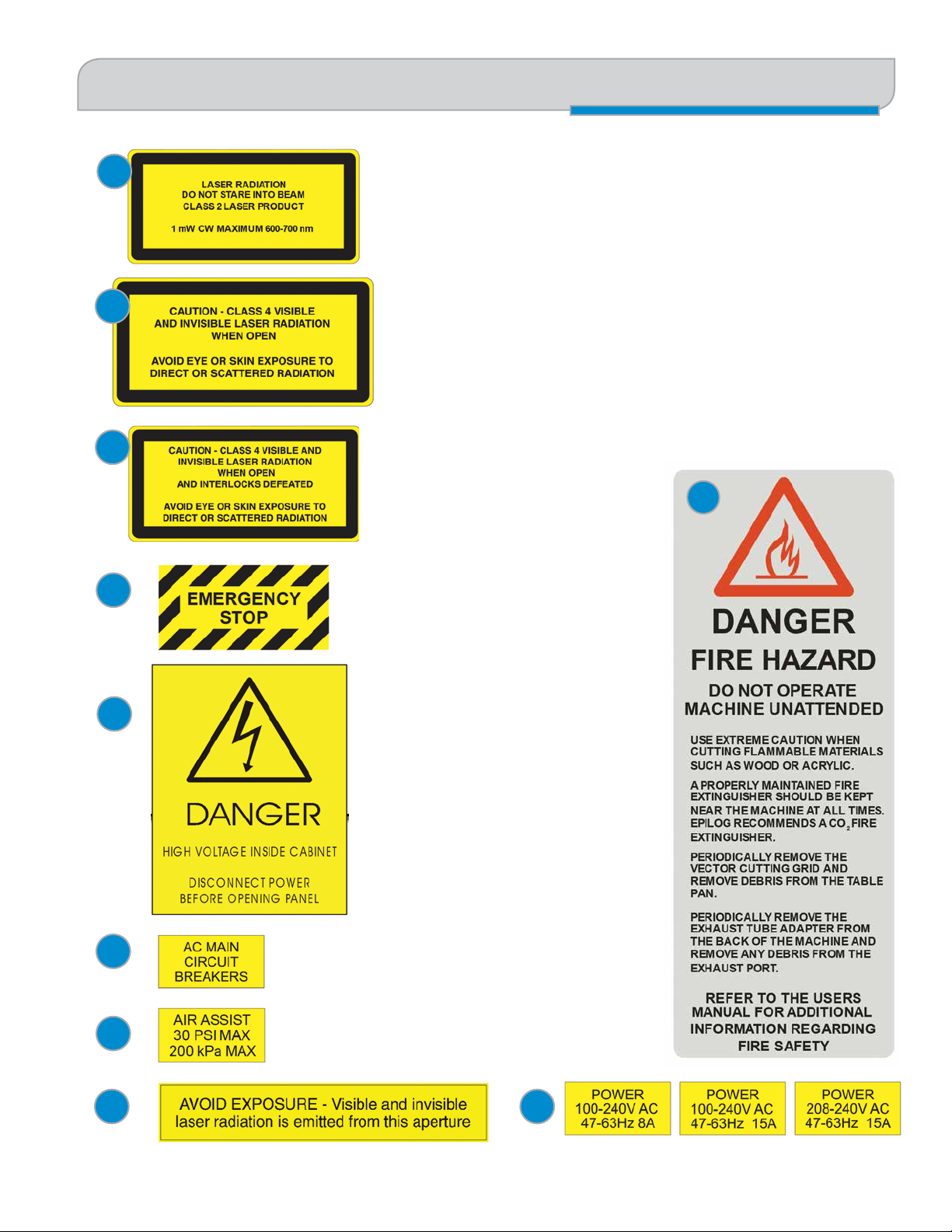
3. Descriptive Label: This label identifies the classification of the Model
13000/14000 in accordance with 21 CFR 1040.10 and IEC 60825-1. It
is located on the left rear of the machine’s cabinet, below the Warning
Logotype.
4. Non-interlocked Protective Housing Safety Labels: These labels are located
on, or adjacent to, removable access covers on the machine’s cabinet as
shown in the diagrams to follow. Where a label is located on a removable
cover, there is an additional label under the cover so that it will be visible
when the cover has been removed.
5. Defeatably-interlocked Protective Housing Safety Labels: There is one label
on each of the machine’s cabinet doors; one on the front door and one on the
top door.
6. Emergency Stop Label: This label is located above the red Emergency Stop
switch on the right front of the
machine’s cabinet.
7. Electrical Safety Label: This label is
located on the power supply module,
inside the bay at the lower righthand side of the machine.
8. Main Breaker Label: This label
is located on or below the power
module panel at the left rear of the
machine’s cabinet.
12
10
7
8
9
9. Air Assist Label: This label is located
on the laser bay cover, at the left rear
of the machine’s cabinet.
10. Aperture Safety Label: This label is
located above the aperture, inside
the cabinet, where laser beams enter
the machine’s engraving area.
11. Power Labels: The appropriate label
for the machine is located on or
above the power module panel at the
left rear of the machine’s cabinet.
12. Fire Warning Label: There are
two labels on top of the machine’s
cabinet; one to the left and one to the
right of the top cabinet door.
11
- 7 -
Page 14
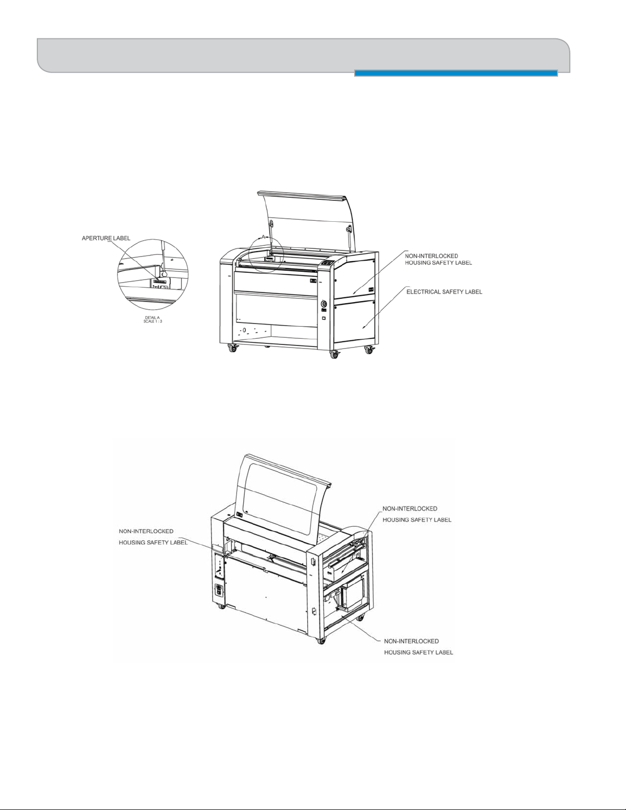
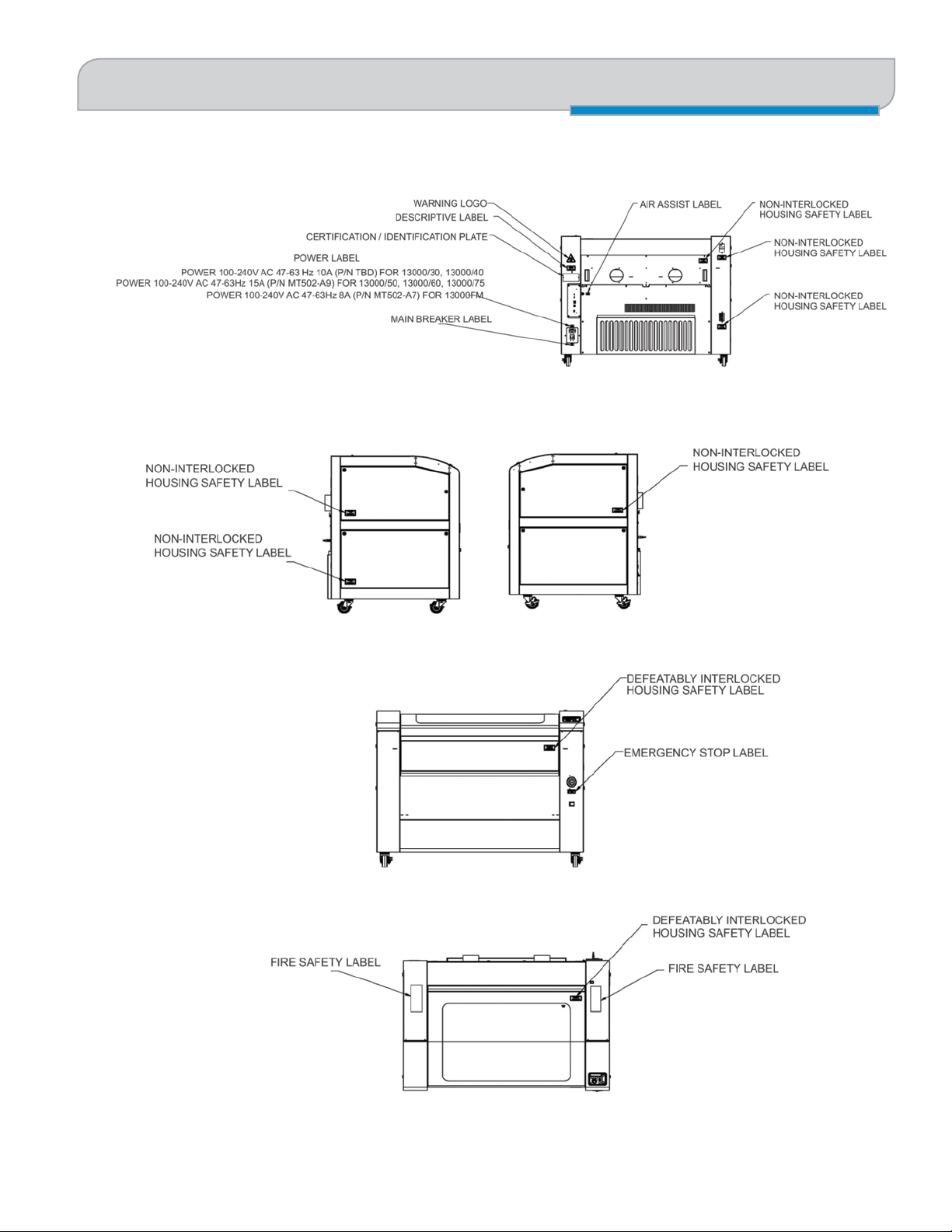
SECTION 1: SAFETY
The following diagrams show the location of each specific label.
Safety Features and Regulatory Compliance
- 8 -
Page 15
SECTION 1: SAFETY
Safety Features and Regulatory Compliance
- 9 -
Page 16
SECTION 1: SAFETY
Do’s and Don’ts
Do’s and Don’ts
Don’ts
Do Not Run the Laser Unvented: Never operate the machine without a properly operating vent to the outside or to a
filtration unit! Most material will only produce an irritating smoke when engraved. Some materials, including but not
limited to paint, varnish, composition board and plastics, produce compounds that can be harmful if concentrated. A
properly installed vent is the only way to ensure that problems do not occur.
Do Not Engrave or Cut PVC: Never engrave or cut any material containing PVC or vinyl. When engraved, a corrosive agent
is produced that will destroy your machine. Your warranty will be void if your machine is damaged by corrosion from
engraving or cutting PVC or Vinyl.
Do Not Operate Machine While Unattended: Never operate your machine without someone watching the system. There
is a significant risk of fire if the machine is set improperly, or if the machine should experience a mechanical or electrical
failure while operating.
Do Not Vector Cut While Machine is Unattended: Never laser cut any material with the laser without someone watching
the system. Because vector cutting moves relatively slowly compared to raster engraving, a tremendous amount of heat
is applied to the material being cut. This buildup of heat can cause significant fire risk and the machine should always be
monitored. Additionally, the Air Assist should always be turned on when vector cutting to reduce the risk of fire.
Do Not Operate The System While Doors are Open: Never operate with any of the covers or enclosures removed, and
never modify the enclosure. The laser beam is invisible and is very dangerous!
Do’s
Clean the System: Please allow a few minutes a week for cleaning your machine. Just a small amount of
effort at the end of the week will pay off with years of trouble free operation of your machine.
See the “Section : Cleaning & Maintenance” on page 85 for specifics.
- 10 -
Page 17

SECTION 2: GETTING STARTED
1. Unpacking the Laser System
Setting up your Epilog Laser System is easy to do! If you’ve ever installed a paper printer, this is only slightly more difficult.
The following information will help you understand the entire system and how it works.
Your Fusion laser system consists of the following components:
1. Fusion Laser System
2. Epilog Driver Disc
3. USB and Ethernet Cables
4. A Preprogrammed Router (eView Camera Module only)
You will also need:
1. A computer or laptop.
2. An exhaust fan: The exhaust fan is mandatory and is used to remove smoke and debris from the Fusion work area.
The exhaust air can be ported to the outside or into a filter box.
Follow these steps to setup your Fusion Laser system:
1. Unpack the laser system.
2. Choose where to locate the system.
3. Connect the exhaust system to your laser.
4. Connect the electrical power.
5. Connect the laser to your computer through USB or Ethernet.
6. Sign up for driver update and register your system at www.epiloglaser.com/register.
1. Unpacking the Laser System
Unpack the laser system from the crate provided by Epilog. Please be sure to hold on to all packing
materials and crating in case you need to move the system in the future.
- 11 -
Page 18
SECTION 2: GETTING STARTED
2. Choose Where to Locate the System
2. Choose Where to Locate the System
Cooling Requirements and Operating Temperatures
All Epilog Laser systems use air-cooled laser tubes. Laser technology is such that the laser tubes generate a lot of excess
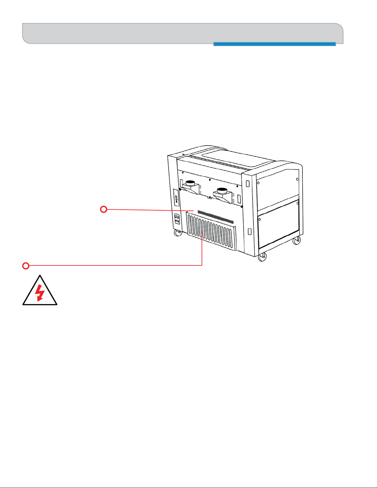
heat and the tubes must be cooled for proper operation. There are cooling fans located at the back of the laser. The fans
and vents should always be clear of restrictions and should never be covered.
Cooling Fans
Laser Tube Air Filter is a standard 12” x 20”
x 1” (304 x 762 x 25 mm) furnace filter and
can be found at any home store. This is more
likely to need to be changed in a dustier shop
environment.
Warning: The cooling fans and vents are located at the back of the Fusion and should never be covered
or blocked in any way. Lasers that overheat will not operate properly and may begin to produce erratic
laser output or possibly complete failure.
Ambient air temperature where the laser system is operating should not exceed 90 degrees F (32 C). Operating in an
environment where the ambient air temperature is above 90 degrees F (32 C) will void the Epilog warranty.
- 12 -
Page 19
SECTION 2: GETTING STARTED
3. Connecting the Exhaust
3. Connecting the Exhaust
In this manual, the term “exhaust” refers to either an exhaust fan or a filter unit and the term “exhaust” is used for
simplicity. The important point is that it is mandatory that an exhaust unit or filter system is incorporated as part of your
laser system. Never operate your laser system without a properly functioning exhaust. The exhaust removes the dust,
debris and smell from the engraving cavity and exhausts it to the outside of the building or to the filter unit. Prior to the
installation of the laser system, you may need a contractor to install the exhaust system. The blower should be mounted
outside your building for noise considerations. Ideally, the blower should not be more than twenty feet (6 meters) from the
laser. You should provide a metal duct (flexible aluminum or galvanized sheet metal) from the blower to the laser. All Epilog
model 13000/14000 laser systems require an exhaust fan that is rated at a minimum of 650 CFM for external exhaust.
Epilog provides recommended exhaust flow rates (CFM) only for direct ventilation exhaust systems that are ported to the
outside. Please note that this is also a recommendation and not a requirement because factors such as length and type
of tubing from the Epilog laser to the exhaust fan and from the exhaust fan to the outside of the building can produce
significant losses on the true amount of air that is drawn from the Epilog laser.
Exhaust flow rates (CFM) for filter systems are not specified in this document. However, exhaust flow rates for filtration
units will be lower than a direct ventilation exhaust systems because filters are designed to be placed directly adjacent to
the laser system and do not exhibit the air-flow losses that are typically found with direct exhaust fans. Epilog has worked
with most major filter manufacturers to recommend a specific filter system for each model of Epilog laser. Please contact
your Epilog distributor to match a filter to the Epilog laser system you are using.
Note: Remember to put the blower switch for the laser system in an obvious and accessible place so it can
be routinely switched on prior to using the engraver. Please connect the exhaust blower to the laser as
shown below and on the following
pages.
Remember, you may need a contractor to install the
exhaust. This must be done PRIOR to installation of
the laser system.
Warning: It’s important that either rigid
or flexible metal ducting be used for all
connections leading to and from the
laser system and the exhaust fan. Vinyl, plastic, or
any type of “soft” ducting is potentially flammable
and should not be used unless provided by the
filtration system manufacturer and made from fireproof materials.
- 13 -
Page 20
SECTION 2: GETTING STARTED
3. Connecting the Exhaust
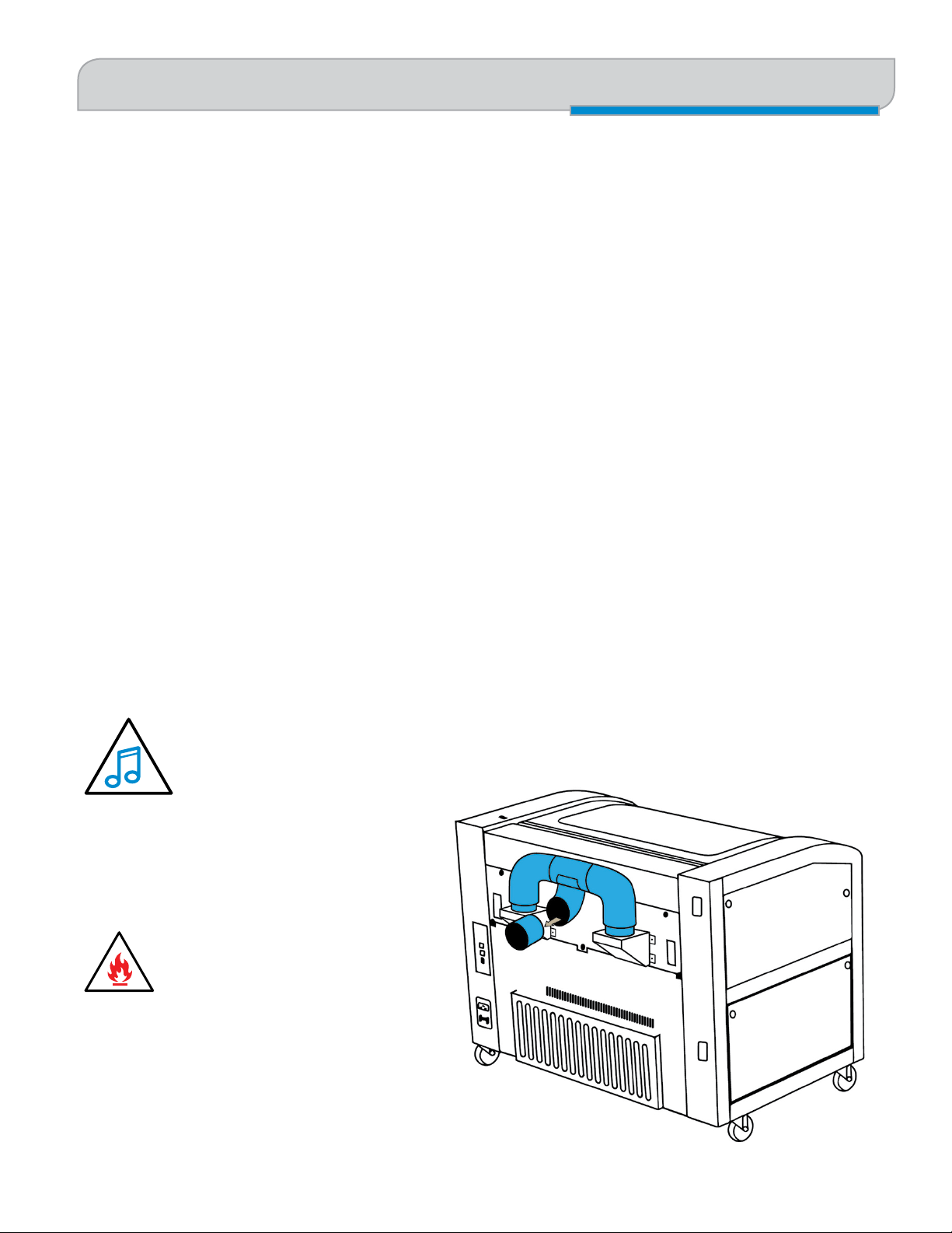
Epilog Exhaust/Filter Connections
There are two 4” (102 mm) ports attached to the back of the laser system. Attach your ducting to the machine as shown
Roof or Exterior Wall
4” (102 mm) flexible
aluminum duct or
rigid galvanized sheet
metal (do not use
vinyl, plastic or “soft”
flexible duct).
in the diagram.
Check your exhaust system for leaks. Most small leaks can be remedied with duct tape. DO NOT OPERATE
your laser with inadequate or leaking exhaust.
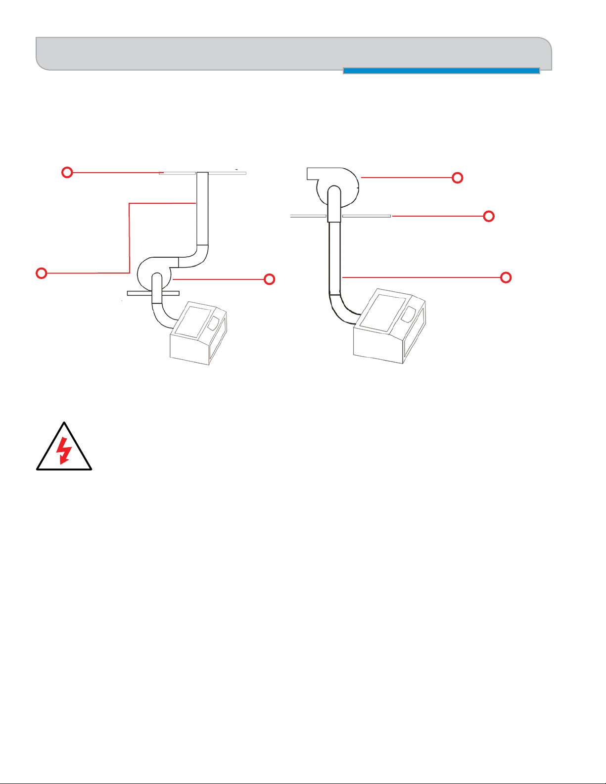
Exhaust Blower
Exhaust Blower
Roof or Exterior Wall
4” (102 mm) flexible aluminum
duct or rigid galvanized sheet
metal (do not use vinyl, plastic or
“soft” flexible duct).
- 14 -
Page 21

SECTION 2: GETTING STARTED
4. Connecting Electrical Power
The drawings below show the typical exhaust setup. The left drawing shows the exhaust near the machine and the right
drawing shows the exhaust fan on the roof. Where the exhaust fan is placed is a choice of personal preference. Some
users like the exhaust fan outside because of noise considerations.
4. Connecting Electrical Power
All Epilog laser systems have an auto-switching power supply that
detects the incoming voltage and automatically switches itself to
operate properly at any single phase voltage between 100 and 240
VAC. The power supply will also automatically compensate for
either 50 or 60 Hz. Epilog supplies the appropriate power cord for
the system you ordered. The power cord is found in the accessory
package with your machine. The power cord for the laser plugs
into the power receptacle located on the left side of the machine in
the rear corner. It is recommended that a dedicated 15 amp circuit
be used if available, but it is not required.
Electrical Connection
110/220 V - 50/60 Hz
The Fusion 120 watt laser system requires 208/220/240 volt electrical
power. This system will not operate on 120 volt power. The Fusion 120 watt power cord comes with a male plug type
NEMA L6-15R (which is a Hubble HBL4570C equivalent).
While the 60 and 75 watt Fusion models can operate on 110 volts, we recommended
using 208/220/240 volt electrical power to achieve maximum performance. If you would like
a 220V cord for your 60 or 75Watt Fusion, please request it at time of ordering.
5. Setting Vector Cutting Table Default
If you have ordered the optional Vector Cutting Table, install it into your system (see “Installation of the Vector Cutting
Table” on page 113). On the Fusion Control Panel, use the Joystick to scroll down until Settings is highlighted. Use the
Joystick to scroll through the options until you see Vector Grid In. This indicates if the Vector Cutting Table is installed.
Center click to gain access, tilt the Joystick up or down to toggle to Yes if the Vector Cutting Table is installed. Press the
Go key to make your change permanent.
6. Connect the Laser to Your Computer
You are now ready to connect your computer to the laser. The following connections can be used:
1. USB only connection: You can use the USB port for the print driver and Epilog Job Manager. Multiple laser systems
cannot be operated from a single computer through the USB connections. If you are using the USB connection, you
- 15 -
Page 22
SECTION 2: GETTING STARTED
7. Set the Fusion’s IP Address
will need one computer for each laser system.
2. Ethernet only connection: With an Ethernet connection you can print from the Laser Dashboard and use the Epilog
Job Manager.
3. If you are using the optional eView Camera Module, you will need to use both USB and Ethernet connection. For
this connection, please see “Attaching the eView Camera System to Your Computer” on page 135.
USB Connection
A USB cable is included in the accessory kit. The USB port is located at
the rear of the machine. USB cables have different connectors on each
end. Before plugging in the USB cable, turn the laser OFF, then connect
one end to the laser and connect the other end into any available USB port
on your computer. After connecting the USB cable, turn the laser back on.
The computer will recognize a new USB device and walk you through the print driver installation. For detailed instructions,
see “Windows 8 and 10: USB Installation” on page 28.
Connect to the laser.
Ethernet Connection
The Ethernet Port is a standard 10BaseT connection. Your Epilog Laser has all of the versatility of a network capable
peripheral. As such, there are many different ways that the laser can be connected to a computer or a network. A direct
connection using a crossover cable is the only method that will be described in this manual. Connect the crossover cable
(included in the accessories kit) to the Ethernet port, located at the back of the machine. Plug the cable into the Ethernet
port on the laser, then plug the other end into the Ethernet port on your computer.
The Epilog Dashboard is the print driver that allows your computer to talk to your Epilog Laser system when either the USB
or Ethernet Crossover cables are connected. The driver is included in the accessories kit on a CD-ROM or on our website
at www.epiloglaser.com. To see detailed instructions on installing the print driver, see “Windows 8 and 10: Ethernet
Installation” on page 25.
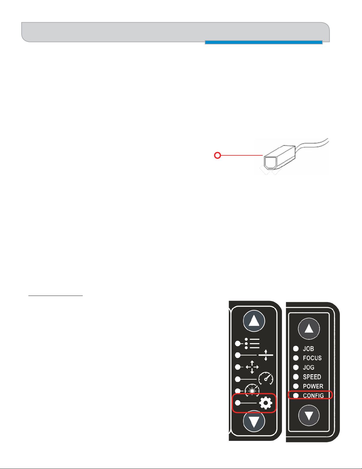
7. Set the Fusion’s IP Address
1. To set the IP Address from the Fusion’s control panel, press the down
arrow until Settings/Config is selected. It’ll vary depending if you have the
symbolic or text keypad.
2. Tilt the joystick down until IP Address appears.
3. Center click to gain access, tilt the Joystick up or down to increment or
decrement. Tilt left or right to move to the different sets of three numbers.
Press the Go key to make your change permanent.
- 16 -
Page 23
SECTION 2: GETTING STARTED
7. Set the Fusion’s IP Address
Most Epilog users will use the IP Address of
192.168.003.004, which is what we use in
this manual.
IP Address
192.168.003.004
4. With CONFIG still selected, tilt the Joystick down
until Subnet Mask appears.
5. Center click to gain access, tilt the Joystick up or
down to increment or decrement. Tilt left or right to
move to the different sets of three numbers. Set the
Subnet Mask to 255.255.255.0. Press the Go key to
make your change permanent.
Subnet Mask
255.255.255.0
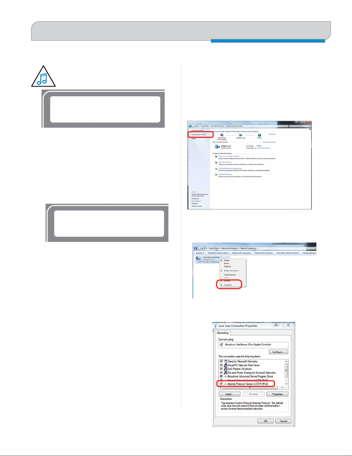
8. Set Up TCP/IP Address in the
Computer
Go to your Network and Sharing Center in your computer’s
Control Panel.
1. Click Change Adapter Settings.
2. Right click Local Area Connection, then click
Properties.
3. Select Internet Protocol Version 4 (TCP/IP). Make
sure you do not select Version 6.
- 17 -
Page 24
SECTION 2: GETTING STARTED
9. Sign Up for Driver Updates and Register Your System
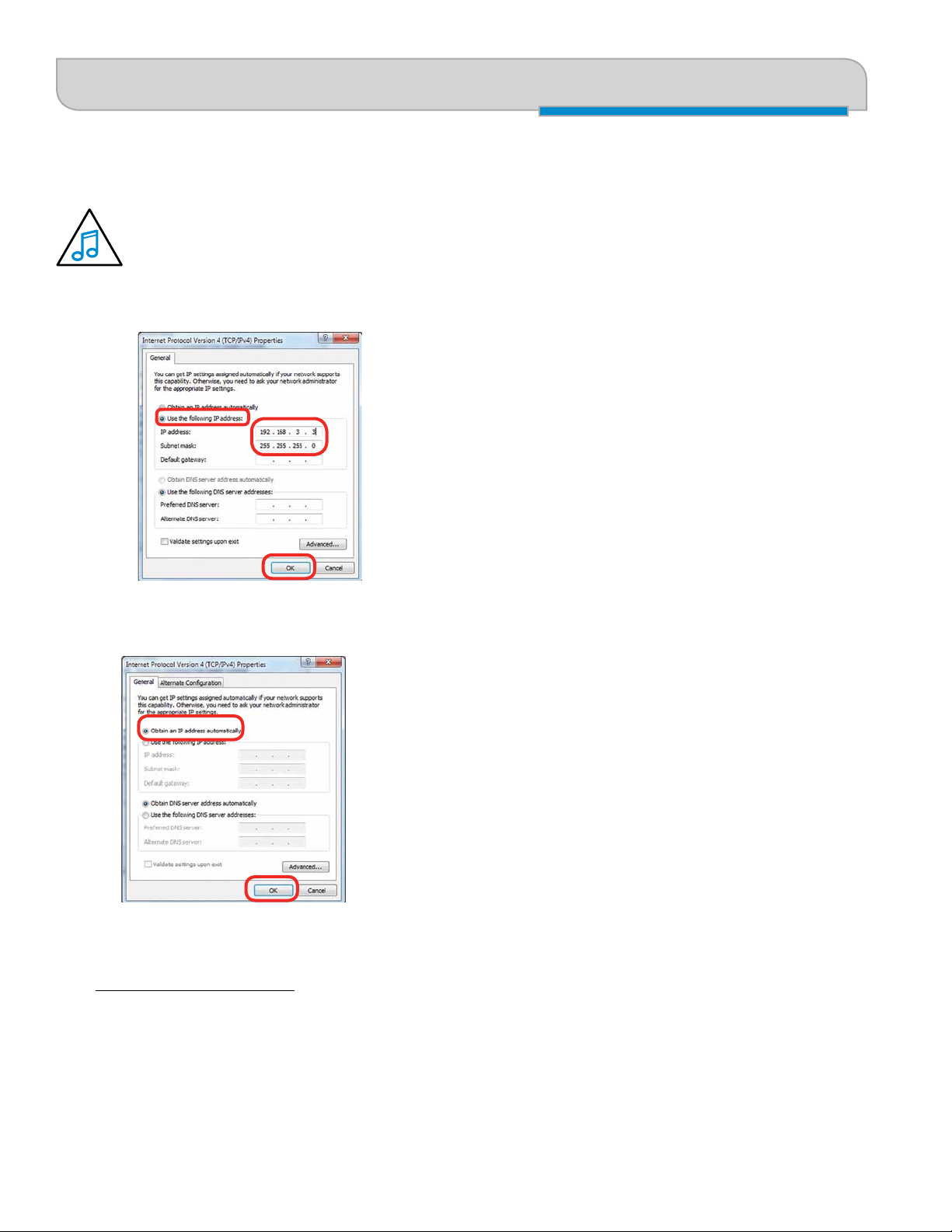
4. If you do not have an eView Camera Module installed, select Use the following IP Address. Type in the following
IP Address: 192.168.3.3.
This number is not an error; the last digit of the IP address in this window must be different than the IP
address you set in the laser.
Type in a Subnet Mask of 255.255.255.0, then click OK.
5. If you do have an eView Camera Module installed, choose Obtain an IP address automatically. Then click the OK
key.
9. Sign Up for Driver Updates and Register Your System
Go to www.epiloglaser.com/register and register your system. You can also sign up for our monthly e-newsletter, quarterly
customer printed newsletter, and sign up for driver update notifications.
- 18 -
Page 25
SECTION 3: DRIVER INSTALLATION
Windows 7: Ethernet Installation
Next we’ll be installing the print driver. Choose your
operating system. We demonstrate Windows 7, 8, and 10
installations.
Windows 7: Ethernet
Installation
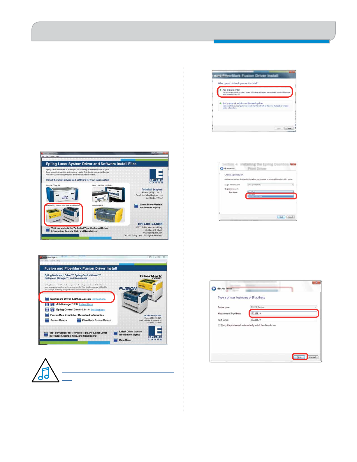
1. Insert the Driver CD in the computer and select your
laser system.
2. Select the Dashboard Driver.
3. Click Add a local printer.
4. Click Create New Port, then click on the drop-down
menu and select Standard TCP/IP Port, then click
Next.
5. Enter the IP Address to match the IP Address you
set at the Fusion laser in “Setting the IP Address”
on page 16. Most Epilog users will use the IP
Address of 192.168.3.4, which is what we use in this
document. After typing in the IP Address, click Next.
Wait while the computer identifies the port.
You can also download the latest driver from
epiloglaser.com/tech-support/epilog-drivers.
htm. Go to Devices and Printers on your
computer and click Add a Printer to start the
process.
- 19 -
Page 26

SECTION 3: DRIVER INSTALLATION
Windows 7: Ethernet Installation
6. Select Custom and then Settings.
7. Set Protocol to LPR. This is a very important step.
Your download time will increase significantly if LPR
is not selected. Type Laser into the Queue Name,
then click OK.
9. Click Have Disk.
10. Click Browse and go to the folder where you saved
the driver and click Open. (The default location is C:/
fusion_drivers.)
8. Click Next.
11. Click EpilogWinALLFusion file and click Open.
12. Click OK.
- 20 -
Page 27
SECTION 3: DRIVER INSTALLATION
Windows 7: Ethernet Installation
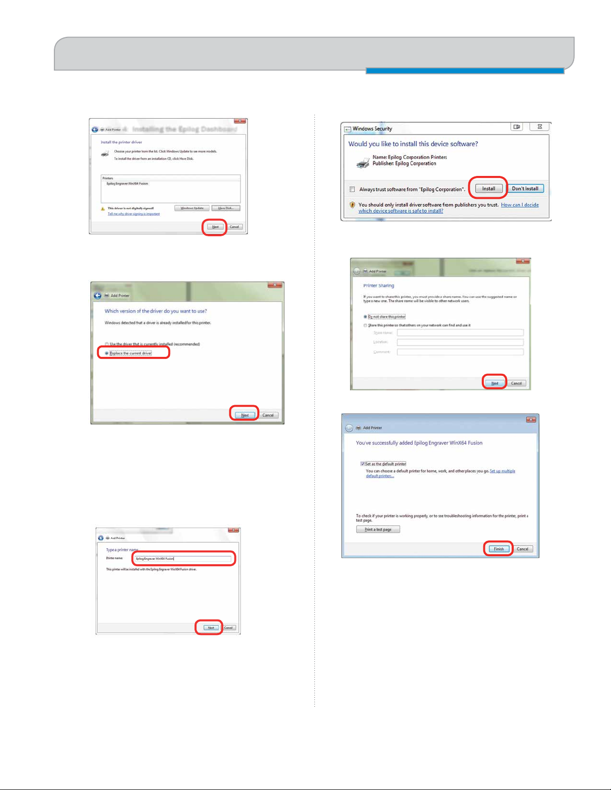
13. Click Next.
14. Click Replace the current driver if requested, then
click Next.
16. If you see this screen, click Install.
17. Click Next.
15. You can rename your printer here. We have not
changed it for this document, but many users like to
associate the driver name with the IP Address they
are using, for example Fusion 192.168.3.4. This is
especially helpful if there is more than one laser
connected to a single computer. Click Next.
18. Click Finish and your driver is installed.
19. You must now restart your computer before you
continue.
20. If you will be printing from CorelDRAW, go to
“Setting Up CorelDRAW Beziers Setting” on page
31.
- 21 -
Page 28
SECTION 3: DRIVER INSTALLATION
Windows 7: USB Installation
Windows 7: USB Installation
Please follow these instructions closely! Using a different
process to install the Dashboard driver is likely to fail if
you are using Windows 7.
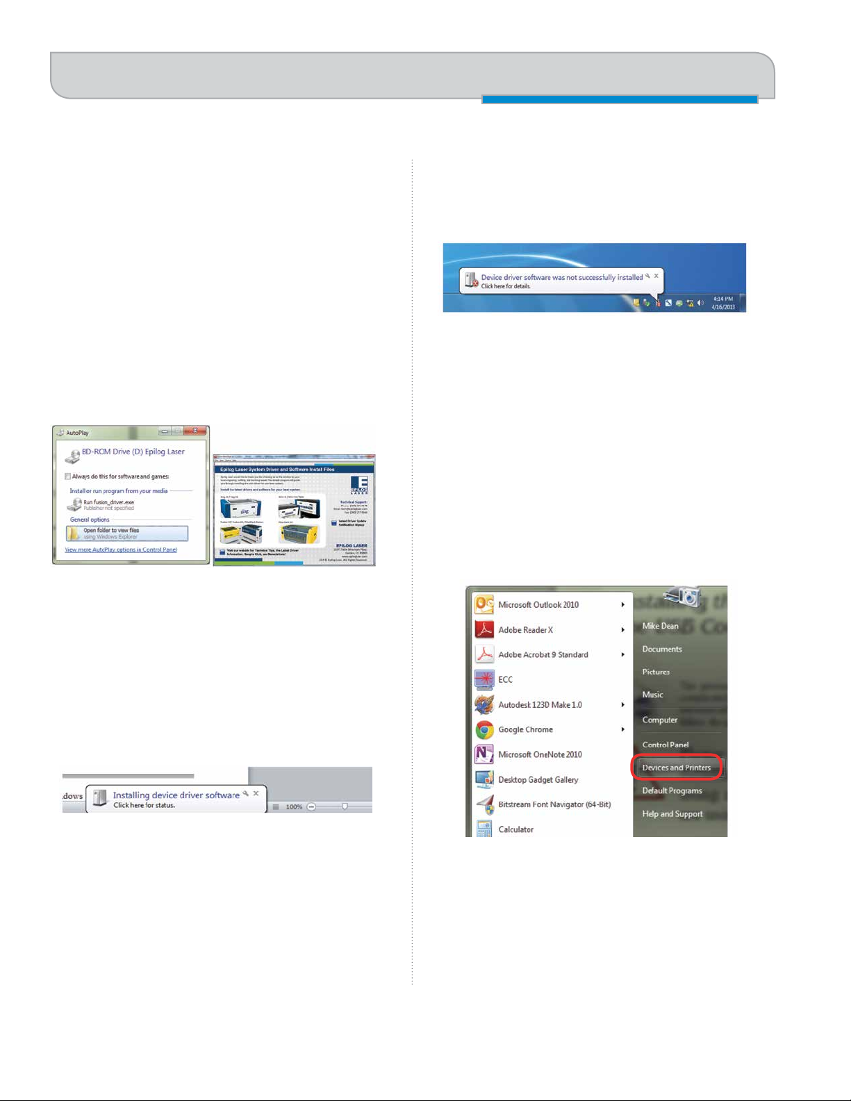
1. Insert the Epilog driver install disc into your
computer (or download the files from the website).
One of the following screens will appear. For the
USB installation, you will want to close them. We do
not want the computer to automatically try to install
the driver.
4. A small window will appear in the lower right corner
of your computer screen that indicates installation
was successful. This is only partially true.
5. After a short wait you will see another small window
that indicates the installation was not successful.
This is what we hope to see and will lead us to
the next step in the process. If your computer is
connected to the Internet, it will take a few minutes
for your computer to display these windows. Please
be patient during this process and let the computer
finish trying to install the drivers. Interrupting the
computer at this point will require you to restart the
process.
6. After the failure notification, go to the Windows start
key (lower left corner of your computer screen).
Click Devices and Printers.
2. With the power of your laser turned off, connect the
USB cable to your computer and your Fusion.
3. Power on your laser system. It will take about a
minute for the laser to initialize. After it initializes it
will start the process of installing the driver. You will
see activity on the USB icon in your system tray
(lower right corner of your computer screen).
- 22 -
Page 29
SECTION 3: DRIVER INSTALLATION
Windows 7: USB Installation
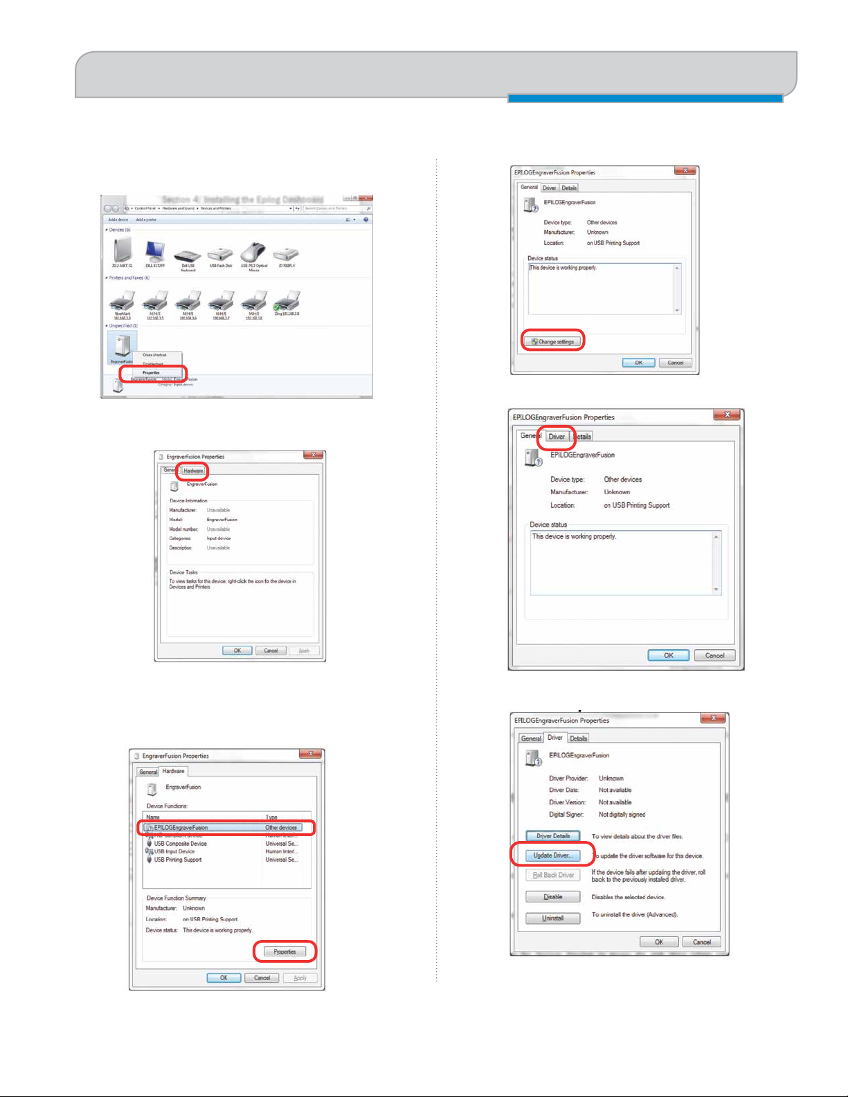
7. Right click on the Fusion, Zing, Mini/Helix, or
FiberMark icon. Then click Properties.
8. Select the Hardware tab.
10. Click Change Settings.
11. Click the Driver tab.
9. Select the device EpilogEngraver then click
Properties.
12. Click Update Driver.
- 23 -
Page 30
SECTION 3: DRIVER INSTALLATION
Windows 7: USB Installation
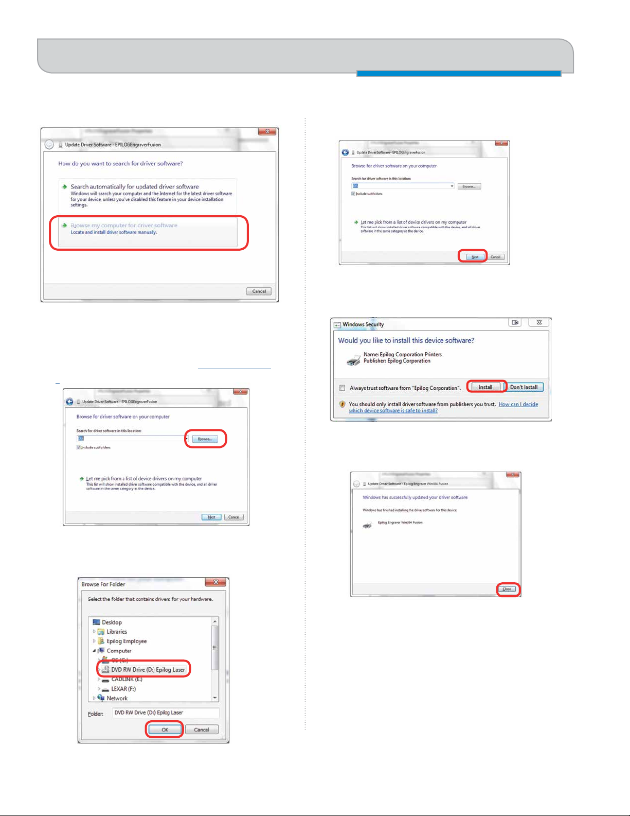
13. Click Browse my Computer for driver software.
14. Use the Browse key to direct your computer to your
disc drive that contains the Epilog driver disc that
you inserted earlier in this process. (You can also
download the latest driver from epiloglaser.com/
tech-support/epilog-drivers.htm.)
16. Once you have the proper disc drive showing click
on the Next key.
17. The progress window will appear.
18. If you see this screen, click Install.
15. For this document we show the DVD RW drive as
the drive where the disc is located.
19. Your Epilog Laser Dashboard print driver has been
successfully installed on the USB port. Click Close.
20. Click Close in the next window and then Close
again. You will then see your laser driver in the
Devices and Printers page. Click on the red X in the
upper right corner of this page. That’s it! You are
ready to print to your laser.
21. If you will be printing from CorelDRAW, go to
“Setting Up CorelDRAW Beziers Setting” on page
31.
- 24 -
Page 31

SECTION 3: DRIVER INSTALLATION
Windows 7: USB Installation
Windows 8 and 10: Ethernet Installation
1. Insert the Driver CD in the computer and select your
laser system.
2. Select the Dashboard Driver.
3. Windows 8 and 8.1/10 have different paths.
Choose your operating system:
In Windows 8:
4. In Windows 8.1/10:
Select The printer that I want isn’t listed.
Click Add a local printer or network printer with
manual settings. Click Next.
You can also download the latest driver from
epiloglaser.com/tech-support/epilog-drivers.
htm. Go to Devices and Printers on your
computer and click Add a Printer to start the
process.
- 25 -
Page 32

SECTION 3: DRIVER INSTALLATION
Windows 8 and 10: Ethernet Installation
5. Select Create a new port, then Standard TCP/IP
Port. Click Next.
6. Enter the IP Address to match the IP Address you
set at the Fusion laser in “Setting the IP Address”
on page 16. Most Epilog users will use the IP
Address of 192.168.3.4, which is what we use in this
document. After typing in the IP Address, click Next.
Wait while the computer identifies the port.
8. Set Protocol to LPR. This is a very important step.
Your download time will be greatly increased if LPR
is not selected. Type Laser into the Queue Name and
click OK.
9. Click Next.
7. Select Custom, then Settings.
10. Click Have Disk.
- 26 -
Page 33

SECTION 3: DRIVER INSTALLATION
Windows 8 and 10: Ethernet Installation
11. Click Browse, browse to the folder where you saved
the download. The default location is c:/fusion_
driver.
12. Click EpilogWinALLFusion file and click Open.
15. Click Replace the current driver if requested and
click Next.
16. You can rename your printer here. We have not
changed it for this document, but many users like to
associate the driver name with the IP Address they
are using, especially if there is more than one laser
connected to a single computer. For example, we
might rename the driver Fusion 192.168.3.4. Click
Next.
13. Click OK.
14. Click Next.
17. If you see this page, click Always trust software
from “Epilog Corporation” then Install.
18. Click Next.
- 27 -
Page 34

SECTION 3: DRIVER INSTALLATION
Windows 8 and 10: USB Installation
19. Click Finish and your driver is installed.
20. You must now restart your computer before you
print to the laser.
21. If you will be printing from CorelDRAW, go to
“Setting Up CorelDRAW Beziers Setting” on page
31.
Windows 8 and 10: USB
Installation
Windows 8 will not automatically walk you through
the installation process so it is important to follow the
instructions below.
minute for the laser to initialize.
4. Once your laser has initialized, there will not be any
real indication on your computer that it is ready to
install the Epilog driver, but it is ready.
5. In Windows 8, open the Charms Bar and click on the
Search charm. To access the Charms Bar move your
mouse into the lower right corner of your display.
6. Type the word Control into the search bar. Click on
the Control Panel box under Apps in the upper left of
this window. In Windows 10, you can search for this
from the desktop.
1. Insert the Epilog driver install disc into your
computer (or download the files from the website).
One of the following screens will appear. For the
USB installation, you will want to close them. We do
not want the computer to automatically try to install
the driver.
2. With the power of your laser turned off, connect the
USB cable to your computer and your Fusion.
3. Power on your laser system. It will take about a
7. Click Devices and Printers.
- 28 -
Page 35

SECTION 3: DRIVER INSTALLATION
Windows 8 and 10: USB Installation
8. In the Unspecified section of Devices and Printers,
right click on the Fusion icon, then click Properties.
9. Select the Hardware tab.
11. Click Change Settings.
12. Click the Driver tab.
10. Select the device EpilogEngraver. Then click
Properties.
13. Click Update Driver.
- 29 -
Page 36

SECTION 3: DRIVER INSTALLATION
Windows 8 and 10: USB Installation
14. Click Browse my Computer for driver software.
15. Use the Browse key to direct your computer to your
disc drive that contains the Epilog driver disc that
you inserted earlier in this process.
17. Once you have the proper disc drive showing click
the Next key.
18. Wait while until the progress window disappears,
then you may be asked if you want to install this
driver. Click Always trust software from “Epilog
Corporation” then Install.
16. Find the disc drive with the Epilog install disc and
click OK.
19. Your Epilog Laser Print Dashboard has been
successfully installed on the USB port. Click Close.
- 30 -
Page 37

SECTION 3: DRIVER INSTALLATION
Setting Up CorelDRAW Beziers Setting
20. In the next window, click Cancel.
21. You will see your driver in the Devices and Printers
page. Click on the red X in the upper right corner of
this window and you are ready to print!
Setting Up CorelDRAW
Beziers Setting
Due to the way that the Fusion series handles vector lines,
there is a setting in CorelDRAW that needs to be changed
for vector cutting to work properly. This only affects
CorelDRAW and is not necessary if you are using other
graphic software.
1. In CorelDRAW, go to Tools > Options.
22. If you will be printing from CorelDRAW, follow the
next steps for Setting CorelDRAW’s Beziers.
2. Under Global > Printing, choose Driver
Compatabilities. Next to Printer choose the Fusion
Laser you just installed. Check the box “Send
beziers and paths to driver” and click OK.
- 31 -
Page 38

SECTION 3: DRIVER INSTALLATION
Mac Driver Installation
Mac Driver Installation
Installing the Epilog Mac Driver for
the First Time
If you already have the Mac Driver installed
and just want to add the ability to work on
Sierra OS, go to “Installing the Mac Driver
on Sierra OS” on page 33.
3. Go to epilogfiles.com/epilog-test/EpilogApps.dmg
and double click to load the file.
4. The following screen will appear. First double click
the GhostscriptInstaller.mpkg file.
6. Click Continue.
7. The software license agreement will appear. Click
Continue.
5. A welcome screen appears. Click Continue.
8. Choose to Read License then click Agree.
- 32 -
Page 39

SECTION 3: DRIVER INSTALLATION
Mac Driver Installation
9. Select Install.
10. Type in the password epilog (lower case) as the
password then click Install Software.
12. Go back to the installer and double click
EpilogInstall.mpkg.
13. The installation process for the EpilogInstaller is the
same as for the Ghostscript file. At the end of the
installation you will be asked to reboot. Reboot to
complete the driver installation.
Installing the Mac Driver on Sierra
OS
To install the Mac Driver on Sierra OS there are a few
additional steps.
11. Press Close to finish the first part of the install.
1. Go to Settings.
- 33 -
Page 40

SECTION 3: DRIVER INSTALLATION
Mac Driver Installation
2. Select Printers and Scanners.
3. Highlight and delete any existing Epilog drivers by
selecting the minus symbol.
5. Click the IP icon.
6. Fill out the following information:
a
Type 127.0.0.1:55000 next to address.
Important! Notice that a colon separates the 1
and 55000.
b
Set Protocol to HP Jetdirect - Socket.
4. Add a new driver by clicking the plus symbol.
Provide a name for the printer. We have named
c
the printer Epilog.
In the Use drop-down menu, click on Select
d
Software.
a
b
c
d
- 34 -
Page 41

SECTION 3: DRIVER INSTALLATION
Mac Driver Installation
7. Select Epilog Corporation Epilog PDE, then click
OK.
8. Click Add.
11. Go to the Finder/Applications.
12. Finally, drag the Epilog icon into the dock.
9. And you’re done! The Mac driver has been installed.
10.
- 35 -
Page 42

Page 43

SECTION 4: THE EPILOG JOB MANAGER
Epilog Job Manager Instructions
Epilog Job Manager
Instructions
The Epilog Job Manager is a powerful new tool that will
quickly become one of your favorite features on your
laser system. From one piece of software, you can access
any job you have sent to the laser, view the settings
you used on any past job, re-run projects, access your
material database, and much more. It’s a great addition to
the Epilog Laser product features, and we look forward to
seeing how our customers use this software!
• Windows 7/8/10 is required to use the Epilog Job
Manager.
How to Install the Epilog Job Manager
3. In Windows 8 or 8.1 you may see this message.
Click More Info.
4. Click Run Anyway.
1. If you have a previous version of the Epilog Job
Manager installed, you must uninstall it before you
continue.
2. On your driver CD, select the Job Manager.
You can also download the Job Manager
from epiloglaser.com/tech-support/drivers.
htm.
5. Click Next.
- 37 -
Page 44

SECTION 4: THE EPILOG JOB MANAGER
How to Install the Epilog Job Manager
6. Click Next.
7. Click Next.
9. Click Next.
10. Click Install.
8. Accept the license, then click Next.
11. The installation will take a few moments.
- 38 -
Page 45

SECTION 4: THE EPILOG JOB MANAGER
Trouble Shooting Job Manager Installation
12. Click Finish and the Job Manager is installed.
13. A Job Manager icon will be automatically added to
your Desktop. You are now ready to use the Job
Manager.
Trouble Shooting Job
Manager Installation
If you were unable to install the Job Manager, it’s possible
that your Anti-Virus software is blocking installation.
To disable Symantec Anti-Virus software, choose
Options. Other anti-virus packages should have
something similar to Symantec.
Disable all Virus and Spyware Protection Features. After
the Job Manager has been installed go back into your
Anti-Virus software and re-enable the setting that was
disabled.
- 39 -
Page 46

SECTION 4: THE EPILOG JOB MANAGER
Important Epilog Job Manager Notes
Important Epilog Job Manager Notes
• Warning: Before activating your laser, install the newest version of the driver to properly associate the
correct machine with the Job Manager.
• We suggest a minimum of 1 GB of free RAM space when managing very large raster and vector jobs.
Using the Epilog Job Manager
Activate a Laser
1. The first time you open the Job Manager you’ll see a tab for each of the models. You will need to activate your laser
system to get started. Click the correct tab, then your system. You can activate multiple machines if you have
more than one laser.
2. To activate your machine:
● Machine Name: Give your machine a name (Fusion M2 32).
● Printer Name: Select your installed laser from the drop-down list.
Important - if you do not choose the correct printer you will not
be able to print from the Epilog Job Manager!
● Serial Number: This is not your machine serial number, but the
USB serial number that can be found in your system’s Settings
menu. On the laser’s control panel, arrow down to Settings, then
move the Joystick down until you see Serial #.
● Select the correct machine series, wattage, etc. The Laser Power is very important because it will automatically
load the proper material setting files for your specific wattage of laser.
- 40 -
Page 47

SECTION 4: THE EPILOG JOB MANAGER
Using the Epilog Job Manager
● Select eView System Installed if you have the
optional eView Camera Module installed.
● Click Save.
3. Your new laser has been activated in the Job
Manager and appears in the left panel. The Job
Manager is now ready to accept jobs from the print
driver.Use the Add or Delete keys to add additional
machines or to remove a laser. Below you can see
we have installed an additional Helix laser system to
the Job Manager.
2. Select the Camera tab, then select the system you
activated from the drop-down list if you have more
than one laser activated. Click Save to finish.
Printing to the Epilog Job Manager
Setting Up the eView Camera
Module
If you have the eView Camera installed on your Fusion
laser system, associate your eView Camera with the
correct laser. Follow the following steps:
1. Click on the Gear icon in the top left corner to open
the Program Settings.
Create a file in your graphic software and set your laser
parameters in the print driver.
In the driver you’ll see a selection available under the
Center-Engraving area. You can choose to print to either
the printer (your laser system), the Job Manager, or both.
This allows you to send your job to the Job Manager
without sending it to the laser so you can then print that
job directly from the Job Manager at a later time without
accessing your graphic software. This is an easy way to
set up an entire day’s jobs all in one place.
- 41 -
Page 48

SECTION 4: THE EPILOG JOB MANAGER
Using the Epilog Job Manager
Organizing Your Print Jobs
Click the Jobs tab. All print jobs will be displayed in the
Uncategorized folder. Click on your job to highlight it. You
can now Print, Edit, Preview or Delete this job using the
available icons.
Create and Delete Job Folders
Click the Add Job Folders icon to add folders. We added
folders for this customer’s three largest customers. You
can add as many folders as you’d like.
Type in the folder name and click the check mark to
create your new folder.
Move an Uncategorized File to a Folder
When you highlight a folder you will see From
Uncategorized on the right side of the folder. Click From
Uncategorized to move a job from the Uncategorized
folder to this subfolder.
and click OK.
Select the job you want to move
- 42 -
Page 49

SECTION 4: THE EPILOG JOB MANAGER
Using the Epilog Job Manager
Create Subfolders
First highlight the folder in the left panel where you want
to add a subfolder. Below we have highlighted the
Anamosa High School folder. Click the Add Subfolder
icon. Type the subfolder name in the Add SubFolder
field, then click the check mark to create the subfolder.
Using the Material Setting
Configurations
The Material Settings tab stores all of the suggested laser
parameters like speed, power, etc. These settings were
loaded based on the wattage you specified in the Laser
System tab (adding your laser was the very first thing
you did to start using the Job Manager).
Move a Job Between Folders
You can also move any job to another folder or subfolder
by double-clicking on the job. Select the Folder and
Subfolder from the drop-down menus where you want to
save the job. You can save the job with the same name or
you can save as a new job. You can also modify your
laser settings and save them with the job. Click Save to
continue.
To use the material settings that are automatically loaded
in your Job Manager, go to the Jobs tab and double-click
on the job you want to process.
Click the Import icon.
- 43 -
Page 50

SECTION 4: THE EPILOG JOB MANAGER
Using the Epilog Job Manager
Navigate to the material setting you need. We have
highlighted 1/8” Cherry/Alder/Walnut 300 DPI. Click OK.
Your new settings have been automatically applied to
your job file. You can now save this file, save the file as a
different name or print from this window. Double clicking
on the artwork will take you to the full preview window,
which is explained in the next frame.
Previewing Your Job
In the Preview mode can preview just the raster
components of your job, or just the vector components.
We have selected vector to show only the vector
components of this job. The preview mode is very useful
in identifying unwanted vector components in a job.
Searching For a Job
The Job Manager has a powerful search function.
Type in part of a file name and press enter to find all files
related to that name.
To view a preview of the job, click on the Preview tab.
You can organize files by category, creation date, print
date, or alphabetically to find a specific file.
- 44 -
Page 51

SECTION 4: THE EPILOG JOB MANAGER
Using the Epilog Job Manager
Notice that the jobs are displayed differently if you
change the search category to Alphabetical. Your jobs
are now displayed in alphabetical order. Once the search
is finished and the job is found, most users revert back to
the default selection of Standard.
Finding Job History
Color Mapping
To access the Color Mapping settings used in a file,
double-click on the file to open the Job Information, then
click the Colors tab.
You can modify the settings, save as a new job, save as
the same job, print, preview, etc from this window.
Click the History tab to see a full print history of a job,
including settings you used in each print. You’ll see what
machine it was printed to, when it was first printed (Initial
Print), all subsequent prints, and all laser parameters
used. To access this, double-click on the job, then select
History.
You can modify, print or save from this window using the
listed settings or with new setting. The new setting will
be saved as the next print job complete with time stamp
and date.
- 45 -
Page 52

SECTION 4: THE EPILOG JOB MANAGER
Using the Epilog Job Manager
Vector Sorting
You can determine the cutting order of vector lines directly
from the Epilog Job Manager.
You can choose from three different vector sorting options:
1. None: Vector line cutting order is determined by the
order they were created.
Changing Program Settings
You can access the Program Settings by clicking on the
gear at the top left of the page.
On this screen you can set several different system
settings, including:
2. Optimized: The laser will process the vector lines
looking for the next closest node for quicker
vectoring.
3. Inside/Out: All internal vector paths in the file will
be process prior to the external vector paths. For
example, if cutting the letter O, the inner oval will be
cut before the outer oval.
Display Tab:
• Language: Choose from several languages.
• Default Length Units: Choose from inches,
millimeters, or centimeters.
Alerts Tab:
Choose when the program asks for confirmation when
you delete machines, folders, subfolder, jobs and
materials, or pages.
- 46 -
Page 53

SECTION 4: THE EPILOG JOB MANAGER
Database Tab:
• Backup Database: Save a backup of all files, material
settings, etc.
• Restore Database: Reload settings from a previous
backup.
• Clear Entire Database: Delete all settings, machines
and jobs from the database.
• Clear All Jobs: Delete all jobs in the database.
• Clear Uncategorized: Clear out all uncategorized
jobs in the database.
Camera Tab:
Set which system has an eView camera attached.
Using the Epilog Job Manager
We will be adding new features to the software often, so
sign up for the Driver Update Notification list at www.
epiloglaser.com/tech-support/epilog-drivers.htm.
- 47 -
Page 54

Page 55

SECTION 5: USING THE LASER DASHBOARD™
Changing Laser Dashboard Defaults
The Epilog Dashboard is the print driver that sends your artwork and laser parameters from the computer to the laser.
The Dashboard is shown below and can be installed from the driver CD that came in your accessories kit. It can also be
downloaded from the Epilog website. If you are just getting started and are in a hurry to engrave a job, you can do so by
setting just a couple of parameters in the Dashboard without having a detailed understanding of what different choices
are available to you.
Note! When using the slider bars, there are several different ways to get the desired setting. These different
methods all follow standard Windows protocol, so they will work in other Windows software applications too.
• Change the settings by clicking on the slider bar to
move it, or type in exact numbers to the right of the slider.
• Holding down the Alt key while clicking close to the slider will bring
up a box outlining the slider and allow you to move in increments of
ten.
The following sections provide detailed explanations of the different features in the Print Driver. Most engraving and
cutting jobs can be accomplished by using only the General tab of the Print Driver. Advanced features for more complex
jobs can be found under the Advanced and Color Mapping tabs.
Changing Laser Dashboard Defaults
If you would like to permanently change any of the settings that we walk through on the next few pages, you can easily
set a new default for each of them.
1. Go to Control Panel | Devices and Printers
2. Right mouse click on the Epilog Engraver.
3. Click Printing Preferences.
4. Change any of the settings. These changes will become the default settings for each new print job.
5. Click OK and close out all open windows.
When would you want to do this?
Most users set their defaults to match the materials they use the most. They might set the speed default to 100% because
they only engrave acrylic. They might only vector cut so they set the default Job Type to vector, or they might set the page
size to match the size of the engraving table. By following these quick steps you can make sure that these are the settings
you see every time you open the print driver.
- 49 -
Page 56

SECTION 5: USING THE LASER DASHBOARD™
General Tab
General Tab
The General Tab is where you will find 90% of the features you will utilize when sending jobs to the laser. Everything from
resolution to speed and power settings are all located on this one page.
5
1
6
2
3
4
1
Resolution
Set your print resolution from 75 to 1200 DPI. For the best engraving results, use a resolution equal to the resolution in
the raster images within your project setup. The resolution setting in the print driver will affect the engraving time (there
are twice as many engraved lines at 600 DPI as at 300 DPI) and the quality. For a detailed discussion on Resolution, visit
“Resolution” on page 79.
7
8
9
10
2
Center Engraving
The Center Engraving Option allows you to define the center of your artwork as the primary reference point (Home
Position) of your engraving or cutting job. The Center Engraving Option has been designed to be used in conjunction with
the Jog feature on the Fusion Control Panel. Center engraving differs from standard printing where the upper left corner
of the page and the upper left corner of the laser table define your primary reference point. For more information, visit
“Center Engraving” on page 106 in the manual.
3
Rotary Options
Use this check box if you are using the optional 3-Jaw Chuck Rotary Attachment. With this Rotary Attachment you will
need to enter the material’s diameter in this selection. See “3-Jaw Chuck Rotary Attachment” on page 125 for more
information.
- 50 -
Page 57

SECTION 5: USING THE LASER DASHBOARD™
General Tab
4
Job Manager Features
You can choose to print to either the printer (your Fusion Laser), the Job Manager, or both. This allows you to send your
job to the Job Manager without sending it to the laser so you can then print the job directly from the Job Manager at a later
time without accessing your graphic software. This is an easy way to set up an entire day’s jobs all at one time.
5
Laser Type
The same Fusion driver is used to control either the CO2 or the fiber laser depending on your machine configuration. If a
function does not apply to the laser type installed in your machine, that function will be grayed out. You’ll also see a note
reminding you that if you have the Optional Dual Source (CO2 and fiber) laser system, you will need to use Color Mapping
if both CO2 and fiber are used in the same project. For more information see “Setting Up a Dual Source Job” on page
146.
6
Auto Focus
Check this box when you want to use machine’s Auto Focus capabilities. Measure the thickness of the material you are
using and input the number into the Thickness box. Before the job starts the table will automatically move up or down so
that the top of your material is the correct distance from the bottom of the focus lens. If the Auto Focus box is not selected,
the table will not move up or down when the job starts.
When the Vector Grid is installed and you want to use Auto Focus, click both the Auto Focus box and the Vector Grid box.
This tells the laser system that the Vector Grid is installed and it will automatically compensate for the combined thickness
of the grid and your material.
Offset
Offset allows you to focus at any point above or below the surface of your material. When engraving acrylic many users
like to focus above the surface to produce a “softer” finish to the engraving. Conversely, when cutting acrylic, many users
like to focus about half way into the acrylic. Offset allows you to do this automatically. A positive value will move the table
away from the focus lens. A negative value, such as -.095, will move the table closer the focus lens.
The material thickness is still required when using the Vector Grid. If a thickness is not specified the system
will Auto Focus to the top of the Vector Grid, not to the top of your material. For a detailed discussion on Auto
Focus, visit “Auto Focus vs. Manual Focus” on page 93.
- 51 -
Page 58

SECTION 5: USING THE LASER DASHBOARD™
General Tab
7
Job Type
Choose between the three modes of operation.
• Raster Mode: Used for engraving or marking materials. Typical uses include engraving clipart, scanned images,
photos, text and graphic images. Vector lines that you want to engrave rather than cut should be set 0.006” (0.152
mm) or greater line thickness.
• Vector Mode: Selected when you are running only cut lines or for use with the Red Dot Pointer for previewing the
job processing area. For vector mode, a line is recognized as a line to be cut based on the line width (or stroke).
These lines can also be affected by resolution. For more information, see “Setting a Vector Cutting Line” on page
78. To make things easy, set any cut lines to a line width of 0.001”, or hairline width in CorelDRAW.
• Combined Mode: Used when you engrave and cut in the same job. The laser will always engrave first, then follow
with the vector mode.
Note on Vectors: If you are in Vector or Combined mode, all thin lines will be vector cut! This can be
disconcerting because even if the lines are not visible in your artwork they will still cut. Usually, this happens
when incorporating a clipart image that has hidden lines that are not readily apparent. Please refer to “Setting
a Vector Cutting Line” on page 78 for an illustrated explanation of how this can affect your work.
8
Piece Size
Enter the size of the page you used when creating your artwork. Some laser users prefer to design their piece with a page
size matching the page they are engraving, while others prefer to design with the page size set to the full engraving table.
9
Raster Settings
Speed: Determines the travel speed of the carriage in Raster mode and is adjustable in 1% increments from 1 to 100%.
The slower the speed, the deeper the engraving. Speed settings are heavily dependent on the hardness and the thickness
of the material being engraved with harder materials requiring slower speeds for deeper engraving. Slower speed settings
will produce greater depth of engraving. Please refer to “Appendix B: Material Settings” on page 193 in this manual.
Power: Determines the amount of laser energy that is delivered to the piece being cut and is adjustable in 1% increments
from 1 to 100%. The higher the power, the deeper the engraving. Please refer to “Appendix B: Material Settings” on page
193 in the manual.
Engrave Direction: This feature applies to raster engraving only and allows you to engrave your project either from the
top-down or the bottom-up direction. In standard top-down engraving there can be a large amount of engraving debris
generated, especially on materials such as plastic, wood and rubber. As the debris moves toward the exhaust plenum,
some of it collects in the area that has just been engraved. Bottom-up engraving prevents the debris from collecting in the
freshly engraved spaces.
- 52 -
Page 59

SECTION 5: USING THE LASER DASHBOARD™
General Tab
Dithering: This setting defines how the dot patterns will be engraved in raster images that contain grayscale images,
blends, or color. The Dashboard offers six different dithering patterns to enhance your engraving projects. The default
mode is Standard. This mode can be used for all images, including photographs, but some images improve when engraved
with other dithering patterns Dithering is used only for Raster engraving and has no effect on vector cut lines. For more
information, go to “Image Dithering” on page 96.
10
Vector Settings
Speed: Determines the travel speed of the carriage in vector cutting mode and is adjustable in 1% increments from 1
to 100%. The slower the speed, the deeper the cut. Most cutting applications require relatively slow speed settings,
and the speed is heavily dependent on the hardness and the thickness of the material being cut. Slower speed settings
will also produce better edge quality. High speeds are provided for draft mode only and are not intended for production
applications. For more information, visit “Appendix B: Material Settings” on page 193.
Power: Determines the amount of laser energy that is delivered to the piece being cut and is adjustable in 1% increments
from 0 to 100%. The higher the power, the deeper the cut. The amount of power necessary to cut completely through a
given material is also heavily dependent on the hardness and the thickness of the material. For more information, visit
“Appendix B: Material Settings” on page 193.
Frequency: The number of laser pulses that the laser fires per inch of travel. The frequency is set in the dashboard and
can be adjusted from 1 to 100. A lower frequency number will have the effect of less heat because fewer pulses are being
used to cut the material. Lower frequency rates are helpful for products like wood, where charring is evident at higher
frequencies. High frequencies are useful on materials like acrylic where a large amount of heat is desirable to melt or flame
polish the edges.
Speed Comp: Reduces all speed settings by one half. For example, a speed setting of 10 without Speed Comp selected
will move twice as fast as a setting of 10 with Speed Comp selected. In essence, Speed Comp provides an alternative set
of speed parameters that are one half the speed of the standard settings. Speed Comp mode will most often be used with
speed settings below 10 when very slow cutting is desired. Most users will rarely use Speed Comp mode, but it creates
additional functionality for unusual or demanding applications.
Power Comp: When checked Power Comp reduces the laser output when the laser carriage slows as it moves through a
curve. Consider it a slow cutting option. Selecting Power Comp is especially useful for vector cutting jobs that incorporate
a large number of curves.
Most users find that keeping Power Comp selected is the preferred setting.
- 53 -
Page 60

SECTION 5: USING THE LASER DASHBOARD™
Advanced Tab
The advanced tab contains advanced features including 3D, stamp mode and configurations.
1
2
4
3
Advanced Tab
1
Raster Type
Basic Mode: This is the mode you will use for most engraving projects. The laser will use a uniform engraving speed and
power for the graphic, providing a consistent engraving.
3D Mode: When selected, instead of looking at the dots and determining where to fire the laser based on the dot spacing,
we look at the dots and determine how much laser power (wattage) to apply to each dot, allowing us to create a 3D effect
when deep engraving in materials like wood. For more information go to “3D Engraving” on page 161.
Stamp Mode
The stamp option automatically converts your artwork into to a format that will produce a laser engraved stamp. This
function automatically inverts your artwork so that the background is engraved away while your text and graphic images
are left standing. It also puts a supporting shoulder around every component of the artwork.
2
Stamp Settings
The stamp option automatically converts your artwork into to a format that will produce a laser engraved stamp. This
function automatically inverts your artwork so that the background is engraved away while your text and graphic images
are left standing. It also puts a supporting shoulder around every component of the artwork. Because of the unique nature
of Stamp mode, we have devoted a sub-section on all aspects of stamp making and printing. Please see “Rubber Stamps”
on page 168 in this manual for detailed instructions on producing and printing
- 54 -
Page 61

SECTION 5: USING THE LASER DASHBOARD™
Select Stamp to enable stamp
mode options.
Shoulders: Adjusts the angle
of the sides of the stamp.
Widening: Adjusts the
boldness of the character.
Mirror: Inverts the artwork.
Fence: Defines outer borders.
3
Update Firmware
Advanced Tab
When you are ready to update your Fusion firmware, click here and load the file. For more information, visit “Section :
Upgrading the Operational Firmware” on page 155.
Configurations
The Configurations feature is a comprehensive data management tool that is used to save all of your Dashboard
4
settings for individual jobs. Saving the Dashboard settings as a database file allows you to retrieve the job parameters
at a later time. This saves you the trouble of trying to remember what speed and power and other settings you used on a
job you did three months ago. All of your settings can all be stored as a permanent record.
For example, in this database we have settings for acrylic, coated steel, glass, and many more. After each configuration file
name, you can see if the saved settings are for a Raster, Vector or Combined job, the resolution, and the piece size within
that file. To use any of these settings, click the Load key.
If you find a setting you would like to save into a new configuration file, simply create the settings within the three Laser
Dashboard tabs, then click Save.
The Driver Disc has a number of preset configuration files available. When you unzip your selected wattage’s configuration
files, they will save to c:/epilog/engraving setting. This is the default folder that the Laser Dashboard will look in to load
files available for your laser. After you have found the configuration files you want to use, click on the General tab to see
the settings that the loaded file brings up.
- 55 -
Page 62

SECTION 5: USING THE LASER DASHBOARD™
Color Mapping Tab
Color Mapping Tab
The Color Mapping feature is an advanced feature that must be checked to activate. Color Mapping is designed to be used
in either Raster mode or Vector mode, but not in Combined mode. While Color Mapping is a very powerful tool, most
operators use it for a few main reasons:
1
2
• Using color to define different levels of focus. Many objects need to be marked at different locations that are at
different relative heights. Using color mapping to change the focus in a single job setup is a convenient way to make
marking complex parts simple.
• Using different colors allows users the ability to sequence the order that objects will be marked.
• Setting different speeds and powers for vector mode. Many users, especially architects, want to score some parts of
their artwork and then cut all the way through other parts. Color Mapping allows them to set up unique speed and
power settings for each activity, all in a single job setup.
Color Mapping accomplishes these tasks by assigning laser attributes to the different colors in your artwork. The functions
that can be controlled by color are: Speed, Power, Frequency, Focus, Raster On/Off, Vector On/Off, Air Assist On/Off. For
a detailed look at the Fusion’s Color Mapping capabilities, visit “Color Mapping” on page 97.
3
1
Enable Color Mapping
When this check box is selected, the laser will use the settings assigned to each color. For any colors that are in your
artwork, but not in the color mapping settings, the General settings will be used.
2
Adjust Settings
- 56 -
Page 63
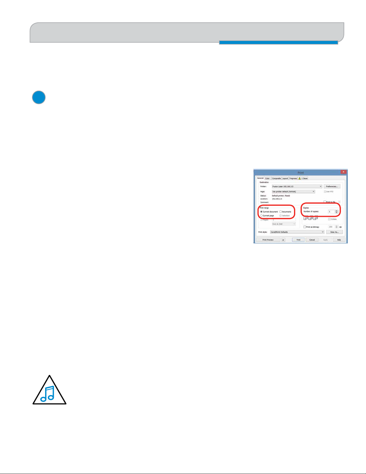
SECTION 5: USING THE LASER DASHBOARD™
Additional CorelDRAW Laser Dashboard Features
Use the slider bars to create any RGB color and set the laser parameters. Adjusting the settings does not actually change
the values. Select the Right Arrow key to finalize the settings.
3
Color Map Summary
The Color Map Summary area is located on the right side of the window and offers a visual display of all of the color
mapped settings. You can quickly see each color and the speed, power, frequency, focus, mode and Air Assist settings for
each of the different colors within your file.
Additional CorelDRAW Laser Dashboard Features
Each program you use will provide different ways to manage these functions.
CorelDRAW offers a very straight forward way to access each of these features.
Multiple Passes
You can automatically engrave or cut a job multiple times by setting the Number of
Copies to the number of passes that you want to make. When each pass is finished
the laser will automatically start another pass until all passes are complete.
Print Range
If you only want to print one aspect of your project (for example, just the text in the document), you can select that part of
the file, then click Selection and the laser will only engrave or cut that piece of your file.
Multiple Pages
When you want to engrave multiple pieces within one document, such as five different engraved glass mugs, each with a
different name, you can use the Multiple Pages feature of CorelDRAW. Set up each of the mug files on a separate page in
your single CorelDRAW file, then when you print to the laser you can choose either Current document to print all of the
pages or you can specify which pages you want to print by adjusting the settings in the Print range box. You can view the
different pages in the Print Preview screen.
When a multiple page job is printed to the laser, each of the pages will transfer to the Control Panel with
the first file coming across as Job:1. File Name, then Job:2. Page 2, Job: 3.Page 3. Remember, the last
page of the job will be the current file when you go to the Fusion’s control panel, so scroll back to Job 1:
File Name to run that one first.
If you start engraving the jobs and become uncertain about which pages are which, you can refer back to your print
preview screen and the Page number in the laser will correspond to the page number in the print preview.
- 57 -
Page 64

Page 65

SECTION 6: USING THE EPILOG MAC DRIVER
Mac Driver Settings
Mac Driver Settings
The Mac Driver is a powerful software tool that allows you to engrave and cut directly to your CO2 Fusion Laser from a
Mac. Here we demonstrate how to print from Adobe Illustrator, but there are other graphic software programs you can
print from to the laser as well.
1
Select Printer
1
Select your Fusion Laser system as your the printer.
2
Options
Job Type: Choose between the three modes of operation.
• Raster Mode: Used for engraving or marking
materials. Typical uses would be reproducing clipart,
scanned images, photos, text and graphic images.
• Vector Mode: Selected when you are only running
cut lines or for use with the Red Dot Pointer for
previewing the job processing area. For vector mode,
a line is recognized as a line to be cut based on line
width (stroke).
• Combined Mode: Used when you have both
engraving and cutting in the same job. The laser will
first engrave your artwork, then follow with the vector
mode.
Center-Center: The Center Engraving Option allows
you to define the center of your artwork as the primary
reference point (Home Position) of your engraving or cutting. The Center Engraving option has been designed to be used
in conjunction with the Jog feature on the Fusion Control Panel. Center engraving differs from standard printing where
the upper left corner of the page and the upper left corner of the laser table define your primary reference point. For more
information, visit “Center Engraving” on page 106 in the manual.
2
3
4
5
Auto Focus: Check this box when you want to use machine’s Auto Focus capabilities. Measure the thickness of the material
you are using and input the number into the thickness box. The table will automatically move up or down so that the top
of your material is 2” (50.8 mm) from the bottom of the focus lens. If the Auto Focus box is not selected, Auto Focus will
be disabled and the table will not move up or down when the job starts.
When the Vector Cutting Table is installed and you want to use Auto Focus, click both the Auto Focus box and the
Vector Grid box. This tells the laser system that the Vector Cutting Table is installed and it will automatically calculate the
appropriate focal distance based on this information.
- 59 -
Page 66

SECTION 6: USING THE EPILOG MAC DRIVER
Mac Driver Settings
The material thickness is still required when
using the Vector Cutting Table. If a thickness
is not specified the system will Auto Focus to
the top of the Vector Cutting Table, not to the top of your
material. For a detailed discussion on focusing the laser,
visit “Auto Focus vs. Manual Focus” on page 93.
Direct Print: The direct print check box is for use only
when you want to send a job directly to the engraver
without first going through the Epilog Viewer.
3
Raster Settings
Speed: Determines the travel speed of the carriage in
Raster mode and is adjustable in 1% increments from 0
to 100%. The slower the speed, the deeper the engraving.
Speed settings are heavily dependent on the hardness
and the thickness of the material being engraved with
harder materials requiring slower speeds for deeper
engraving. Slower speed settings will produce greater
depth of engraving. Please refer to “Appendix B: Material
Settings” on page 193 in this manual.
Power: Determines the amount of laser energy that
is delivered to the piece being cut and is adjustable in
1% increments from 1 to 100%. The higher the power,
the deeper the engraving. Please refer to “Appendix B:
Material Settings” on page 193 in the manual.
Engraving Direction: This feature applies to raster
engraving only and allows you to engrave your project
either from the top-down or the bottom-up direction. In
standard top-down engraving there can be a large amount
of engraving debris generated, especially on materials
such as plastic, wood and rubber. As the debris moves
towards the exhaust plenum, some of it collects in the
area that has just been engraved. Bottom-up engraving
prevents the debris from collecting in the freshly engraved
spaces.
default mode is Standard. This mode can be used for all
images, including photographs, but some images improve
when engraved with other dithering patterns Dithering is
used only for Raster engraving and has no effect on vector
cut lines. For more information, go to “Image Dithering”
on page 96.
4
Vector Settings
Speed: Determines the travel speed of the carriage in
Vector cutting mode and is adjustable in 1% increments
from 1 to 100%. The slower the speed, the deeper the
cut. Most cutting applications require relatively slow
speed settings, and the speed is heavily dependent on
the hardness and the thickness of the material being
cut. Slower speed settings will also produce better edge
quality. High speeds are provided for draft mode only and
are not intended for production applications. For more
information, visit “Appendix B: Material Settings” on
page 193.
Power: Determines the amount of laser energy that
is delivered to the piece being cut and is adjustable in
1% increments from 0 to 100%. The higher the power,
the deeper the cut. The amount of power necessary to
cut completely through a given material is also heavily
dependent on the hardness and the thickness of the
material. For more information, visit “Appendix B:
Material Settings” on page 193.
Freq: The Frequency is the number of laser pulses that
the laser fires per inch of travel. The frequency is set in
the dashboard and can be adjusted from 1 to 100. A lower
frequency number will have the effect of less heat because
fewer pulses are being used to cut the material. Lower
frequency rates are helpful for products like wood where
charring is evident at higher frequencies. High frequencies
are useful on material like acrylic where a large amount of
heat is desirable to melt or flame polish the edges.
Dithering: This setting defines how the dot patterns will be
engraved in raster images that contain grayscale images,
blends, or color. The Dashboard offers six different
dithering patterns to enhance your engraving projects. The
- 60 -
Speed Comp: Reduces all speed settings by ½. For
example, a speed setting of 10 without Speed Comp
selected will move twice as fast as a setting of 10 with
Speed Comp selected. In essence, Speed Comp provides
Page 67

SECTION 6: USING THE EPILOG MAC DRIVER
Mac Driver Settings
an alternative set of speed parameters that are ½ the speed of the standard settings. Speed Comp mode will most often be
used with speed settings below 10 when very slow cutting is desired. Most users will rarely use Speed Comp mode, but
it adds additional functionality for unusual or demanding applications.
Power Comp: When checked, power compensation reduces the laser output when the laser carriage slows as it moves
through a curve. Selecting Power Comp is especially useful for vector cutting jobs that incorporate a large number of
curves. This has the effect of producing unparalleled edge quality when cutting curves. Most users find that keeping Power
Comp selected is the preferred setting.
5
Resolution
Set your print resolution from 75 to 1200 DPI. For the best engraving results, use a resolution equal to the resolution in
the raster images within your project setup. The resolution setting in the print driver will affect the engraving time (there
are twice as many engraved lines at 600 DPI as at 300 DPI) and the quality. For a detailed discussion, visit “Resolution”
on page 79.
- 61 -
Page 68

SECTION 6: USING THE EPILOG MAC DRIVER
Project Setup
Project Setup
While the Mac Driver will work with many different graphic
software packages, we’ll be looking at Adobe Illustrator for
this example.
1. Click the Epilog icon to open the Epilog Viewer.
2. In this example, we’ll set up an Aztec Calendar
engraving and cutting project. We’ve set up our
graphic on our page and are ready to select File/
Print.
4. Click on the Layout drop-down menu and select
Epilog Settings.
5. Set your laser Settings. We’ve set our Job Type to
Combined because we’ll be both engraving and
cutting in this job. For Raster Settings, we’ve used
50% speed, 100% power. For Vector Settings,
we’ve used 30% speed, 70% power. Finally, our
resolution has been set to 600 DPI.
When you have your settings how you’d like them,
choose Print.
3. The standard Illustrator print window will come up,
which will be different depending on which version
of Mac OS you are using. Set your Printer to Epilog
Engraver and PPD to Default (Epilog PDE). Click
Setup to access the laser settings.
- 62 -
Page 69

SECTION 6: USING THE EPILOG MAC DRIVER
Vector Cutting Lines
6. You will return to this print window, so click Print.
7. The driver will now transfer the job to the Epilog
Viewer. The Epilog Transfer icon will appear in the
Dock. The transfer will take several seconds.
8. Once the Epilog Transfer Icon disappears, the Epilog
Viewer Icon will bounce up and down and you can
click on the icon to access the Epilog Viewer.
It’s important that the Epilog Viewer is open
before printing. If it is not open, pause the
transfer in the processing window, open the
Epilog Viewer, and restart the transfer.
9. In the Epilog Viewer, click Edit Settings if you want
to change any print settings, or click Print if the job
is ready to send to the laser.
Vector Cutting Lines
1. Unlike Windows, the Mac Driver allows you to set
the line width that will be cut in the driver. For this
file we have some lines that will be engraved and
some that will be cut. The cut lines we set to 0.23
pixels, while the engraved lines we set to 1 pixel
width.
2. At the bottom right corner of the screen type .3 in
the Vector Less Than box. This will cut any line that
is less than .3 pixels in width and engrave any
above that amount.
- 63 -
Page 70

SECTION 6: USING THE EPILOG MAC DRIVER
3. To see which lines will be cut, click Preview Final.
In the Epilog Viewer, you can see which lines are
vectors and ready to be cut. Click on Preview Final
and the vector lines less than 1 px will be shown in
red.
Vector Cutting Lines
- 64 -
Page 71

SECTION 7: FUSION CONTROL PANEL
Display
Display
The display shows valuable information associated with the highlighted Functional Menu items. We will explain the different
information that will be displayed as we go through the description of each menu item.
International Symbolic Version:
US English Version:
Go
Pause
Reset
Pointer
Laser On
Data
Job
Focus
Jog
Speed
Power
Settings / Config
- 65 -
Pointer
Laser On
Page 72

SECTION 7: FUSION CONTROL PANEL
Display
Go Button
• Press the Go key to start or resume a job.
Pause / Stop Button
• Pressing the Pause key will stop the lens carriage and the laser beam will be shut off. If the Pause key is pressed
during raster engraving mode the lens carriage will pause on either the far left or far right of the engraving line that
is in process. If the Pause key is pressed while in vector cutting mode, the lens carriage will stop at the end of a line
segment or at the next line node location.
• Once the lens carriage has stopped, you can open the door to examine the engraving. By closing the door and
pressing the Pause key, the engraving/cutting job will commence where it left off. If the item being engraved is not
moved the engraving/cutting registration will not be affected.
•
• If you press the Pause key while in vector mode it may take some time for the system to actually stop. The system
needs to get to the next node in a vector before it can stop.
Note: Opening the door on the laser during engraving or cutting will stop the laser from firing; however,
the lens carriage will continue to move. It is important to stop the job before you open the door to insure
the engraving/cutting is completed.
Reset Button
• Pressing the Reset key will move the carriage back to its Home Position. Press the Reset key after you have pressed
the Pause key, or after you have moved the carriage when in the Jog position.
• Reset does not erase the job from the laser systems memory; rather
it will stop the engraving job in process and send the carriage back to
the Home Position.
Left
Up
Right
Data Transferring
This light will illuminate when data is being passed to the laser. This is a
handy tool when you are checking to see if your laser is connected to your
computer.
Down
- 66 -
Page 73

SECTION 7: FUSION CONTROL PANEL
Display
Pointer
The Pointer key is a toggle switch that turns the laser system’s Red Dot Pointer on and off. When the Red Dot Pointer is on, the
indicator light directly to the left of the pointer key will be illuminated. For more information visit “Red Dot Pointer” on page 104.
Laser On
The Laser On key allows you to move the carriage and fire the laser without having a job in the display. This is a very handy
feature because it allows you to do simple tasks without printing a job to the laser system.
To use the Laser On feature you must be in Jog mode, with the door closed. When in Jog mode, press and hold the white
Laser On key. Simultaneously use the Joystick to move the carriage. When the carriage moves, the laser will fire. As soon
as the carriage stops moving the laser will stop firing.
You can adjust the default laser power being used in Laser On mode from the Settings menu. Highlight Settings, then use
the Joystick to scroll down to Jog Laser PWR. Center click the Joystick and then tilt the Joystick Up or Down to change
the value. Press the Go key to activate the change. Go back to Jog mode to use Laser On.
Job
• The Jobs selection allows you to use the Joystick to scroll through the jobs in your laser system. You will be able
to see the job in the first line of the display. The estimated job time and the print resolution will also show on the
second line of the display.
• The job name displayed is the same name as the file name that you printed to the laser.
• When the job you want has been selected, press the Go key in the action keys to start the job.
• After the job starts, the job timer in will be activated and will be shown on the second line of the display.
- 67 -
Page 74

SECTION 7: FUSION CONTROL PANEL
Display
Focus
The Focus selection allows you to manually set the table to the correct height for engraving. With Focus highlighted, use
the Joystick to move the table up or down. The display will show a digital readout of the table position.
The image below also shows two visual indicators that provide addition functionality to the Focus function:
• The two arrows on the left side of the second line in the display indicate whether you are in “Course” or “Fine” focus
mode. In Course mode the table will move up or down in large increments. In Fine mode the table will move up or
down in small increments.
• Tilt the Joystick left or right to toggle between fine and course movements.
Two diamonds indicates that you will double
Job: 1. Fusion_test.cdr
FOCUS -0.000
♦
♦
click the Joystick to access the sub-menu. One
diamond will display for a single click menu item.
Course or fine movement indicator.
Focus Sub-Menu: New Z-Axis Home Position
The two diamonds on the bottom right of the display indicate that by double center clicking the Joystick you will bring up
a sub-menu that will allow you to set a new or temporary table z-axis Home Position. To set a new Home Position, first
move the table up or down in the focus menu, then double click the Joystick at bring up the sub-menu:
<--
GO 0
<--
SET 0
• Up (Go): Tilt the Joystick up to move the table to its default zero/zero Home Position.
• Down (Moveout): Tilt the Joystick down to move the lens carriage out from its upper, left corner position by about
2” (50 mm).
MOVEOUT
RESTORE
<--
<--
- 68 -
Page 75

SECTION 7: FUSION CONTROL PANEL
Display
• Left (Set): Tilt the Joystick to the left to set a new or temporary z-axis Home Position.
Note: The SET 0 function is only used to set or reset a new or temporary Home Position for your table
height when using the Color Mapping function in the Dashboard driver. Auto Focus will not work
properly once a new 0 (zero) table Home Position has been established.
When you set a new 0 (Zero) position for your table, the Auto Focus function in the driver will no longer reference
the default table height. It will reference the new Table Home Position, rendering Auto Focus useless.
You must RESTORE Table Home to re-establish the default Table Home Position if you want to start using Auto
Focus again.
• Right (Restore): Tilt the Joystick to the right to restore the table height to its default Home Position. This is normally
done when you are finished with your new or temporary Table Home Position and want the table to move back to its
default Home Position so you can start using Auto Focus again.
Note: An alternative method of setting a new Table Home Position is to just center click once while in the
Focus Menu. There is no visual indicator on the display, but a single center click after you have focused your
table eliminates double center clicking to access the sub-menu.
JOG
The Jog function allows you to move the laser head around the table with the use of the Joystick. To make it easier to
use, turn on the Red Dot Pointer for a visual indicator of where the carriage is moving. The carriage can be moved in X,
Y or diagonally. The display will show a digital readout of the carriage position.
Jog Sub-Menu: Setting a New X/Y Axis Home Position
The Jog function is most useful for setting a new or temporary Home Position when working on odd shaped items or if it’s
just more convenient to designate somewhere other than the upper left corner of the table as your starting point. To set a
new Home Position, use the following instructions:
1. Go to the Jog function on the Control Panel.
2. Use the Joystick to move the carriage to a new position. Use the Red Dot Pointer as a visual indicator of the
carriage location. The display will also show a digital readout of the X and Y position.
3. Double center click to access the sub-menu:
• Up (Go): Tilt the Joystick up to move the carriage back to its zero/zero position. This function will move the lens
carriage back to a new or temporary Home Position.
• Down (Exit): Tilt the Joystick down to exit the sub-menu. Center clicking does the same thing.
- 69 -
Page 76

SECTION 7: FUSION CONTROL PANEL
Display
• Left (Set): Tilt the Joystick left to set a temporary (new) XY Home Position.
• Right (Restore): Tilt the Joystick to the right to reset the lens carriage back to its upper left corner position after you
are finished using a new or temporary Home Position.
<--
Speed
GO 0
<--
SET 0
Note: An alternative method of setting a new Home Position is to just center click once while in the Jog menu.
There is no visual indicator on the display, but a single center click eliminates the need to access a sub-menu.
EXIT
RESTORE
<--
<--
With Speed highlighted, the speed setting will be displayed. The display will show RS for Raster Speed and VS for Vector Speed.
Power
With Power highlighted, the power setting will be displayed. The display will show RP for Raster Power and VP for Vector Power.
Settings/Config
With Settings highlighted, use the Joystick to scroll through the available menu items.
There are two different modes of operation in the Settings menu:
• Functions: Any menu item with a diamond (
perform that function.
• Adjustment (Calibrations): These are menu items that can be changed. There is not a diamond in front of these
items, but center clicking is used to allow access to the function. After center clicking to gain access, use the
Joystick to increment, decrement or toggle the value that is shown. Press the Go key to make your change
permanent.
♦) in front of it is a function. Simply center click on the Joystick to
The items in the Settings menu are shown below along with a description of how they are used:
♦ Restore XY Home: Center click to restore the lens carriage to its standard Home Position when you are finished
1.
using a temporary Home Position. You can Restore XY Home from here or you can double center click in Jog mode
to do the same thing.
- 70 -
Page 77

SECTION 7: FUSION CONTROL PANEL
Display
2. ♦ Restore Table Home: Center click to send the table back to its default Home height. You can Restore Table Home
from here or you can double center click in Focus mode to do the same thing.
3. X Home: This is a calibration function that insures your artwork is properly located on the table in the X-axis. It is
set relative to the upper left corner of the table and the readout shows increments of .001” (.025 mm).
● Center click to gain access, tilt the Joystick up or down to increment or decrement. Press the Go key to make
your change permanent. These settings will not go into effect until you Restore Table Home (see above) or turn
off the system.
● Increasing this number has the effect of moving your artwork to the right. If you increase the value from -123 to
-121 will move the X Home to the right by .002” (.051 mm).
● Decreasing this number has the effect of moving your artwork to the left.
4. Y Home: This is a calibration function that insures your artwork is properly located on the table in the Y-axis. It is
set relative to the upper left corner of the table and the readout shows increments of .001” (.025 mm).
● Center click to gain access, tilt the Joystick up or down to increment or decrement. Press the Go key to make
your change permanent. These settings will not go into effect until you Restore Table Home (see above) or turn
off the system.
● Increasing this number has the effect of moving your artwork down.
● Decreasing this number has the effect of moving your artwork up. If you decrease the value from 23 to 20 you
will move the Y Home up by .003” (.076 mm).
5. Table Home: This is a calibration function that insures your Auto Focus distance is set properly. It establishes the
correct spacing between the focus lens and the top of the table. It insures that the table always moves the top of
your work piece to a point that is exactly two inches below the focus lens (or, three inches for the Fiber lens) when
Auto Focus is used. The readout shows increments of .001” (.025 mm).
● Center click to gain access, tilt the Joystick up or down to increment or decrement. Press the Go key to make
your change permanent.
● Increasing this number has the effect of increasing the distance between the table and the lens carriage.
● Decreasing this number has the effect of decreasing the distance between the table and the lens carriage.
6. Fiber Offset: This is a setting found on Fusion M2 systems that have both CO2 and fiber lasers installed. This
setting is a factory installed setting.
7. Vector Grid Home: A calibration for adjusting the Z-Home Position of the Vector Grid when installed.
8. Jog Laser PWR: This function sets the laser power that will be used when using the Laser On feature. Increasing
this number increases the percentage of the laser power that will be used when Jogging the lens carriage and
pressing the white Laser On key.
● Center click to gain access, tilt the Joystick up or down to increment or decrement. Press the Go key to make
your change permanent.
♦ Quick Table Home: A center click will move the table down to find the nearest table height sensor. This function
9.
is rarely used.
- 71 -
Page 78

SECTION 7: FUSION CONTROL PANEL
Display
10. Serial #: This establishes a serial number for USB use. Center click to gain access, tilt the Joystick up or down to
increment or decrement. Press the Go key to make your change permanent. This function is rarely used.
11. IP Address: This sets the IP Address of the laser system. Center click to gain access, tilt the Joystick up or down
to increment or decrement. Tilt left or right to move to the different sets of three numbers. Press the Go key to
make your change permanent.
12. Subnet Mask: This sets the Subnet mask for the laser system. Center click to gain access, tilt the Joystick up or
down to increment or decrement. Tilt left or right to move to the different sets of three numbers. Press the Go key
to make your change permanent.
13. Gateway: This sets the Gateway for the laser system. Center click to gain access, tilt the Joystick up or down to
increment or decrement. Tilt left or right to move to the different sets of three numbers. Press the Go key to make
your change permanent.
14. Laser Installed: This is a factory setting that is not user accessible and shows which type laser is installed in the
machine - CO2, Fiber, or both. CO2 lasers are the most versatile and work with many different types of materials.
Fiber lasers are used for metal marking only.
15. Vector Grid In: This indicates if the Vector Cutting Table is installed. Center click to gain access, tilt the Joystick up
or down to toggle between Yes and No. Press the Go key to make your change permanent.
16. AirA Raster: This tells the machine to activate Air Assist during all Raster jobs. Center click to gain access, tilt the
Joystick up or down to toggle between Yes and No. Press the Go key to make your change permanent.
17. AirA Vector: This tells the machine to activate Air Assist during all Vector jobs. Center click to gain access, tilt the
Joystick up or down to toggle between Yes and No. Press the Go key to make your change permanent.
18. CO2 Laser Match: This sets the left-right raster line alignment for the CO2 laser. This setting is normally a factory
only setting and will not need to be adjusted by the user.
19. Fiber Laser Match: This sets the left-right raster line alignment for the fiber laser. This setting is normally a factory
only setting and will not need to be adjusted by the user.
♦ Set XY Home: This sets a new Home Position. Most users find it is easier to make this setting from the sub-
20.
menu in Jog mode.
♦ Set Table Home: This sets a new Table Home Position. Most users find it is easier to make this setting from the
21.
sub-menu in Focus mode.
♦ Go XY Home: This restores the carriage lens to its default Home Position in the upper left corner of the machine.
22.
Most users find it is easier to make this setting from the sub-menu in Jog mode.
23. Auto Delete: This setting allows you to have jobs automatically delete after running. You will typically want to have
this setting turned to No.
♦ Go Table Home: This restores the table to its default Home Position.
24.
25. X Scale Adjust: This setting calibrates the accuracy in the X-axis. This setting is normally a factory only setting and
will not need to be adjusted by the user.
26. Y Scale Adjust: This setting calibrates the accuracy in the Y-axis. This setting is normally a factory only setting and
will not need to be adjusted by the user.
- 72 -
Page 79

SECTION 7: FUSION CONTROL PANEL
Display
27. Laser TI: This sets the Tickle of the laser tube. This setting is normally a factory only setting and will not need to be
adjusted by the user.
28. Pulse Stretch: This sets the Pulse Stretch of the laser tube. This setting is normally a factory only setting and will
not need to be adjusted by the user.
29. Table Speed Adj: This adjusts the speed of the table and is normally a factory only setting that should not be
adjusted by the user.
30. Bed Size: This indicates the bed size. This setting is normally a factory only setting and will not need to be adjusted
by the user.
31. System Unit: Sets the units of the machine to inches or millimeters.
32. Fiber Laser Power: This the wattage of the fiber laser source and should not be changed by the user.
♦ Full Table Home: This setting resets all temporary Home Positions and reestablishes the default Home Position
33.
that is found at boot up.
34. Raster Tune Adj: This fine tunes raster engraving mode and is normally a factory only setting that should not be
adjusted by the user.
35. Vector Tune Adj: This fine tunes the vector cutting mode and is normally a factory only setting that should not be
adjusted by the user.
36. Calibrate Joystick: This setting is normally a factory only setting. It reestablishes the feel of the Joystick.
37. Rotary Installed: This displays if a Rotary Attachment is currently installed.
38. Rotary Version: This displays the Rotary version that is installed.
39. Y Drive Version: This displays the Y Drive version that is installed.
40. X Drive Version: This displays the X Drive version that is installed.
41. Passcode: The passcode feature on the Fusion laser allows you to create a passcode to lock the factory set
machine functions within the Settings menu so they cannot be changed accidentally.
To Establish a Passcode:
• Go to the Settings menu on the Fusion Keypad and tilt the Joystick up until you see Passcode 0000.
• Center click the Joystick to gain access and show the cursor.
• Tilt the Joystick up or down to increment or decrement the first number. Tilt the Joystick left or right to
increment or decrement the next number. Continue the process until you have set a four-digit Passcode
number.
• Write down your Passcode and save it in a secure place!
• Press the Go key to exit and display your Passcode.
• To finalize the lock process, tilt the Joystick down while still in the Settings menu until you see the Lock
Config menu item.
- 73 -
Page 80

SECTION 7: FUSION CONTROL PANEL
• Center click the Joystick.
• Press Go to lock the code or Pause to exit the menu.
• After locking the Passcode, access to all machine factory settings from within the Settings menu will be
visible, but will be locked out so they cannot be changed accidentally.
• Machine functions such as Restore XY Home, Quick Table Home, etc will not be locked out and can still be
used from the Settings menu.
Verify the Settings/Config Menu Has Been Locked
• To verify that your Passcode has been locked, tilt the Joystick Up until the menu reads Passcode XXXX.
Disable Your Passcode
• Go to the Settings Menu on the Fusion Keypad.
• Tilt the Joystick Up to the Unlock Config menu item.
Joystick
• Center click the Joystick to gain access and display the cursor.
• Tilt the Joystick Up, Down, Left and Right to enter your Passcode.
• Press the Go key. Your Passcode will now to displayed, but it has been unlocked.
• Your Fusion is unlocked any time you can read the four-digit Passcode.
• Your Fusion is locked any time the Passcode reads XXXX.
♦ Lock Config: Locks and unlocks the Settings/Config menu in conjunction with the Passcode (see above).
42.
43. System Version: This displays the Firmware version that is installed.
Joystick
The Joystick is used to control, move, or change all of the available features found in the Fusion Control Panel. After you
highlight a Function Menu item you will use the Joystick to control, move or change that function by tilting or depressing
the Joystick.
Changes made while using the Joystick will be shown on the two-line LCD display. The Joystick is an extremely versatile
tool that can be used in many different ways.
There are four primary functions to control the Joystick:
• Tilting: Many actions will be performed by tilting the Joystick from side-to-side or up and down. The Joystick
provides 360 degrees of maneuverability. The Joystick is progressive in that a slight tilt will produce a small or slow
movement while a greater tilt will produce a faster or larger movement.
- 74 -
Page 81

SECTION 7: FUSION CONTROL PANEL
Job Storage: Temporary Memory
• Center Click: This is accomplished by simply pressing straight down on the center of the Joystick. A special ♦
character is used in the display to indicate functions where a center click action is used. For example, use the
cursor keys on the Control Panel to scroll to the Settings function. The first setting will read
The diamond that is in front of Restore XY Home indicates that a center click will restore your lens carriage to the
upper left Home Position.
♦ Restore XY Home.
• Double Center Clicking: A double diamond
is available when a double center click is initiated. The Focus and Jog functions both provide a sub-menu when a
double center click is used.
• Flick: A single, quick “flick” will produce a single movement or very small adjustment.
The Joystick is progressive and touch sensitive and provides a continuously variable range of adjustments. It is sensitive
to the degree of tilt that is being applied. The more you tilt the Joystick, the bigger your impact on the function you are
using.
♦ ♦ in the lower right corner of the display indicates that a sub-menu
Now you try it!
1. Use the cursor keys on the Control Panel to highlight the Jog function. Jog mode moves the lens carriage. Now,
simply tilt the Joystick as far as you can to the right and down. The lens carriage will start moving, slowly at first,
then after a second it will start picking up speed. To slow the carriage, simply reduce the amount of tilt you apply to
the Joystick. Varying the amount of tilt changes how fast the carriage moves.
2. Now, let’s “flick” the Joystick. By flicking the Joystick, the carriage will move about .001” or .002”. You will
probably not be able to see the motion, but if you watch the display panel you will see that the digital readout
changes.
3. Once you get a feel for it, you will be able to move the carriage at an absolute crawl or as fast as it will go just by
adjusting the amount of tilt.
Job Storage: Temporary Memory
While there is no key for this, the Fusion laser has the capability to store multiple jobs in temporary memory. The machine
will store any and all jobs sent until there is no free temporary memory left. For all practical purposes, there is no limit to
the number of jobs you can send to the laser.
Note: Temporary jobs stored in the laser systems will be erased when the laser system is turned off. For
permanent job saving, print the file to the Job Manager, where you can file the job for later retrieval along with
all settings you used in the past.
- 75 -
Page 82

Page 83

SECTION 8: QUICK START GUIDE
Artwork Setup
Artwork Setup
Create your job in the graphics software of your choice, such as CorelDraw or Adobe Illustrator. There are three different
modes of operation for the laser and the way you setup your artwork will determine if you raster engrave, vector cut, or
use combined mode.
Raster Engraving
Raster engraving can best be described as very high
resolution dot matrix “printing” with a laser. Raster
engraving is used to create highly detailed graphic
images. The laser head scans back and forth, left to right,
engraving a series of dots one line at a time. As the laser
head moves down line by line, the dot pattern forms the
image that was printed from your computer. You can raster
engrave scanned images, text, clipart, photographs, or line
drawings.
This artwork is a good representation of a raster file. The
photograph of the tiger will raster engrave, as will the text
that has been placed on the page.
Vector Cutting
When you are vector cutting, the laser is following a continuous
path that follows the outline, or profile, of an image. Vector
cutting is normally used to cut completely through materials
such as wood, acrylic, paper, etc. It can also be used for quick
marking of characters and geometric patterns. You can vector
cut with the laser by setting objects and text to be unfilled and
drawn with a 0.001” (0.025 mm) outline. The thin outline will
produce a vector cut.
This graphic shows a vector image made up of lines. You can
tell it is a vector image because you can individually select any
of the lines and manipulate that part of the graphic.
When vector cutting, we always suggest that you use the Vector Cutting Table or Pin Table to protect the back of your
material as well as your table from laser marking.
- 77 -
Page 84

SECTION 8: QUICK START GUIDE
Setting a Vector Cutting Line
Note: If your raster artwork contains thin lines between .001” (.025 mm) and .007” (.177 mm) depending on
resolution, and you are using Vector or Combined mode, those thin lines will all vector cut. The most common
setup where this occurs is when you have a clipart image with hidden lines that you send to the laser using
Combined mode. The artwork shown below is a good example of a piece of clipart as it appears on the screen (top) and
the hidden lines (bottom) that will vector cut if you are in Combined or Vector mode. If you only want to raster engrave,
make sure you select Raster mode in the Epilog Dashboard.
In CorelDraw you can view just the lines (bottom view) by clicking on the View key in the menu bar and selecting Simple
Wire Frame. The upper image is a complex piece of clipart. The lower image shows all of the hidden lines that are in this
piece of clipart. If this clipart image were run in Combined mode, it would first raster engrave most of the car then vector
cut any of the thin lines below .007” (.177 mm). You can also use the Preview function of the Epilog Job Manager to view
only vector lines. See “Previewing Your Job” on page 39.
Clipart that looks like it is a raster
file is actually often made up of
small lines. If the lines are set too
thin, then it may cut as well as
engrave if you send it to the laser in
combined mode.
Setting a Vector Cutting Line
The laser determines which lines to engrave or cut based on the width (stroke) of each line. If you’re using CorelDRAW,
any line set to hairline width will cut. But in other software what width should you set a line to? Different line weights will
engrave and cut at different widths and resolutions.
The table below shows various line widths and which will cut at the different resolutions. To be safe, set all vector lines to
.004” (.101 mm) or less to make sure they will always cut.
Line Width 150 DPI 200 DPI 300 DPI 400 DPI 600 DPI 1200 DPI
.001” (.025 mm) Cut Cut Cut Cut Cut Cut
.002 (.058 mm) Cut Cut Cut Cut Cut Cut
.003 (.076 mm) Cut Cut Cut Cut Cut Cut
.004 (.101 mm) Cut Cut Cut Cut Cut Cut
.005 (.127 mm) Cut Cut Cut Engrave Engrave Engrave
.006 (.152 mm) Cut Cut Cut Engrave Engrave Engrave
.007 (.177 mm) Cut Cut Engrave Engrave Engrave Engrave
- 78 -
Page 85

SECTION 8: QUICK START GUIDE
Resolution
Where do I set the Vector Line Width?
Different software packages set the line width in
different places. In CorelDRAW, you can find the
outline width in the top menu bar when a vector line is
selected. In Adobe Illustrator it is called the stroke
width and you can find this setting in the Stroke Panel.
If you can’t select a line to set the width,
it may be because it is part of a grouped
object. Try to ungroup the object, then
select the line. You also can’t select an
individual line if that line is part of a raster image.
Resolution
Print quality is commonly referred to as Resolution and is one of the variables that determine image quality. Resolution is
expressed in dots per inch (DPI) and is determined by the number of lines or dots that are engraved for every inch of
movement. Each horizontal line is referred to as a raster line. The higher the resolution setting, the finer the detail that can
be achieved. Keep in mind that engraving resolution is only one factor in determining image quality. The quality of the
artwork being sent to the laser can have a bigger influence on the look of the final product than the resolution. If low quality
artwork is being used, even the highest resolution will not improve it. Also keep in mind that image quality is subjective.
300 DPI may be just fine for some images and some customers, while 600 DPI is the absolute minimum for others.
This diagram shows the concept
of raster lines and dots-per-inch
(DPI). The arrows show the change
in direction of the carriage between
raster lines. The difference in dot
density between 300 DPI and 600 DPI.
Resolution Settings:
75 – 200 DPI
These resolution values are typically used for non-production purposes where you want to experiment with image location,
or if you want to quickly produce a rough draft. Low resolution setting are also useful when engraving products that you
don’t want to remove too much material while engraving, such as fabric.
300 DPI
300 DPI is useful when engraving materials such as glass, marble, plastic and other items that don’t benefit from the
engraved dots being close together.
300 DPI
600 DPI
- 79 -
Page 86

SECTION 8: QUICK START GUIDE
Resolution
400 DPI
This resolution value is ideal for many applications. It combines very good image quality with fast engraving times. Many
users like 400 DPI for all of their work.
600 DPI
When really fine detail or overall excellent results are required, most users choose 600 DPI.
1200 DPI
This resolution is used for projects that require the best engraving quality possible, or if engraving extremely small fonts.
Although it’s seldom used because, under normal circumstances, most people cannot visually discern the difference
between 1200 and 600 DPI. There are some users that appreciate this high level of quality and are willing to take twice as
long to produce an image at 1200 DPI as it would take them at 600 DPI.
Helpful Hints
• There are four times as many dots engraved at 600 DPI as there are at 300 DPI. Twice as many horizontally and
twice as many vertically.
• The gap between the dots is very small at 600 DPI. At 300 DPI the lesser overlap is responsible for the jagged edges
that are visible when engraving at lower resolutions.
• It’s important to remember that while resolution plays a part in producing good image quality, the artwork that is
sent to be engraved is just as important. If the artwork that is sent to the laser is poor quality, trying to engrave it at
600 DPI will not improve the quality. It’s always best to start with high resolution images. Poor artwork will probably
always look poor at any resolution, while good artwork will look good at any resolution.
• Twice as many dots and twice as many lines at 600 DPI produces a much deeper burn into materials like wood
than you would see engraving the same image at 300 DPI. This is important to understand because depth of burn
is closely associated with engraving resolution – the higher the resolution, the greater the depth of burn for a given
speed. The relationship between resolution, depth of engraving and Speed and Power setting is something that most
people figure out with just a little experience. “Appendix B: Material Settings” on page 193 helps to make this
easy to understand by providing different Speed and Power settings and suggested engraving resolutions for each
different material listed.
The next photo shows a clipart image engraved at 300 DPI (top) and at 600 DPI (bottom). This clipart image is full of
different shades of gray and you can see that the dot spacing is spread out more on the 300 DPI than it is on the 600 DPI.
Just changing the resolution to 600 DPI produces so much dot overlap that the fill patterns tend to blend together. It’s a
matter of personal preference as to which resolution looks better, but these photos show the dramatic difference resolution
can make, especially when engraving with grayscale images.
- 80 -
Page 87

SECTION 8: QUICK START GUIDE
Landscape or Portrait
You can engrave using either landscape or portrait modes. Depending on the artwork, you can increase your
efficiency and decrease the time it takes to engrave an image by changing the orientation of your file. Many
users set up their artwork in portrait mode and then rotate the artwork 90 degrees if they are going to print
from landscape mode.
300 DPI
600 DPI
Resolution
This project setup shows the same job in portrait mode (left) and landscape mode (right). The landscape mode will
engrave quicker because there is less turnaround time as the laser makes longer passes across the engraving table. For
example, at 100% speed and 100% power in portrait mode this graphic will take 56 minutes, 56 seconds, while in
landscape mode it takes 38 minutes, 54 seconds, a 34% time savings.
Engraving Time: 56:56
Engraving Time: 38:54
- 81 -
Page 88

SECTION 8: QUICK START GUIDE
Resolution
The drawings below show a job that works in the opposite way - the horizontal mode will take longer than the portrait
mode. You’ll notice in the portrait mode there are a number of white space lines that the laser can skip through, saving
engraving time. In the landscape mode there is not white space for the laser to recognize as it moves down the page, taking
the engraving time from 10:12 to 17:14. Experiment with the artwork that you use. It will quickly become second nature
which mode works best for different types of artwork.
Engraving Time: 10:12
Engraving Time: 17:14
A third consideration for landscape or portrait art setup is material specific. Some materials, such as wood or plastics that
have a grain or brushed look, will look better when engraved if the grain of the material runs parallel with the X-stroke of
the carriage. While the orientation of material without a grain pattern is usually not important, it is important to keep this
in mind with woods that have a stronger grain pattern.
Preferred
Travel direction of carriage
Less Desirable
Wood Grain
Wood Grain
- 82 -
Page 89

SECTION 8: QUICK START GUIDE
Piece and Page Size
Piece and Page Size
Many users like to create their artwork on a page size that matches the size of the piece that is to be lasered. Compensating
for beveled edges or placing an image in an exact location is easy when there is a one-for-one relationship between the
material and the page size of the artwork. If this method works for you, remember that you must also set the Piece Size
dimensions in the Laser Dashboard to match the page size you have set in your graphics software.
On the other hand, many users do not want to change the Piece Size dimensions in the Dashboard every time they print
something new. They prefer to use a page size that matches the table size and place their artwork into the upper left corner
of the page. Both methods are effective and it is a matter of personal preference which method is used.
Place the material to be engraved on the engraving table in the upper left hand corner, pressing the material firmly against
the metal rulers along the top and left edges.
Most material does not need to be held or clamped in place. Simply setting it on the table and letting gravity hold it in place
is enough. If you are using a material that is likely to move during operation or is very thin, you can hold it in place using
the Epilog Integrated Vacuum Table. Simply place it on the table flush against the upper left hand rulers, then cover any
remaining holes in the metal table with scrap material or a jig. This will create a semi-suction and hold the piece of material
in place. The material can also be held with a variety of materials such as masking tape, clay, magnets, etc. Creating jigs
is also an excellent method of holding materials that are high volume, or high value. Engraving or cutting a jig to match an
unusual shape is very easy to do with the laser from scrap wood, acrylic or even cardboard.
- 83 -
Page 90

Page 91

SECTION 9: CLEANING & MAINTENANCE
Reduce Fire Risk with a Clean Laser
Reduce Fire Risk with a Clean Laser
Cleaning the laser is an excellent way to prevent fire with the laser. A buildup of cutting and engraving residue
and debris is dangerous and can create a fire hazard in its own right. Keep your laser system clean and free of
debris. Regularly remove the Vector Cutting Table to clean any small pieces that have fallen through the grid.
For more information on fire safety, see “Fire Warning” on page 5.
Cleaning the Optics
About once a week, or if you notice dust building up, you will need to clean the optics (mirrors and lenses) of your laser. If
smoke, resin, or other contaminants are allowed to accumulate they will reduce the available laser power and may cause
damage to the optics.
The two optical components most likely to require cleaning are the focus lens and the mirror directly above it. The lens and
mirror are a single assembly, and can be removed from the machine for cleaning by unscrewing the three thumbscrews
on the front lens cover.
Mirror
Focus Lens
To clean the optics, use a high-quality cotton swab moistened with the optics cleaner supplied in the accessory kit. Please
read the label on the bottle carefully.
If you run out of the cleaner supplied by Epilog, Reagent or laboratory grade Acetone can be substituted. Another option
is a 10 to 1 water to white vinegar mixture. This is very good at removing finger prints and other minerals which can be
left behind on the optics. Also, if “Golden Grain” or “Everclear” are available in your area these are also good substitutes
for the optical cleaning solution.
Never use Alcohol or Hardware grade Acetone, they contain impurities which can damage the optics in your
machine.
Wet the swab thoroughly with the solvent, and then blot it against a piece of cotton so that it is no longer soaking-wet.
Then daub the optic gently, rotating the swab after each daub to expose clean cotton to the surface until the optic is free
of visible contamination. At that point, prepare a fresh swab and clean the surface with a gentle zigzag motion across it.
Avoid any hard “scrubbing” of the surface, especially while there are visible particles on it, and try not to use repetitive
circular motions. When you are done, be careful to remove any cotton threads that may have snagged on the mountings.
- 85 -
Page 92

SECTION 9: CLEANING & MAINTENANCE
Cleaning the Optics
Allow the optics to dry before you operate your engraver.
When reinstalling the lens assembly, make sure that the Crash Bar is sitting on top of the locating pins on the side of the
carriage.
Mirror
Focus Lens
In addition to the focus lens and the mirror directly above it, there is a mirror located on the left side of the X-beam. This
mirror is very well protected and should not need regular cleaning. It can be accessed with a cotton swab if it does need
cleaning.
The photos below shows how to clean the focus lens. Remove the lens carriage from the machine to clean both the top
and bottom of this lens.
- 86 -
Page 93

SECTION 9: CLEANING & MAINTENANCE
Cleaning and Lubricating the Bearing Rails
Cleaning and Lubricating the Bearing Rails
While the bearing rail on the Fusion M2 lasers are self lubricating, we still suggest a periodic lubrication to keep the laser
running at top performance.
Clean the X-axis Bearing Rail
Use a soft cloth or cotton swab with some alcohol
or similar mild solvent to clean each of the bearing
tracks which the optics (mirror and lens) run along.
A cotton swab is perfect for cleaning out the inside of
the grooved tracks of the X-axis rail.
Use a soft cotton cloth or cotton swab to clean the
entire length of the X-axis rail.
This photo shows a cotton swab cleaning out the top
groove of the X-axis rail. There is another groove on
the bottom side of the rail. You will need to move the X-axis belt out of the way to access the rail. There is enough flex in
the belt to move it out of the way, but do not pull on it so hard that it becomes stretched or stressed.
Lubricate the X-axis Bearing Rail
After cleaning the rail, place about an inch
long bead of Epilog supplied grease into the
top and bottom grooves of the X-axis rail. The
following photo shows where to grease the
bottom groove of the rail.
After applying the grease to both grooves, run
the X-carriage over the grease to work it into
the bearing block and rail.
Turn the machine off to easily move the
X-carriage back and forth over the grease.
- 87 -
Page 94

SECTION 9: CLEANING & MAINTENANCE
Clean the Right Side Y-Axis Rail
Clean the length of the right side Y-axis rail using a soft cotton cloth.
Lubrication is not required.
Clean the right side Y-axis
rail with a soft cloth.
Cleaning the Exhaust Plenum
Clean the Left Side Y-Axis Rail
Clean the length of the left side Y-axis rail using a soft cotton cloth.
Lubrication is not required.
After cleaning the rails and bearings, clean off the table and the rest of
the inside of the machine. Spending just a few minutes a week will pay
off in the long run with better quality and performance.
The left side Y-axis rail (the silver cylinder) should
also be wiped with a soft cloth.
Cleaning the Exhaust Plenum
Make sure the exhaust blower you are using receives proper maintenance. Periodically clean the exhaust blower and duct
system to remove built-up debris. If you detect odor while engraving, or if the smoke in the cabinet is visible in the area
of the lens carriage, inspect the exhaust system. Check for loose or broken pipe/hose connections, or obstructions. The
following photos show where to clean the duct work of your machine. You should also occasionally check your exhaust
blower and the connected duct work.
- 88 -
Page 95

SECTION 9: CLEANING & MAINTENANCE
Cleaning the Vents
Clean the vents from the inside of the machine. It is best to use
a flexible or wire brush that can access the inside of the vent.
Clean the vents with a flexible
or wire brush.
Cleaning the Down Draft Ports
Cleaning the Exhaust Plenum
In addition to the top vents, also clean the down draft ports.
These are the air ports that the exhaust system pulls from when
using your Vector Cutting Table.
The down-draft ports
are located in the black
circles at the back of the
machine.
- 89 -
Page 96

SECTION 9: CLEANING & MAINTENANCE
Cleaning the Exhaust Plenum
Cleaning the Exhaust Plenum
In addition to cleaning the inside of the machine you should occasionally clean the exhaust plenum. The exhaust plenum
can be completely removed from the Fusion. Remove the six screws that hold the exhaust plenum in place.
The photos below the plenum partially removed and the back of the machine with the plenum fully removed.
- 90 -
Page 97

SECTION 9: CLEANING & MAINTENANCE
Laser Tube
Laser Tube
The laser tube used in your system does have a maximum service life, and there is very little maintenance that is required.
At some point in the life of the laser you will need to replace it for gas recharge, electrical repair or mechanical repair.
Replacing laser tubes is common practice and Epilog has made the process of changing tubes extremely easy for users to
perform with a minimum amount of effort. The laser tubes can be refurbished and are available on an exchange basis by
contacting Epilog technical support.
Ensure that all of the laser cooling fans are properly working at all times. The fans keep the laser tube cool and prevent it
from overheating. An overheated laser tube will produce erratic output and may fail completely.
If the laser system is in a dirty or dusty environment, make sure that the cooling fins on the laser tube are kept free of dust
buildup. Use compressed air to blow the dust and debris off of the laser tube fins. Be sure that the system is unplugged
before performing any maintenance on the machine!
Laser Tube Air Filter
To help protect your laser tube from dust, dirt and debris, we have included a filter on the back of the Fusion Laser. Every
three months, check the filter to see if it needs replacement. The filter is a standard 12” x 30” x 1” (304.8 x 762 x 25.4 mm)
furnace filter and can be found at any home store. Changing this filter is much more likely in a dustier shop environment.
- 91 -
Page 98

Page 99

SECTION 10: SYSTEM FEATURES
Air Assist
The Air Assist feature on the Fusion Laser is used to keep
combustible gases away from the cutting surface and to
reduce flare-ups of more flammable materials as you cut
through it, such as wood and acrylic.
The Air Assist directs a constant stream of compressed
air across the material surface at the point of burn
removing the heat and combustible gases from the work
surface. The constant air stream helps reduce charring
and scorching associated with materials, such as wood,
rubber, and acrylic.
The Fusion M2 systems have been pre-plumbed for Air Assist so that all you need to
do is to attach a small compressor pump to the back of the machine. The pump can
either be purchased through your Epilog representative or you can connect your existing
compressed air supply to the .25 inch (6 mm) receptacle at the back of the machine (30
PSI max).
Air Assist
Air Assist Tube
Air assist should always be activated during vector cutting operations to reduce the
risk of fire! For more information, see “Fire Warning” on page 1.
Auto Focus vs. Manual Focus
In order to engrave or cut a crisp, clean image, your material must be the correct distance from the bottom of the focus
lens. Setting the distance from the bottom of the focus lens to the top of your material is the process of focusing, and is
accomplished by placing your material on the table and moving the table up or down. There are two different methods of
focusing: Manual or Auto Focus.
Manual Focus
The photo below shows the “V” shaped manual focus gauge that is used to determine the correct distance from the focus
lens to the top of your material. This gauge is included in your Accessories Kit that comes with your system. If you have
a dual source Fusion M2 system, there will be two separate focus gauges for the CO2 and fiber laser sources.
Place the manual focus gauge on the carriage and
place the object to be cut or engraved in the upper
left corner of the machine. Use the arrow keys on
the control panel to highlight the light next to the
word Focus. You can now move the Joystick up
or down to move the table appropriately until your
material just touches the bottom of the gauge.
The speed at which the table rises or lowers can
- 93 -
Page 100

SECTION 10: SYSTEM FEATURES
Auto Focus vs. Manual Focus
be controlled by applying varying pressure upwards or downwards on the Joystick. Once the focus position has been
established, remove the gauge. Press the Reset key.
If your material has a taper or curve, pick an intermediate point between the highest and lowest points being engraved and
focus on that point. In general, the area of the material being engraved needs to be relatively flat. If the area being engraved
differs in height by more than about an .125” (3 mm), the image will begin to look “fuzzy” or out of focus.
Manually Focus Anywhere on the Table: If you wish to focus at a point on the table other than in the upper left corner,
you can do so by activating the Jog feature of the machine. Press the Arrow keys on the Control Panel until the light next
to Jog is illuminated. This now activates the Joystick to allow you to move the lens carriage of the laser to the desired
position on the table. Again, varying the pressure applied to the Joystick will vary the speed at which the lens carriage
moves to the desired position on the table. Once the lens carriage is located over the desired portion of the table, use the
procedure above for raising and lowering the table until the focus gauge touches the top of the material. After you have
focused, press the Reset key to send the carriage back to its Park position.
Dual Source Manual Focus Gauges
If you purchased a system with the Dual Source option, you will
receive two separate focus gauges with your laser system, a 3”
focus gauge for the CO2 (blue) and 3” gauge for the fiber source
(silver). The optimal focal point for each of the laser sources is a bit
different, so two separate gauges are required based on the material
you are working with in each job. When you are using Auto Focus,
the machine will automatically compensate based on which source
you have selected. For more information on focusing the Dual
Source, see “Focusing a Dual Source Job” on page 147.
Auto Focus
Activating the Auto Focus can be done on your computer by checking the Auto Focus box in the dashboard.
If there is not a check in this box, Auto Focus will be disabled and the table will not move up or down when
the job starts.
When a job is started, and Auto Focus has been enabled, the table will automatically raise or lower to the appropriate
height before the lens carriage moves to the first point of engraving/cutting.
You must also indicate if you are using a Vector Cutting Table. When the Vector Cutting Table is installed and you want to
use Auto Focus, click the box next to Vector Grid. This tells the laser system that the Vector Cutting Table is installed and
it will automatically calculate the appropriate focal distance based off this information.
Please note: The material thickness is still required when using the Vector Cutting Table. If a thickness is not specified the
system will Auto Focus to the top of the grid, not to the top of your material.
- 94 -
 Loading...