

Epic Fitness FMTL39940 User Manual
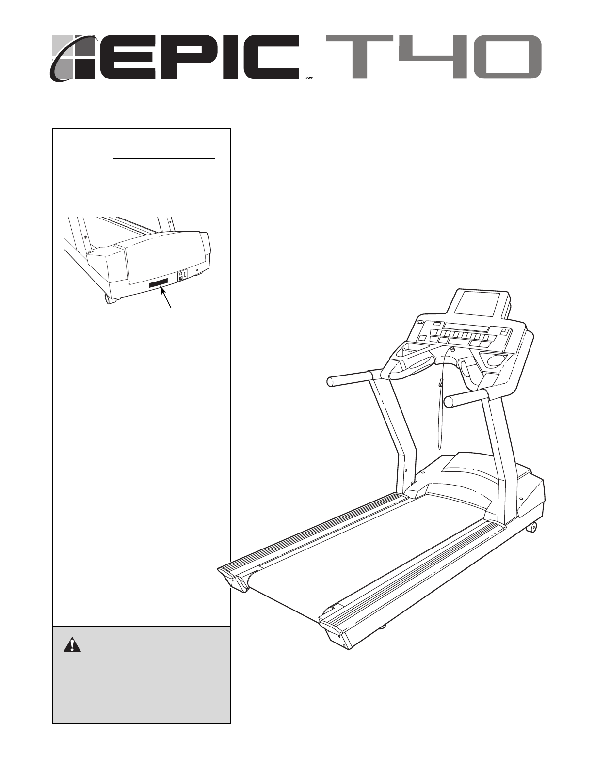
CAUTION
Read all precautions and instructions in this manual before
using this equipment. Keep this
manual for future reference.
Model No. FMTL39940
Serial No.
The serial number is found in the
location shown below. Write the
serial number in the space above.
Serial Number Decal
QUESTIONS?
If you have questions, or if there
are missing parts, we will guarantee complete satisfaction
through direct assistance from
our factory.
TO AVOID UNNECESSARY DELAYS, PLEASE CALL DIRECT TO
OUR TOLL-FREE CUSTOMER
HOT LINE. The trained technicians on our Customer Hot Line
will provide immediate assistance, free of charge to you.
CUSTOMER HOT LINE:
1-800-999-3756
Mon.–Fri., 6 a.m.–6 p.m. MST
USER'S MANUAL

IMPORTANT PRECAUTIONS . . . . . . . . . . . . . . . . . . . . . . . . . . . . . . . . . . . . . . . . . . . . . . . . . . . . . . . . . . . . . . . . .3
BEFORE YOU BEGIN . . . . . . . . . . . . . . . . . . . . . . . . . . . . . . . . . . . . . . . . . . . . . . . . . . . . . . . . . . . . . . . . . . . . . . .6
ASSEMBLY . . . . . . . . . . . . . . . . . . . . . . . . . . . . . . . . . . . . . . . . . . . . . . . . . . . . . . . . . . . . . . . . . . . . . . . . . . . . . . .7
HOW TO USE THE CHEST PULSE SENSOR . . . . . . . . . . . . . . . . . . . . . . . . . . . . . . . . . . . . . . . . . . . . . . . . . . .10
TREADMILL OPERATION . . . . . . . . . . . . . . . . . . . . . . . . . . . . . . . . . . . . . . . . . . . . . . . . . . . . . . . . . . . . . . . . . . .11
TROUBLESHOOTING . . . . . . . . . . . . . . . . . . . . . . . . . . . . . . . . . . . . . . . . . . . . . . . . . . . . . . . . . . . . . . . . . . . . . .27
EXERCISE GUIDELINES . . . . . . . . . . . . . . . . . . . . . . . . . . . . . . . . . . . . . . . . . . . . . . . . . . . . . . . . . . . . . . . . . . .31
PART LIST . . . . . . . . . . . . . . . . . . . . . . . . . . . . . . . . . . . . . . . . . . . . . . . . . . . . . . . . . . . . . . . . . . . . . . . . . . . . . . .32
ORDERING REPLACEMENT PARTS . . . . . . . . . . . . . . . . . . . . . . . . . . . . . . . . . . . . . . . . . . . . . . . . . . . . . . . . . .33
EXPLODED DRAWING . . . . . . . . . . . . . . . . . . . . . . . . . . . . . . . . . . . . . . . . . . . . . . . . . . . . . . . . . . . . . . . . . . . . .34
LIMITED WARRANTY . . . . . . . . . . . . . . . . . . . . . . . . . . . . . . . . . . . . . . . . . . . . . . . . . . . . . . . . . . . . . . .Back Cover
2
EPIC is a trademark of ICON Health & Fitness, Inc.
TABLE OF CONTENTS

1. It is the responsibility of the owner to ensure
that all users of the treadmill are adequately
informed of all warnings and precautions.
2. Use the treadmill only as described in this
manual.
3. Place the treadmill on a level surface, with at
least eight feet of clearance behind it. Do not
place the treadmill on any surface that blocks
air openings. To protect the floor or carpet
from damage, place a mat under the treadmill.
4. Keep the treadmill indoors, away from moisture and dust. Do not place the treadmill in a
garage or covered patio, or near water.
5. Do not operate the treadmill where aerosol
products are used or where oxygen is being
administered.
6. Do not operate the treadmill until it is properly
assembled (see ASSEMBLY on page 7).
7. Inspect and properly tighten all parts of the
treadmill regularly.
8. Keep children under the age of 12 and pets
away from the treadmill at all times.
9. The treadmill should not be used by persons
weighing more than 300 pounds. Do not allow
more than one person on the treadmill at a
time.
10. When connecting the power cord (see page 11),
plug the power cord into a surge suppressor
(not included) and plug the surge suppressor
into a grounded circuit capable of carrying 15
or more amps. No other appliance should be on
the same circuit. Do not use an extension cord.
11. Use only a single-outlet surge suppressor that
meets all of the specifications described on
page 11. To purchase a surge suppressor, see
your local EPIC dealer or call 1-800-806-3651
and order part number 146148.
12. Failure to use a properly functioning surge
suppressor could result in damage to the control system of the treadmill. If the control system is damaged, the walking belt may change
speed or stop unexpectedly, which may result
in a fall and serious injury.
13. Keep the power cord and the surge suppressor away from heated surfaces.
14. Never move the walking belt while the power
is turned off. Do not operate the treadmill if
the power cord or plug is damaged or if the
treadmill is not working properly. (See BEFORE YOU BEGIN on page 6 if the treadmill is
not working properly.)
15. Never start the treadmill while you are standing on the walking belt. Always hold the
handrails while using the treadmill.
16. To protect the treadmill and TV during light-
ning storms, unplug the power cord from the
wall outlet and disconnect the antenna or
cable system. This will prevent damage due
to lightning and power line surges.
17. The pulse sensors are not medical devices.
Various factors, including the user's movement, may affect the accuracy of heart rate
readings. The pulse sensors are intended
only as exercise aids in determining heart
rate trends in general.
18. Never leave the treadmill unattended while it
is running. Always remove the key, unplug
the power cord, and move the on/off switch to
the off position when the treadmill is not in
use.
19. Do not change the incline of the treadmill by
placing objects under it.
WARNING:To reduce the risk of burns, fire, electric shock, or injury to persons, read the
following important precautions and information before operating the treadmill.
3
IMPORTANT PRECAUTIONS

4
20. When using iFIT.com CDs and videos, an
electronic “chirping” sound will alert you
when the speed and/or incline of the treadmill
is about to change. Always listen for the
“chirp” and be prepared for speed and/or incline changes. In some instances, the speed
and/or incline may change before the personal trainer describes the change.
21. When using iFIT.com CDs and videos, you
can manually override the speed and incline
settings at any time by pressing the speed
and incline buttons. However, when the next
“chirp” is heard, the speed and/or incline will
change to the next settings of the CD or video
program.
22. Always remove iFIT.com CDs and videos from
your CD player or VCR when not in use.
23. Never insert or drop any object into any
opening.
24. Make sure to perform all maintenance procedures outlined in this manual. Failure to do so
will void the warranty and may result in damage to the treadmill.
25.
DANGER:Always unplug the power
cord immediately after use, before cleaning
the treadmill, and before performing the maintenance and adjustment procedures described in this manual. Servicing other than
the procedures in this manual should be performed by an authorized service representative only.
26. The treadmill is intended for in-home use
only. Do not use the treadmill in a
commercial, rental, or institutional setting.
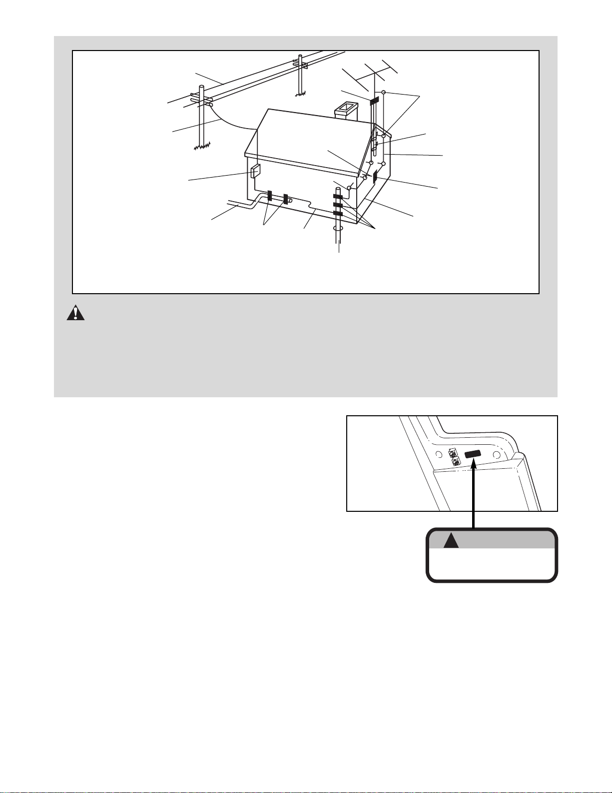
27. If an outside antenna or cable system is con-
nected, be sure that the antenna or cable system is grounded to provide some protection
against voltage surges and built-up static
charges. Section 810 of the National
Electrical Code, ANSI/NFPA No. 70-1984, provides information with respect to proper
grounding of the mast and supporting structure, grounding of the lead-in wire to an antenna discharge unit, size of grounding con-
ductors, location of antenna discharge unit,
connection to grounding electrodes, and requirements for the grounding electrode.
28. An outside antenna system should not be located in the vicinity of overhead power lines
or other electric light or power circuits, or
where it can fall into such power lines or circuits. When installing an outside antenna
system, extreme care should be taken to keep
from touching such power lines or circuits,
as contact with them might be fatal.
29. To reduce the risk of electric shock, do not re-
move the cover or back of the TV. There are
no user serviceable parts inside. Refer servicing to qualified service personnel.
30. Upon completion of any service or repairs to
the treadmill or TV, ask the service technician
to perform safety checks to determine that
the unit is in proper operating condition (see
the drawing on page 5).
• Use No. 10 AWG (5.3mm
2
) copper, No. 8
AWG (8.4mm2) aluminum, No. 17 AWG
(1.0mm
2
) copper-clad steel or bronze wire,
or larger as a ground wire.
• Secure the antenna lead-in and ground
wires to the house with standoff insulators
spaced from 4 to 6 feet (1.22 to 1.83m)
apart.
• Mount the antenna discharge unit as close
as possible to where the lead-in enters the
house.
• Use a jumper wire not smaller than No. 6
AWG (13.3mm
2
) copper or the equivalent
when a separate antenna-grounding electrode is used. See NEC Section 810-21 (j).
Note to CATV system installer: This reminder is
provided to call the CATV system installer’s attention to Article 820-40 of the NEC that provides
guidelines for proper grounding and, in particular, specifies that the cable ground shall be connected to the grounding system of the building,
as close to the point of cable entry as practical.
5
The decal shown at the right is found on the treadmill in
the indicated location. If the decal is missing or illegible,
please call our Customer Service Department toll-free
(see the front cover of this manual) and order a free replacement decal. Apply the decal in the location shown.
Underside
of Console
WARNING:Before beginning this or any exercise program, consult your physician. This
is especially important for persons over the age of 35 or persons with pre-existing health problems.
Read all instructions before using. ICON assumes no responsibility for personal injury or property
damage sustained by or through the use of this product.
SAVE THESE INSTRUCTIONS
Power Lines
Ground
Clamps
Ground
Clamps
Ground
Clamp
Bonding
Jumper
Standoff
Insulators
Antenna
Lead-in Wire
Ground Wire
Ground
Wire
Antenna
Discharge Unit
To External Antenna
Terminal of Treadmill
Mast
Service
Entrance
Equipment
Power Service Grounding
Electrode System (e.g.
Interior Metal Water Pipe)
Service
Entrance
Conductors
Optional Antenna Grounding Electrode Driven 8
Feet (2.44m) Into The Earth (If Required By Local
Codes). See NEC Section 810–21 (f).
!
WARNING
Do not remove or insert this plug while the
safety key is inserted in the console. Touch
metal frame before removing or inserting plug.
Static sensitive components may be affected.
6
Congratulations for selecting the revolutionary EPIC
TM
T40 treadmill. The EPIC T40 treadmill offers an impressive array of features to make your home workouts more effective and enjoyable.
For your benefit, read this manual carefully before
using the treadmill. If you have questions after read-
ing this manual, please call our Customer Service
Department toll-free at 1-800-999-3756, Monday
through Friday, 6 a.m. until 6 p.m. Mountain Time (ex-
cluding holidays). To help us assist you, please note
the product model number and serial number before
calling. The model number of your treadmill is
FMTL39940. The serial number can be found on a
decal attached to the treadmill (see the front cover of
this manual for the location of the decal).
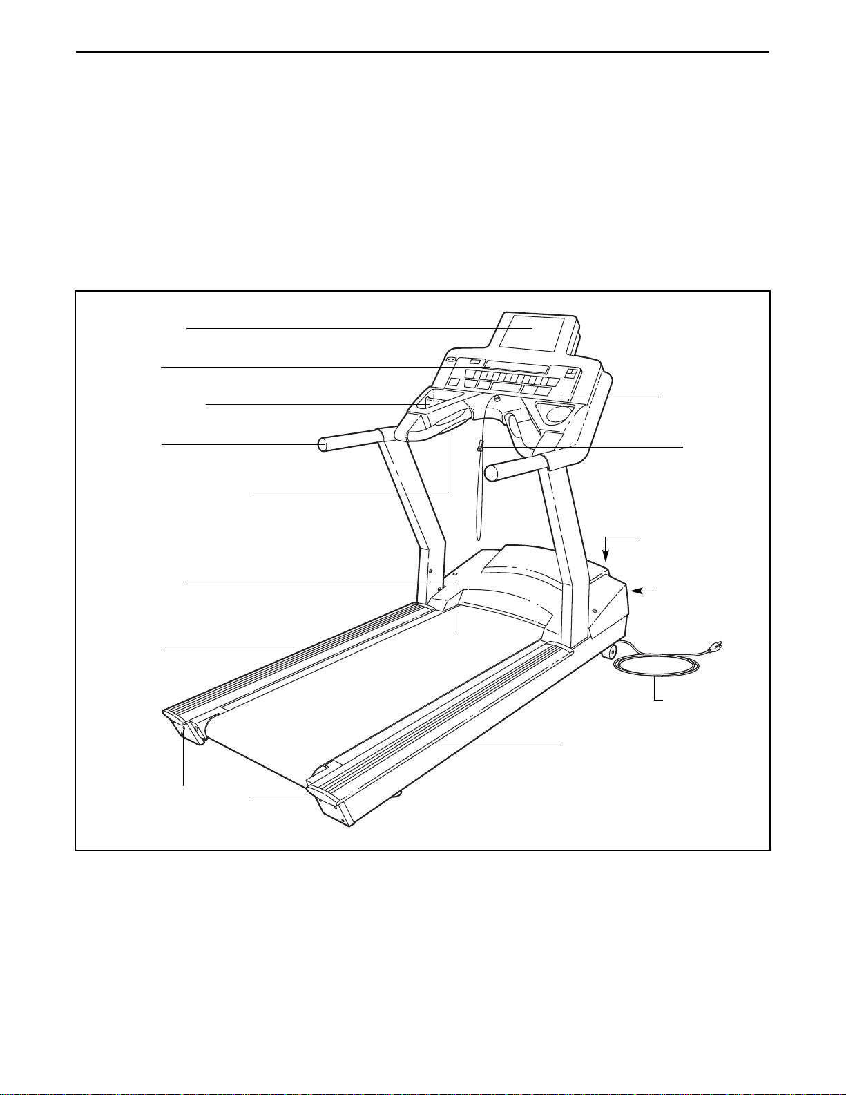
Before reading further, please familiarize yourself with
the parts that are labeled in the drawing below.
BEFORE YOU BEGIN
Handrail
Accessory Tray
Console
Key/Clip
Circuit Breaker
On/off Switch
Walking Belt
Cushioned Walking Platform
Foot Rail
Power Cord
Roller Adjustment Bolts
Water Bottle
Holder
Personal TV
Handgrip Pulse Sensor
7
Assembly requires two persons. Set the treadmill in a cleared area and remove all packing materials. Do not
dispose of the packing materials until assembly is completed. Assembly can be completed using the included
allen wrenches.
Note: The underside of the treadmill walking belt is coated with high-performance lubricant. During shipping, a
small amount of lubricant may be transferred to the top of the walking belt or the shipping carton. This is a normal
condition and does not affect treadmill performance. If there is lubricant on top of the walking belt, simply wipe off
the lubricant with a soft cloth and a mild, non-abrasive cleaner.
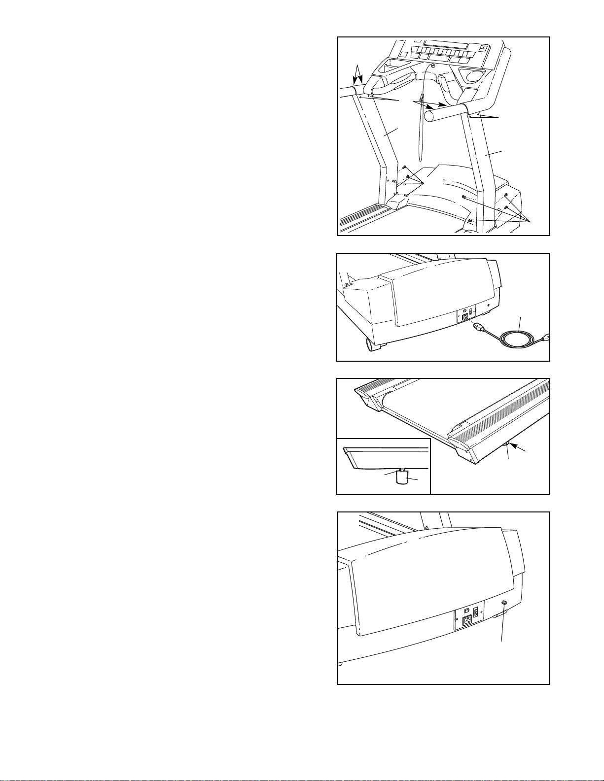
3. Connect the Wire Harness (57) and the TV Cable (133)
in the indicated locations. Push the excess wire and
cable up into the Uprights (95, 97). Make sure that the
Wire Harness and the TV Cable are fully connected.
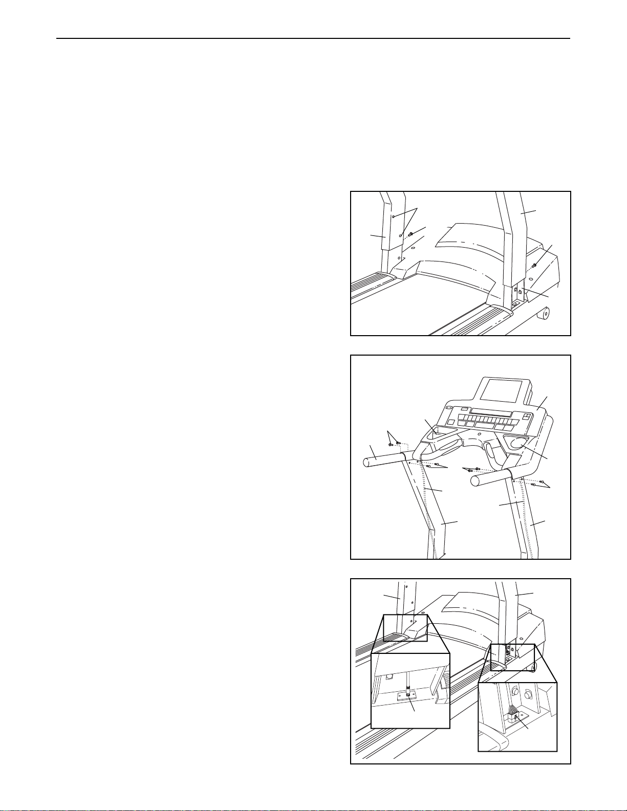
2. Have a second person hold the Handrails (91) near the
Right and Left Uprights (95, 97). Feed the Wire Harness
(57) down into the Right Upright, and feed the TV Cable
(133) down into the Left Upright. Pull the ends of the
Wire Harness and the TV Cable out of the lower ends of
the Uprights. If there are wire ties on the ends of the
Wire Harness and the TV Cable, remove the wire ties.
Set the Handrail on the Uprights.
Finger tighten eight Handrail Bolts (99) into the Uprights
(95, 97) and the Handrail (91). Do not tighten the
Handrail Bolts yet. Be careful to avoid pinching the
Wire Harness (57) and the TV Cable (133).
Note: The CD Holder (86) and the Cup Holder (85) are
replaceable. If these parts become dislodged from the
Console Base (89), simply press them back in.
1. Slide the Right and Left Uprights (95, 97) onto the
brackets near the front of the Frame (76). Make sure
that the Uprights are on the correct sides; the indicated holes must be facing inward.
Raise the Right Upright (95) until the lower hole in the
front of the Right Upright is aligned with the upper hole in
the right bracket on the Frame (76). Thread an Upright
Bolt (96) into the Right Upright and the bracket. Do not
tighten the Upright Bolt yet.
Repeat this step with the Left Upright (97).
ASSEMBLY
95
96
97
Holes
1
97
133
57
91
86
89
85
99
99
99
2
95
57
133
3
95
97
96
76
8
8. Make sure that all parts are properly tightened before you use the treadmill. Keep the included allen
wrenches for adjustment purposes. To protect the floor or carpet from damage, place a mat under the treadmill.
6. After the treadmill is moved to the location where it will
be used (see HOW TO MOVE THE TREADMILL on
page 30), make sure that both Rear Feet (5) and both
front Wheels (not shown) rest firmly on the floor. If the
treadmill rocks slightly, loosen the Rear Foot Locknut
(111) above the right Rear Foot. Turn the right Rear
Foot clockwise or counterclockwise until the rocking
motion is eliminated. Then, tighten the Rear Foot
Locknut.
5
111
6
5. Plug the indicated end of the Power Cord (48) fully into
the treadmill as shown.
48
4. See step 1. While a second person holds the Uprights
(95, 97), remove the two Upright Bolts (96).
Slide the Uprights (95, 97) fully onto the brackets on the
Frame (not shown). Be careful to avoid pinching your
hands or the Wire Harness (not shown). Attach each
Upright with four Upright Bolts (96) as shown. Firmly
tighten all eight Upright Bolts.
Firmly tighten the eight Handrail Bolts (99).
5
111
99
99
99
95
96
96
97
4
7. Note the location of the 75 ohm antenna terminal on
the treadmill. For the television to operate properly,
an antenna, a CATV cable, or a VCR must be connected to the 75 ohm antenna terminal.
If you are using an antenna, it must be properly con-
nected and adjusted for optimal reception. See ANTENNA CONNECTIONS on page 9 to properly connect
an antenna. If you are using a CATV cable, see CATV
CABLE CONNECTION on page 9. If you are using a
VCR, see HOW TO CONNECT A VCR on page 9. The
VCR must be turned on, a videocassette must be properly inserted, and the VCR must be playing. See your
VCR user’s manual for operating instructions.
75 Ohm Antenna
Terminal
5
7
9
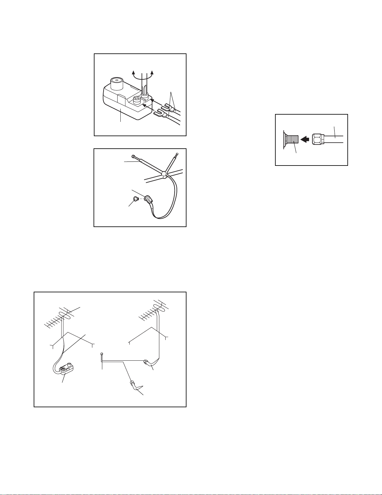
ANTENNA CONNECTIONS
Indoor Antenna
1. Place the VHF
antenna in the
desired location. Connect
the 300 ohm
flat wire on the
antenna to the
screws on the
300 ohm to 75
ohm adapter.
2. Connect the
300 ohm to 75
ohm adapter to
the 75 ohm antenna terminal
on the treadmill
(assembly
drawing 7 on
page 8 shows
the location of
the terminal.)
Outdoor Antenna
Outdoor antennas are subject to weathering that can
reduce signal quality. Inspect the antenna and lead-in
wiring before connecting the antenna. Any service center can explain the various outdoor antennas available.
300 Ohm Flat Wire
1. See the drawing above. Connect the 300 ohm flat
wire to the 300 ohm to 75 ohm adapter.
2. Connect the 300 ohm to 75 ohm adapter to the 75
ohm antenna terminal on the treadmill (see assembly drawing 7 on page 8).
75 Ohm Coaxial Cable
1. See the drawing at the lower left. Connect the 75
ohm coaxial cable directly to the 75 ohm antenna
terminal on the treadmill (see assembly drawing 7
on page 8).
CATV CABLE CONNECTION
1. Connect the CATV
cable (75 ohm coaxial
cable) to the 75 ohm
antenna terminal on
the treadmill (see assembly drawing 7 on
page 8). Route the
cable so it will not be
pinched or crushed by
the wheels when the incline is changed.
Note: A satellite receiver, VCR, or DVD player can
also be connected to the treadmill. Connect a CATV
cable from the coaxial output on your equipment
(usually labeled TV OUT or RF OUT) to the 75 ohm
antenna terminal on the treadmill (see assembly
drawing 7 on page 8). Audio/video equipment without coaxial outputs (some satellite receivers and
DVD players) will require an RF modulator to work
correctly with the treadmill. RF modulators are available at electronics stores. See the owner's manual
for the equipment you wish to connect to determine
if an RF modulator is needed.
HOW TO CONNECT A VCR
Note: A CATV cable (75 ohm coaxial cable) at least
nine feet long is required.
1. Connect one end of the CATV cable to the video
output jack on your VCR.
2. Plug in the power cord of your VCR. See your VCR
user’s manual for proper grounding instructions.
3. Connect the CATV cable to the 75 ohm antenna ter-
minal on the treadmill (see assembly drawing 7 on
page 8).
To operate the television with your VCR, make sure
channel 3 or 4 is selected.
300 to 75 Ohm Adapter
Screwdriver
VHF 300
Ohm Flat
Wire
75 Ohm
Terminal
300 to 75 Ohm
Adapter
VHF Rod
Antenna
Combination
VHF/UHF Antennas
300 Ohm
Flat Wire
75 Ohm
Terminal
on Treadmill
300 to 75
Ohm Adapter
75 Ohm
Coaxial Cable
75 Ohm CATV Cable
VHF 75 Ohm Jack
75 Ohm CATV Cable
10
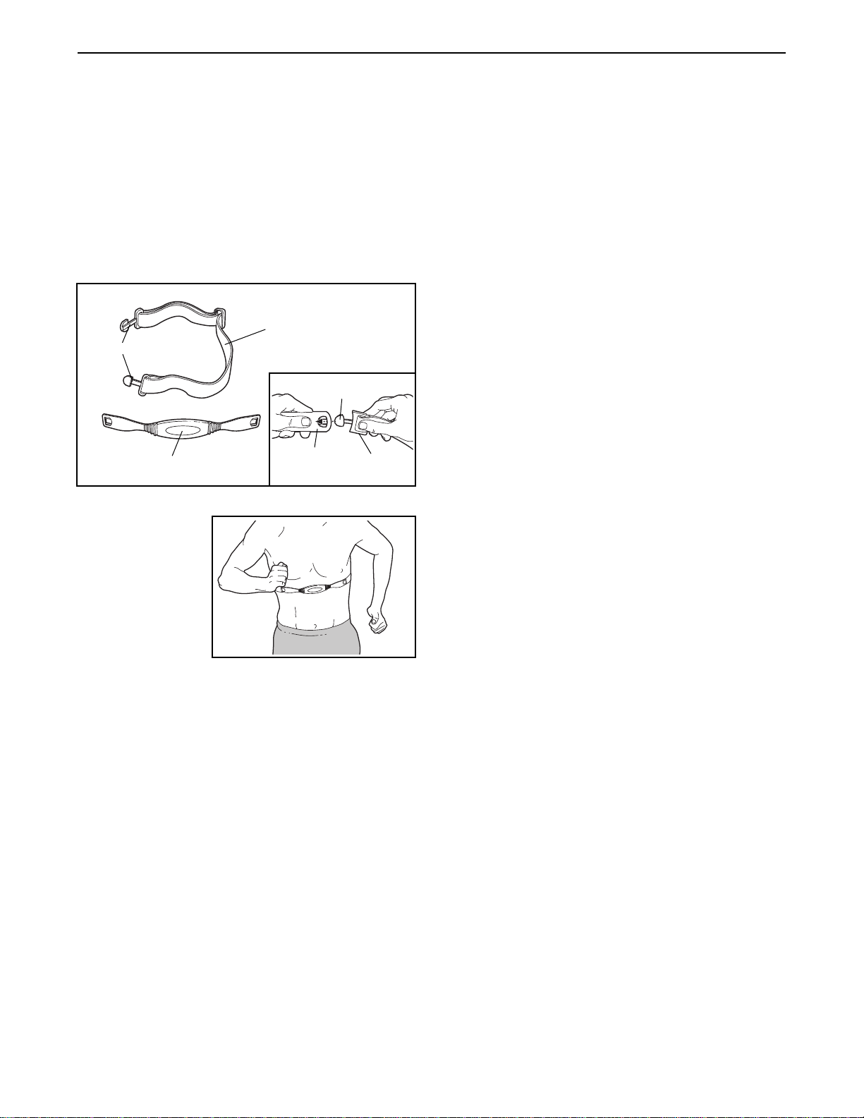
HOW TO PUT ON THE CHEST PULSE SENSOR
The chest pulse sensor consists of two components:
the chest strap and the sensor unit (see the drawing
below). Insert the tab on one end of the chest strap into
one end of the sensor unit, as shown in the inset drawing. Press the end of the sensor unit under the buckle
on the chest strap. The tab should be flush with the
front of the sensor unit.
Next, wrap the
chest pulse sensor around your
chest and attach
the other end of
the chest strap to
the sensor unit.
Adjust the length
of the chest strap,
if necessary. The
chest pulse sensor should be under your clothes, tight
against your skin, and as high under the pectoral muscles or breasts as is comfortable. Make sure the logo
on the sensor unit is facing forward and is right-sideup.
Pull the sensor unit away from your body a few inches
and locate the two electrode areas on the inner side
(the electrode areas are covered by shallow ridges).
Using saline solution such as saliva or contact lens solution, wet both electrode areas. Return the sensor unit
to a position against your chest.
CHEST PULSE SENSOR CARE AND MAINTENANCE
• Thoroughly dry the chest pulse sensor after each
use. The chest pulse sensor is activated when the
electrode areas are wetted and the heart rate
monitor is put on; the chest pulse sensor shuts off
when it is removed and the electrode areas are
dried. If the chest pulse sensor is not dried after
each use, it may remain activated longer than necessary, draining the battery prematurely.
• Store the chest pulse sensor in a warm, dry place.
Do not store the chest pulse sensor in a plastic bag
or other container that may trap moisture.
• Do not expose the chest pulse sensor to direct
sunlight for extended periods of time; do not expose
it to temperatures above 122° Fahrenheit (50°
Celsius) or below 14° Fahrenheit (-10° Celsius).
• Do not excessively bend or stretch the sensor unit
when using or storing the chest pulse sensor.
• Clean the sensor unit using a damp cloth—never
use alcohol, abrasives, or chemicals. The chest
strap may be hand washed and air dried.
CHEST PULSE SENSOR TROUBLESHOOTING
The instructions on the following pages explain
how the chest pulse sensor is used with the console. If the chest pulse sensor does not function
properly, try the steps below.
• Make sure you are wearing the chest pulse sensor
as described at the left. Note: If the chest pulse sensor does not function when positioned as described,
move it slightly lower or higher.
• Use saline solution such as saliva or contact lens
solution to wet the two electrode areas on the
sensor unit. If heart rate readings do not appear until
you begin perspiring, re-wet the electrode areas.
• As you walk or run on the treadmill, position yourself near the center of the walking belt. For the
console to display heart rate readings, the user
must be within arm’s length of the console.
• The chest pulse sensor is designed to work with
people who have normal heart rhythms. Heart rate
reading problems may be caused by medical
conditions such as premature ventricular contractions (pvcs), tachycardia bursts, and arrhythmia.
• The operation of the chest pulse sensor can be
affected by magnetic interference caused by high
power lines or other sources. If it is suspected that
this is a problem, try relocating the treadmill.
• The CR2032 battery in the chest pulse sensor may
need to be replaced (see page 28).
Chest Strap
Tabs
Sensor Unit
Tab
Sensor
Unit
Buckle
HOW TO USE THE CHEST PULSE SENSOR
11
TREADMILL OPERATION
THE PERFORMANT LUBETMWALKING BELT
Your treadmill features a walking belt coated with
PERFORMANT LUBE
TM
, a high-performance lubricant.
IMPORTANT: Never apply silicone spray or other
substances to the walking belt or the walking platform. Such substances will deteriorate the walking
belt and cause excessive wear.
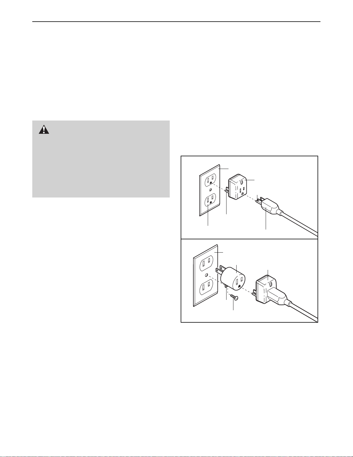
HOW TO PLUG IN THE POWER CORD
Your treadmill, like any other type of sophisticated
electronic equipment, can be seriously damaged by
sudden voltage changes in your home’s power.
Voltage surges, spikes, and noise interference can
result from weather conditions or from other appliances
being turned on or off. To decrease the possibility of
your treadmill being damaged, always use a surge
suppressor with your treadmill (see drawing 1 at
the right). To purchase a surge suppressor, see
your local EPIC dealer or call 1-800-806-3651 and
order part number 146148.
Use only a single-outlet surge suppressor that is
UL 1449 listed as a transient voltage surge suppressor (TVSS). The surge suppressor must have a
UL suppressed voltage rating of 400 volts or less
and a minimum surge dissipation of 450 joules.
The surge suppressor must be electrically rated
for 120 volts AC and 15 amps. There must be a
monitoring light on the surge suppressor to indicate whether it is functioning properly. Failure to
use a properly functioning surge suppressor could
result in damage to the control system of the
treadmill. If the control system is damaged, the
walking belt may change speed or stop unexpectedly, which may result in a fall and serious injury.
This product must be grounded. If it should malfunc-
tion or break down, grounding provides a path of least
resistance for electric current to reduce the risk of electric shock. This product is equipped with a cord having
an equipment-grounding conductor and a grounding
plug. Plug the power cord into a surge suppressor,
and plug the surge suppressor into an appropriate
outlet that is properly installed and grounded in
accordance with all local codes and ordinances.
Important: The treadmill is not compatible with
GFCI-equipped outlets.
This product is for use on a nominal 120-volt circuit,
and has a grounding plug that looks like the plug illustrated in drawing 1 below. A temporary adapter that
looks like the adapter illustrated in drawing 2 may be
used to connect the surge suppressor to a 2-pole
receptacle as shown in drawing 2 if a properly
grounded outlet is not available.
The temporary adapter should be used only until a
properly grounded outlet (drawing 1) can be installed
by a qualified electrician.
The green-colored rigid ear, lug, or the like extending
from the adapter must be connected to a permanent
ground such as a properly grounded outlet box cover.
Whenever the adapter is used it must be held in place
by a metal screw. Some 2-pole receptacle outlet box
covers are not grounded. Contact a qualified electrician to determine if the outlet box cover is
grounded before using an adapter.
DANGER:Improper connection
of the equipment-grounding conductor can
result in an increased risk of electric shock.
Check with a qualified electrician or serviceman if you are in doubt as to whether the
product is properly grounded. Do not modify
the plug provided with the product—if it will
not fit the outlet, have a proper outlet
installed by a qualified electrician.
1
2
Grounded Outlet Box
Grounded Outlet Box
Grounding Plug
Surge Suppressor
Surge Suppressor
Grounding Pin
Adapter
Lug
Metal Screw
Grounded Outlet
Grounding Pin
 Loading...