

Epic Fitness El 2980 Elliptical, El 2980, EPEL69908.1 User Manual
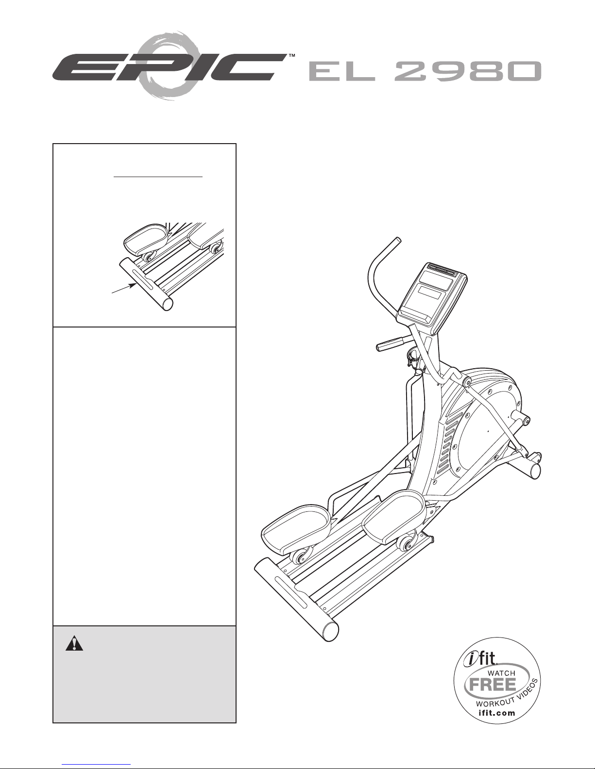
Model No. EPEL69908.1
Serial No.
Write the serial number in the space
above for reference.
Serial
Number
Decal
QUESTIONS?
If you have questions, or if parts are
damaged or missing, DO NOT
CONTACT THE STORE; please
contact Customer Care.
IMPORTANT: Please register this
product (see the limited warranty
on the back cover of this manual)
before contacting Customer Care.
USER'S MANUAL
CALL TOLL-FREE:
1-866-997-6999
Mon.–Fri. 6 a.m.–6 p.m. MT
Sat. 8 a.m.–4 p.m. MT
ON THE WEB:
www.iconservice.com
CAUTION
Read all precautions and instructions in this manual before using
this equipment. Keep this manual
for future reference.
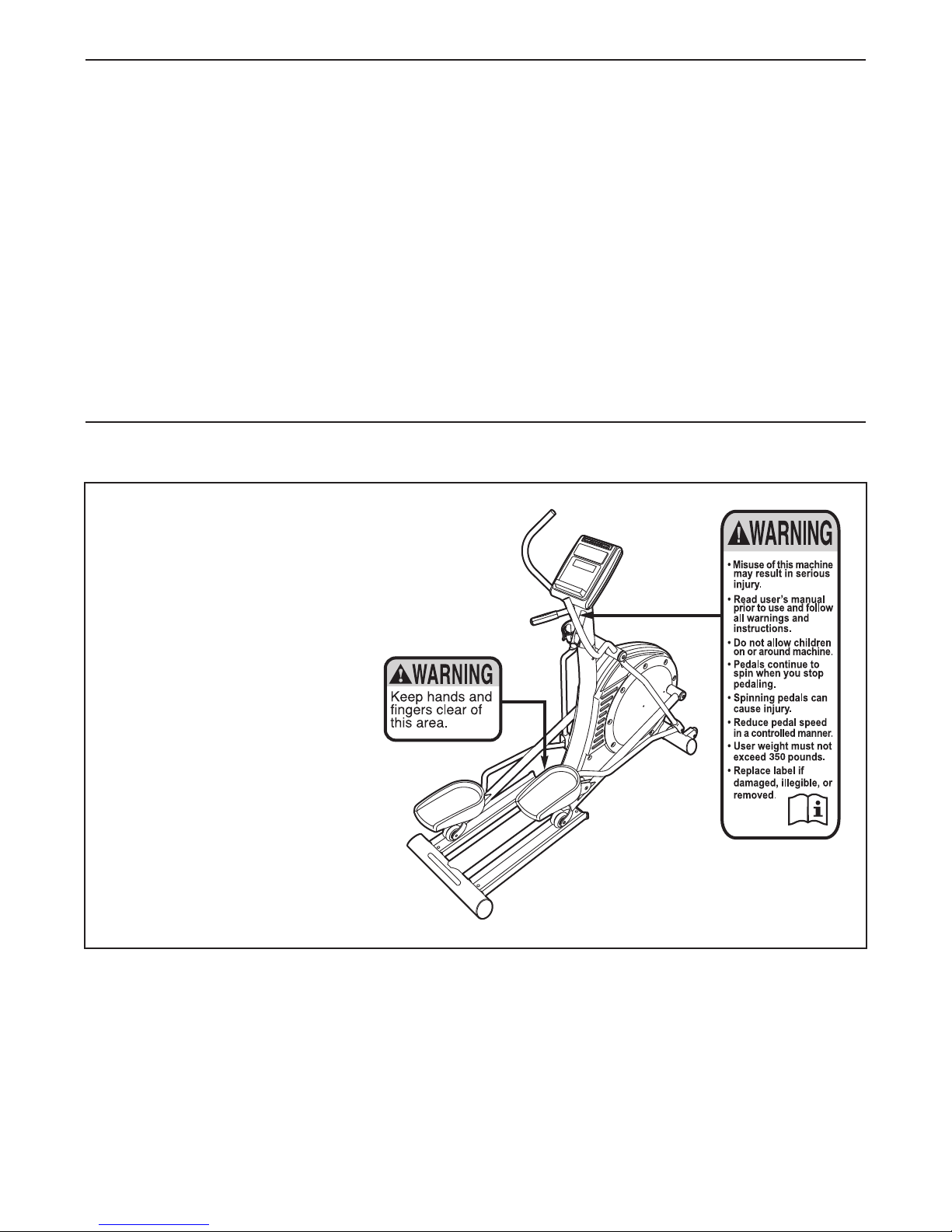
TABLE OF CONTENTS
WARNING DECAL PLACEMENT . . . . . . . . . . . . . . . . . . . . . . . . . . . . . . . . . . . . . . . . . . . . . . . . . . . . . . . . . . . . . .2
IMPORTANT PRECAUTIONS . . . . . . . . . . . . . . . . . . . . . . . . . . . . . . . . . . . . . . . . . . . . . . . . . . . . . . . . . . . . . . . .3
BEFORE YOU BEGIN . . . . . . . . . . . . . . . . . . . . . . . . . . . . . . . . . . . . . . . . . . . . . . . . . . . . . . . . . . . . . . . . . . . . . .4
ASSEMBLY . . . . . . . . . . . . . . . . . . . . . . . . . . . . . . . . . . . . . . . . . . . . . . . . . . . . . . . . . . . . . . . . . . . . . . . . . . . . . . .5
OW TO USE THE ELLIPTICAL . . . . . . . . . . . . . . . . . . . . . . . . . . . . . . . . . . . . . . . . . . . . . . . . . . . . . . . . . . . . .12
H
MAINTENANCE AND TROUBLESHOOTING . . . . . . . . . . . . . . . . . . . . . . . . . . . . . . . . . . . . . . . . . . . . . . . . . . .22
EXERCISE GUIDELINES . . . . . . . . . . . . . . . . . . . . . . . . . . . . . . . . . . . . . . . . . . . . . . . . . . . . . . . . . . . . . . . . . . .23
PART LIST . . . . . . . . . . . . . . . . . . . . . . . . . . . . . . . . . . . . . . . . . . . . . . . . . . . . . . . . . . . . . . . . . . . . . . . . . . . . . .24
EXPLODED DRAWING . . . . . . . . . . . . . . . . . . . . . . . . . . . . . . . . . . . . . . . . . . . . . . . . . . . . . . . . . . . . . . . . . . . .25
ORDERING REPLACEMENT PARTS . . . . . . . . . . . . . . . . . . . . . . . . . . . . . . . . . . . . . . . . . . . . . . . . . .Back Cover
LIMITED WARRANTY . . . . . . . . . . . . . . . . . . . . . . . . . . . . . . . . . . . . . . . . . . . . . . . . . . . . . . . . . . . . . .Back Cover
WARNING DECAL PLACEMENT
This drawing shows the location(s) of the warning
decal(s). If a decal is missing or illegible, see the
front cover of this manual and request a free
replacement decal. Apply the decal in the location
shown. Note: The decal(s) may not be shown at
actual size.
iPod is a trademark of Apple Computer, Inc., registered in the U.S. and other countries. iPod®is not included.
2

IMPORTANT PRECAUTIONS
WARNING: To reduce the risk of serious injury, read all important precautions and
instructions in this manual and all warnings on your elliptical before using your elliptical. ICON
assumes no responsibility for personal injury or property damage sustained by or through the use of
this product.
1. Before beginning any exercise program,
consult your physician. This is especially
important for persons over age 35 or
persons with pre-existing health problems.
2. Use the elliptical only as described in this
manual.
3. It is the responsibility of the owner to ensure
that all users of the elliptical are adequately
informed of all precautions.
4. The elliptical is intended for home use only.
Do not use the elliptical in a commercial,
rental, or institutional setting.
5. Keep the elliptical indoors, away from
moisture and dust. Do not put the elliptical in
a garage or covered patio, or near water.
6. Place the elliptical on a level surface, with at
least 3 ft. (0.9 m) of clearance in the front and
rear of the elliptical and 2 ft. (0.6 m) on each
side. To protect the floor or carpet from damage, place a mat under the elliptical.
9. The elliptical should not be used by persons
weighing more than 350 lbs. (159 kg).
10. Wear appropriate clothes while exercising;
do not wear loose clothes that could become
caught on the elliptical. Always wear athletic
shoes for foot protection while exercising.
11. Hold the handgrip pulse sensors or the
handlebars when mounting, dismounting, or
using the elliptical.
12. The pulse sensor is not a medical device.
Various factors may affect the accuracy of
heart rate readings. The pulse sensor is
intended only as an exercise aid in
determining heart rate trends in general.
13. The elliptical does not have a freewheel; the
pedals will continue to move until the
flywheel stops. Reduce your pedaling speed
in a controlled way.
14. Keep your back straight while using the
elliptical; do not arch your back.
7. Inspect and properly tighten all parts
regularly. Replace any worn parts
immediately.
8. Keep children under age 12 and pets away
from the elliptical at all times.
15. Over exercising may result in serious injury
or death. If you feel faint or if you experience
pain while exercising, stop immediately and
cool down.
3
BEFORE YOU BEGIN
hank you for selecting the revolutionary EPIC
T
2980 elliptical. Cycling is an effective exercise for
increasing cardiovascular fitness, building endurance,
and toning the body. The EL 2980 elliptical provides an
mpressive selection of features designed to make
i
your workouts at home more effective and enjoyable.
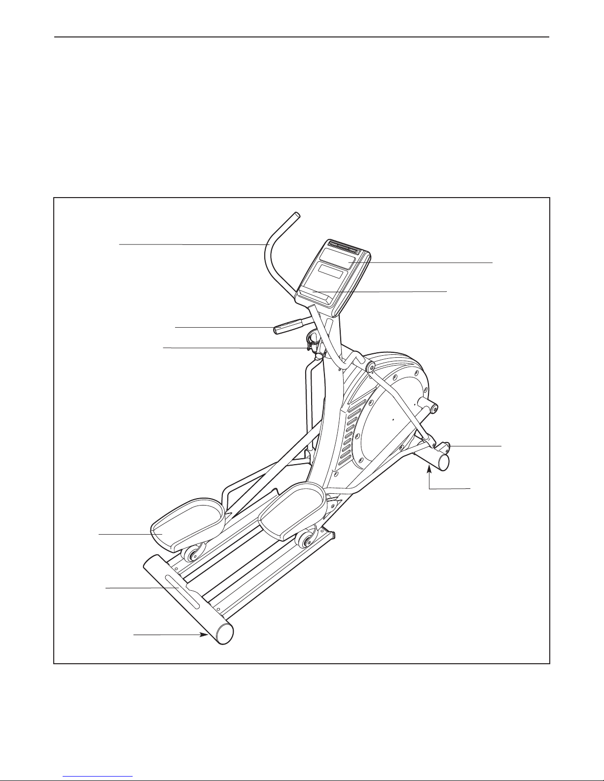
For your benefit, read this manual carefully before
you use the elliptical. If you have questions after
Handlebar
Handgrip Pulse Sensor
Water Bottle Holder*
™
L
E
eading this manual, please see the front cover of this
r
manual. To help us assist you, note the product model
number and serial number before contacting us. The
model number and the location of the serial number
ecal are shown on the front cover of this manual.
d
Before reading further, please familiarize yourself with
the parts that are labeled in the drawing below.
Console
Music Port for iPod
Pedal
Handle
Leveling Foot
Wheel
Leveling Foot
*Water bottle is not included
4
ASSEMBLY
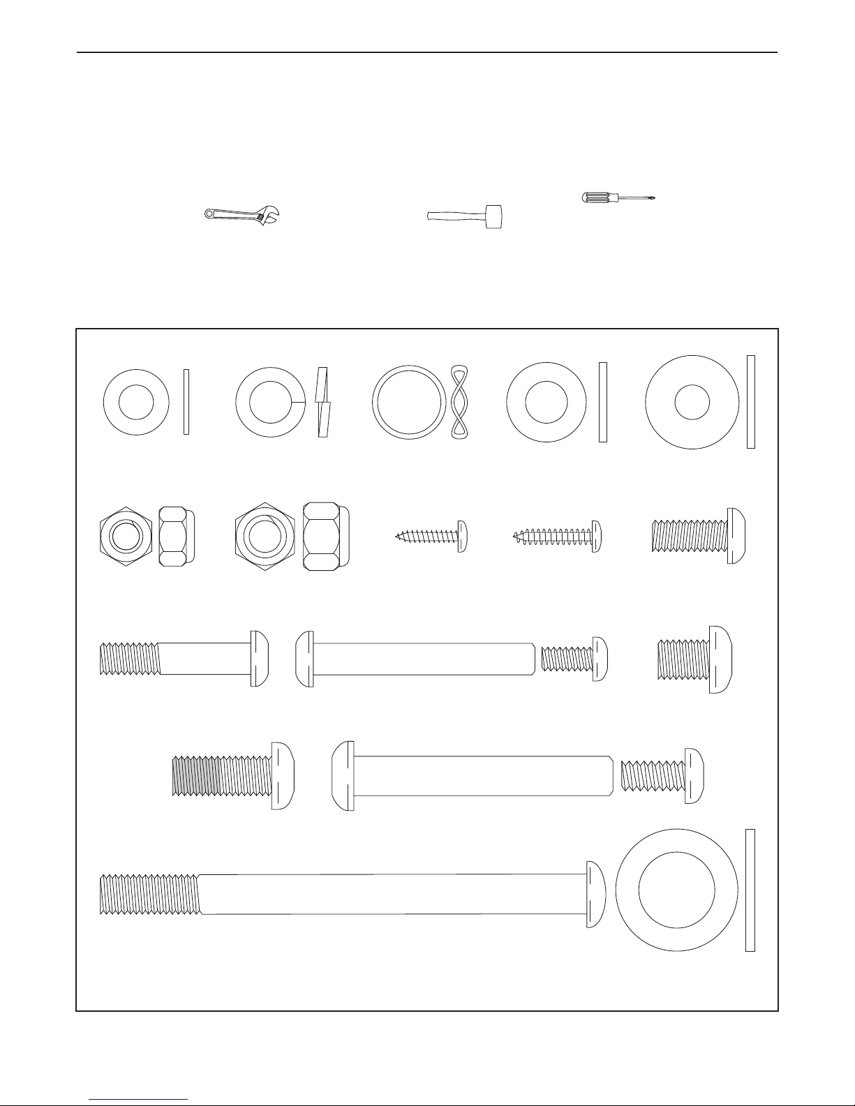
M8 Locknut
(72)–4
M4 x 19mm
Screw (57)–2
M10 Split
Washer (85)–6
M10 Washer
(67)–6
M8 Small
Washer (18)–4
M8 Washer
(69)–4
M8 x 55mm Bolt
Set (82)–2
M10 x 123mm Button Bolt (38)–2
M8 x 38mm Button
Bolt (58)–4
Wave Washer
(78)–4
M10 Locknut
(70)–2
M4 x 16mm
Screw (47)–4
Thrust Washer
(66)–4
M10 x 13mm Button
Screw (54)–6
M10 x 65mm Bolt
Set (80)–2
M8 x 19mm Button
Screw (56)–4
M10 x 25mm Patch
Screw (48)–6
To hire an authorized service technician to assemble the elliptical, call 1-800-445-2480.
ssembly requires two persons. Place all parts of the elliptical in a cleared area and remove the packing mate-
A
rials. Do not dispose of the packing materials until assembly is completed.
In addition to the included tool(s), assembly requires a Phillips screwdriver , an
adjustable wrench , and a rubber mallet .
See the drawings below to identify the small parts needed for assembly. The number in parentheses below each
drawing is the key number of the part, from the PART LIST near the end of this manual. The number following the
key number is the quantity needed for assembly. Note: If a part is not in the hardware kit, check to see if it
has been preassembled. To avoid damaging parts, do not use power tools for assembly.
5
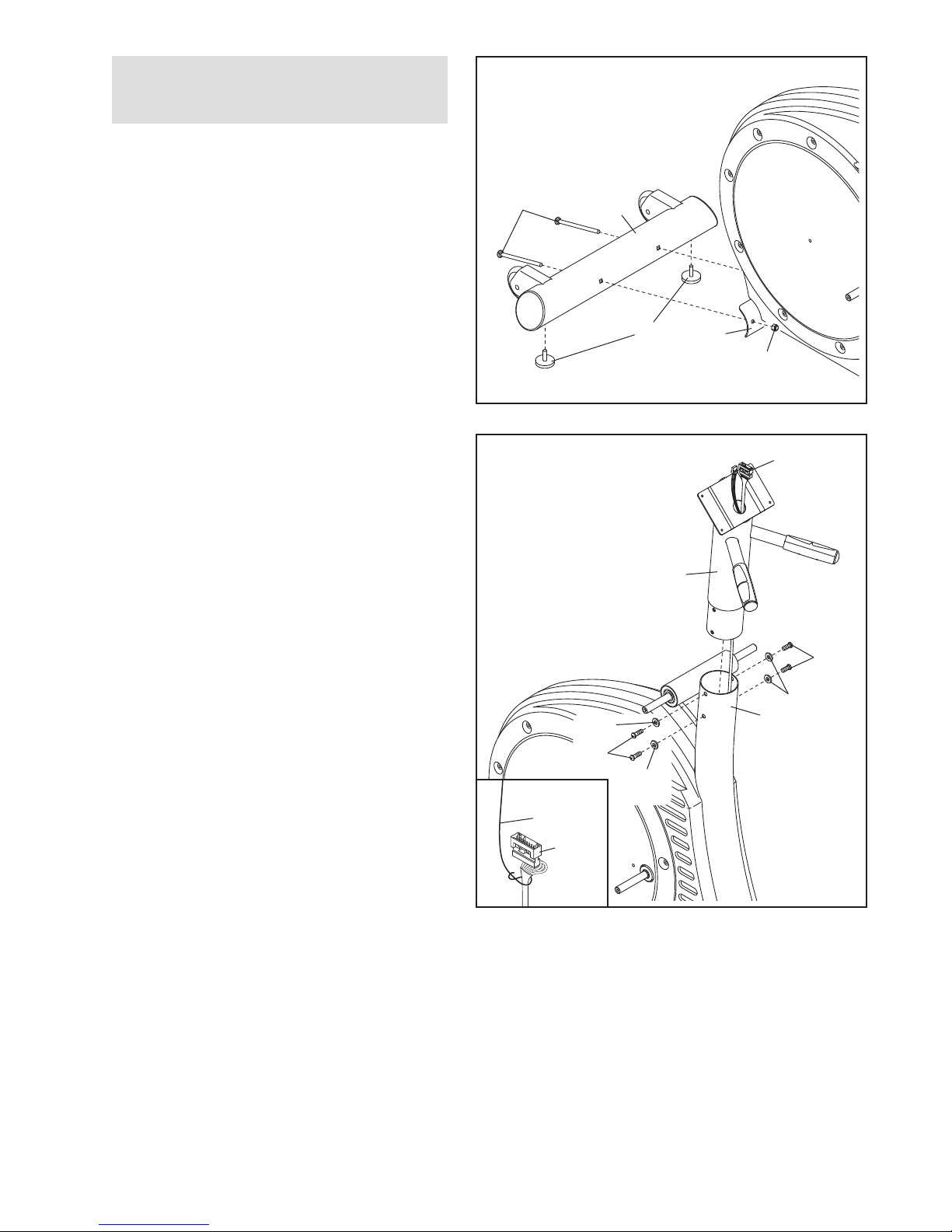
1.
To make assembly easier, read the
nformation on page 5 before you begin.
i
ttach the Stabilizer (8) to the Frame (1) with
A
two M10 x 123mm Button Bolts (38) and two
M10 Locknuts (70) (only one is shown).
Tighten two Leveling Feet (36) into the underside of the Stabilizer (8).
1
8
3
8
2. Have a second person hold the Upright (2) near
the Frame (1) as shown.
See the inset drawing. Locate the wire tie in
the Upright (2). Tie the lower end of the wire tie
to the Wire Harness (77). Next, pull the upper
end of the wire tie upward out of the top of the
Upright. Then, untie and discard the wire tie.
Tip: To prevent the Wire Harness from falling
into the Upright, secure the Wire Harness
with the wire tie.
Tip: Avoid pinching the wires. Insert the
Upright (2) into the Frame (1).
Attach the Upright (2) with four M10 x 25mm
Patch Screws (48) and four M10 Split Washers
(85).
2
Avoid pinching
the wires
85
48
36
85
1
70
77
2
48
85
1
Wire Tie
77
6
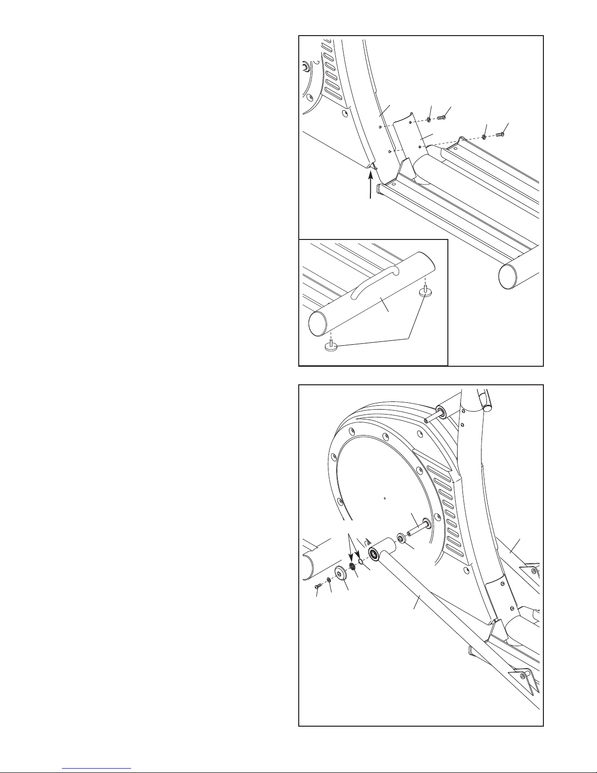
3. Attach the Track Frame (4) to the Frame (1) with
two M10 x 25mm Patch Screws (48) and two
M10 Split Washers (85).
Tip: Finger tighten an M10 x 25mm Patch
crew (48) into the lower hole first, and then
S
finger tighten a Patch Screw into the upper
hole. Then, tighten both Patch Screws.
Tip: This step may be easier if you raise the
Frame (1) a few inches in the location shown
by the arrow at the right while you attach the
Track Frame (4).
See the inset drawing. Tighten two Leveling
Feet (36) into the underside of the Track Frame
(4).
3
1
85
8
4
48
85
4
4
4. Apply a small amount of the included grease to
the sides of two Wave Washers (78) and to two
Thrust Washers (66).
Slide a Weld Spacer (68) onto the left Crank
Arm (37).
Next, identify the Left Track Arm (12), which is
marked with a “Left” sticker.
Orient the Left Track Arm (12) as shown, and
slide it onto the left Crank Arm (37). Then, slide
a Wave Washer (78) on the end of the left Crank
Arm.
Slide an M8 Small Washer (18) and an Axle Cap
(41) onto an M8 x 19mm Button Screw (56).
Next, slide a Thrust Washer (66) onto the shoulder of the Axle Cap.
Then, tighten the M8 x 19mm Button Screw (56)
into the end of the left Crank Arm (37). Make
sure that the Thrust Washer (66) remains on
the shoulder of the Axle Cap (41), and that
the Wave Washer (78) remains on the end of
the left Crank Arm.
36
4
37
Grease
11
68
78
66
41
18
56
12
Repeat this step to attach the Right Track
Arm (11).
7
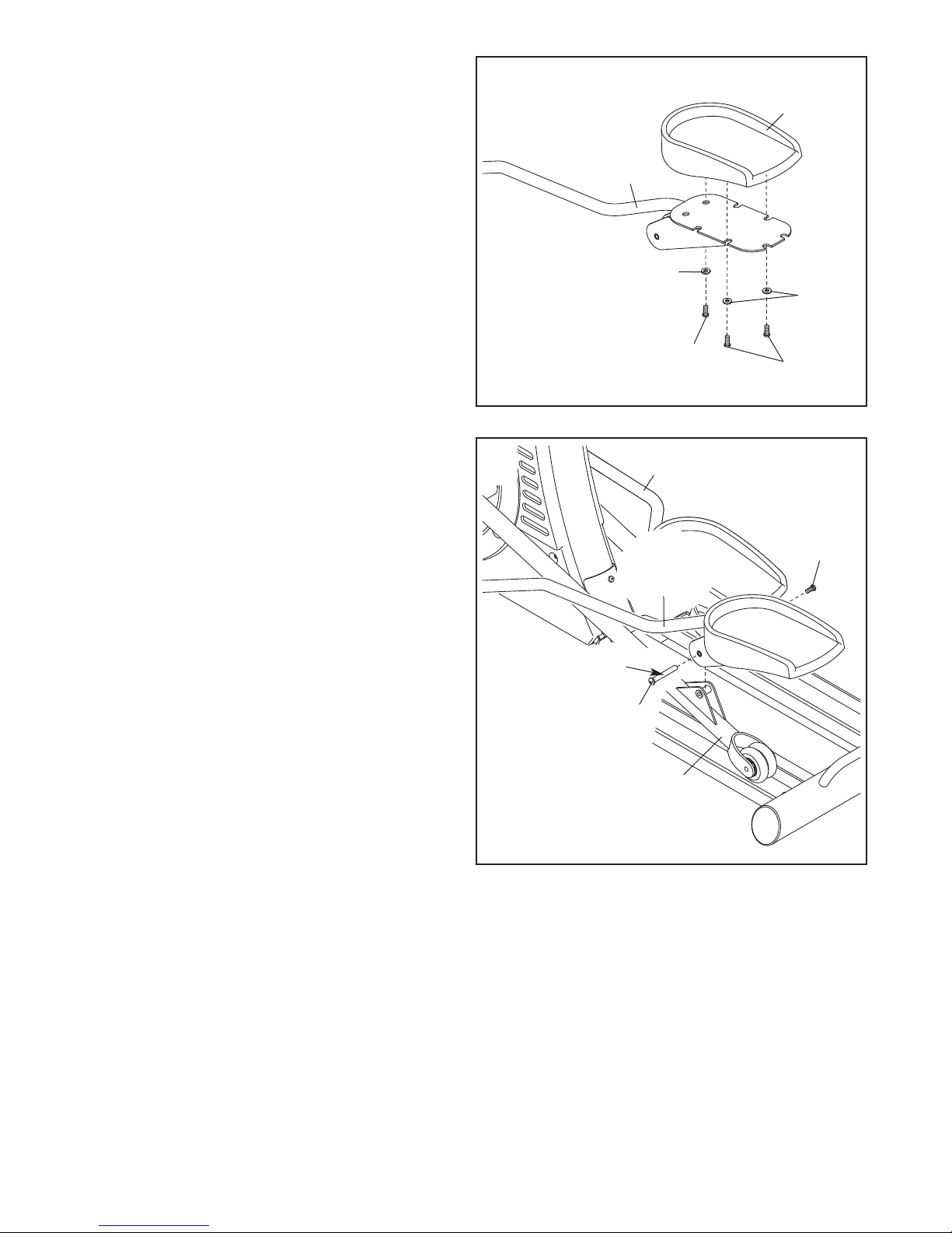
5. Identify the Left Pedal Leg (14), which is marked
with a “Left” sticker.
ttach a Pedal (21) to the Left Pedal Leg (14)
A
with three M10 x 13mm Button Screws (54) and
hree M10 Washers (67). Make sure that the
t
Button Screws are in the indicated holes.
The other holes in the Left Pedal Leg are not
used.
Attach the other Pedal (not shown) to the
Right Pedal Leg (not shown) in the same
way.
5
21
14
67
67
6. Apply grease to the barrel of an M10 x 65mm
Bolt Set (80).
Fit the bracket on the Left Pedal Leg (14) onto
the bracket on the Left Track Arm (12).
Attach the Left Pedal Leg (14) to the Left Track
Arm (12) with the M10 x 65mm Bolt Set (80).
Attach the Right Pedal Leg (13) to the Right
Track Arm (not shown) in the same way.
54
54
6
13
80
14
Grease
80
12
8
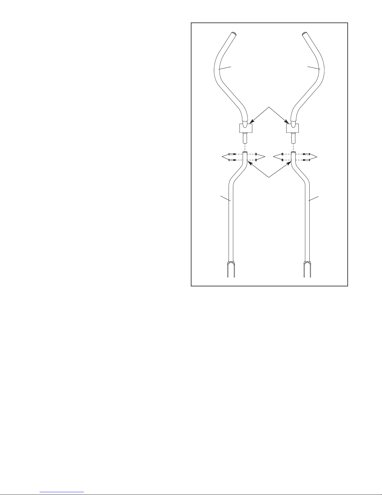
7. Identify the Left Handlebar (19), which is marked
with a “Left” sticker.
nsert the Left Handlebar (19) into one of the
I
Handlebar Legs (17). Next, turn the Left
andlebar and the Handlebar Leg so that the
H
wide side of the pivot tube on the Left
Handlebar is above the hexagonal holes in
the Handlebar Leg.
7
9
1
20
Attach the Left Handlebar (19) with two M8 x
38mm Button Bolts (58) and two M8 Locknuts
(72). Make sure that the Locknuts are inside
the hexagonal holes. Do not tighten the
Button Bolts yet.
Assemble the Right Handlebar (20) and the
other Handlebar Leg (17) in the same way.
58
17
Wide side of
pivot tube
72
Hexagonal
Holes
58
17
9
 Loading...