

Page 1
Page 1 of 2
RFC - RF Cylinder Thermostat
Contents
1. Factory default settings
2. Specication & wiring
3. Mounting
4. Installation
5. Button / symbol description
6. Resetting the thermostat
7. Boost function
8. Lock function
9. To connect the RFC thermostat to the
R_7-RF programmer
10. To disconnect the RFC thermostat from
the R_7-RF programmer
Impor tant: Kee p this document
Prior to setting the thermostat, it is neccessary to complete all required settings described
in this section.
1. Factory default settings
Temperature indicator: °C
Switching dierential: 2.5°C
In built frost protection: 5°C
Keypad lock: O
2. Specications & wiring
Power Supply: 2 x AAA Alkaline Battery
Power consumption: 50 uA
Battery replacement: Once per year
Temp. Control Range: 10...90°C
Dimensions: 84 * 84 * 30mm
Temp. sensor: NTC 10K Ohm @ 25°C - 1.5m probe type
Temp. indication: °C
3a Mounting of temperature sensor
ON CYLINDER: To ensure accurate control of your cylinder, the temperature
sensor should be mounted on the bottom 1/3 of the cylinder. It is essential that
the sensing element is in direct contact with the cylinder and that there is no
insulation between it and the cylinder. 60°C is the temperature level required in
order to prevent the build up of legionella bacteria. The temperature sensor can
be xed to the cylinder using the provided foil tape.
ON PIPEWORK: To ensure accurate control, the temperature sensor should be
mounted on the pipework as tightly as possible. It is essential that the sensing
element is in direct contact with the pipework and that there is no insulation
between it and the pipework. The temperature sensor can be xed to the
pipework using the provided foil tape.
3b Mounting of thermostat
The thermostat should be mounted in a position that will make reading
the display conventient.
The thermostat can be tted to: 1. Recessed conduit boxes
2. Surface mounting boxes
3. Directly on walls
4. Installation
Press the button on the bottom of the thermostat.
The front housing will detach from the baseplate.
Insert the batteries (provided) into the thermostat.
Mount the unit as described in section 3. Ensure the cable sensor is
connected to terminals Con 3 and Con 4.
Oer the baseplate up to the thermostat. Snap it into position to close.
Operating Instructions
CAUTION!
Only qualied electricians or authorised
service sta are permitted to open the
thermostat.
Ensure that this wireless enabled
thermostat is installed 1 metre from any
metalic object, television, radio or wireless
internet transmitter.
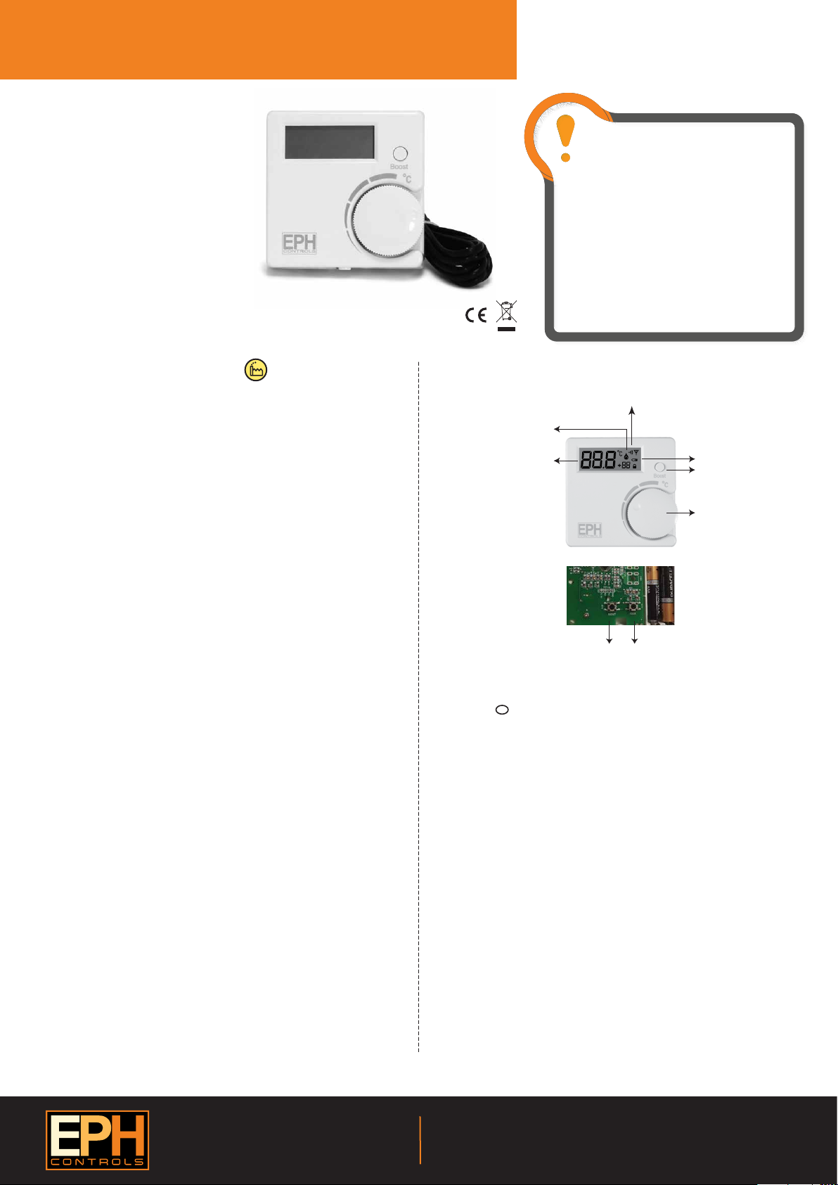
5. Button / symbol description
Wireless symbol
Heating ON symbol
Water temperature
Code buttonReset button
6. Resetting the thermostat
Press the button on the bottom of the thermostat, the front housing
will detach from the baseplate.
Insert the batteries into the thermostat.
Press the reset button on the PCB, ‘NO’ will ash on the screen.
Rotate the hand wheel clockwise until ‘YES’ appears on the screen.
Press the hand wheel once to conrm the setting.
The thermostat has now been reset and the current temperature will
appear on the screen.
7. Boost function
Press the boost button once, twice or three times to boost the heating for
1, 2 or 3 hours respectively. +1H, +2H or +3H will appear on the screen.
The boost function will override the programmer if the programmer is
timed to be O.
8. Lock function
To lock the thermostat, press the hand wheel for 10 seconds. The keypad
symbol will appear on the screen.
To unlock the thermostat, press the hand wheel for 10 seconds. The
keypad symbol will disappear from the screen.
Battery low symbol
Boost button
Set point handwheel
EPH Controls Ireland
Sitecast Industrial Estate, Pouladu,
Cork, T12 W665, Ireland
sales@ephcontrols.com www.ephcontrols.com
20170302_AW1077_RFC-RF_OpIns_JW
EPH Controls UK
Unit E4, Welland Business Park, Valley Way, Market Harborough,
Leicestershire, LE16 7PS, United Kingdom
sales@ephcontrols.co.uk www.ephcontrols.co.uk
Page 2

Page 2 of 2
RFC - RF Cylinder Thermostat
9. To connect the RF thermostat with the programmer
Lower the cover on the front of the timeswitch /
programmer. Move the selector switch to the
RUN position.
On the timeswitch / programmer, press the button for 5 seconds.
Wireless Connect will appear on the screen.
On the RFR wireless room thermostat or RFC wireless cylinder
thermostat, press the Code button. This is located inside the housing
on the Printed Circuit Board.
On the timeswitch / programmer, the available zones will begin to ash.
Press the button for the zone you wish to connect the
thermostat to.
The wireless symbol appears on the screen.
The thermostat will count upwards to the number of the zone that it is
paired with. When it reaches the number of the zone that it is paired
with press the hand wheel on the thermostat.
The timeswitch / programmer is now operating in the wireless mode.
The temperature of the wireless thermostat is now displayed on the
programmer. Repeat this process for the second, third and fourth zone
if required.
CLOCK
SET
RUN
PROG
SET
Operating Instructions
10. To disconnect the RF thermostat with the programmer
Lower the cover on the front of the timeswitch /
programmer. Move the selector switch to the
RUN position.
On the timeswtich/ programmer, press the button for 5 seconds.
This will take you into the Wireless Connect screen.
Press the button for 3 seconds.
This will clear all RF connections thereby disconnecting all thermostats from
the timeswitch / programmer.
Press the button.
CLOCK
SET
RUN
PROG
SET
EPH Controls Ireland
Sitecast Industrial Estate, Pouladu,
Cork, T12 W665, Ireland
sales@ephcontrols.com www.ephcontrols.com
20170302_AW1077_RFC-RF_OpIns_JW
EPH Controls UK
Unit E4, Welland Business Park, Valley Way, Market Harborough,
Leicestershire, LE16 7PS, United Kingdom
sales@ephcontrols.co.uk www.ephcontrols.co.uk
 Loading...