

Page 1
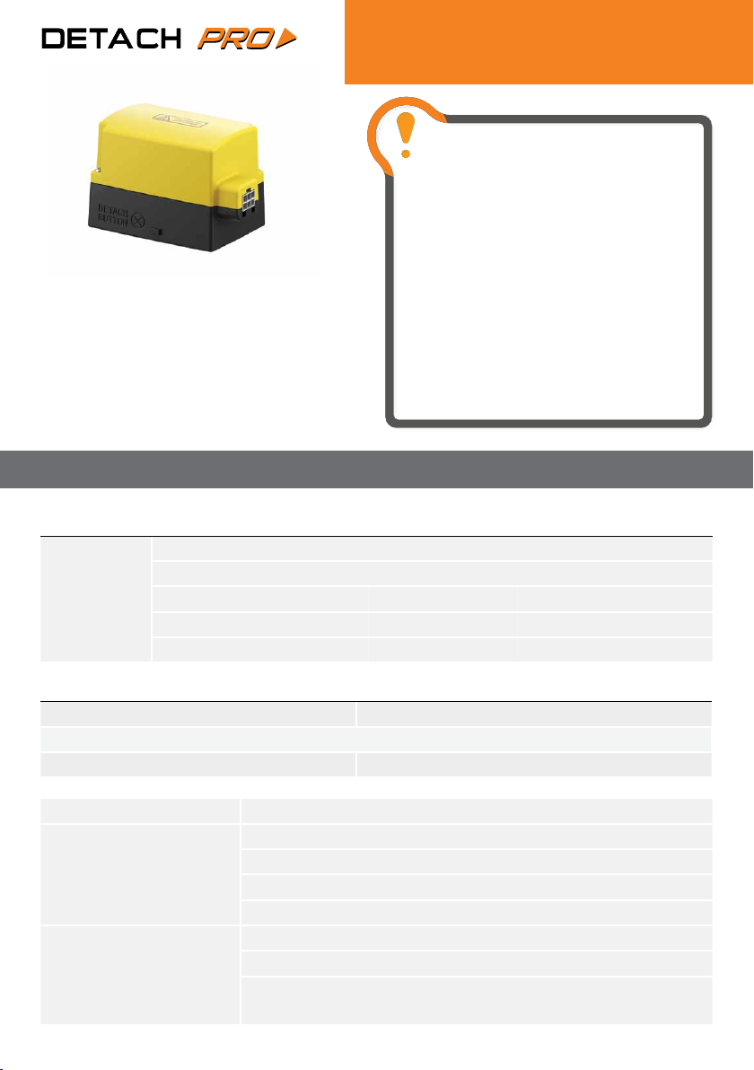
B1PF Actuator
3 Port Motorised Valve Actuator
CAUTION! Installation and connection
should only be carried out by a qualied person
and in accordance with wiring regulations.
Do not open the products. There are no serviceable
or adjustable parts inside. The system must be fused
to no more than 3 Amps.
Important: Keep this document
The B1PF range of actuators c/w auxiliary switch are specically
designed for use in domestic applications only.
They are not designed for use in commercial or industrial
applications such as schools, nursing homes or hotels where large
commercial pump sets are tted.
Warranty will be void If a valve is tted in any application other
than domestic.
Please note we have a full range of commercial and industrial valves
to suit every application.
TECHNICAL SPECIFICATION
ACTUATOR MANUFACTURER MODEL SIZE & TYPE MAX. CLOSE OFF PRESSURE
EPH B322P(F) 22mm Compression 1.0 Bar
B1PF
replacement
for
EPH B328P(F) 28mm Compression 0.6 Bar
Honeywell V4073A 22mm Compression 1.0 Bar
Honeywell V4044C 28mm Compression 0.6 Bar
Horstmann 2322 22mm Compression 1.0 Bar
Isolate mains supply before installation commences.
Isolate mains supply before attaching cable to
actuator.
Isolate mains supply before detaching cable from
actuator.
If this equipment is installed or used in a way not
specied by the manufacturer, its safety may be
impaired.
ACTUATOR
Motor supply voltage 230V Impedance protected motor
Rated impulse voltage 2500V Max. ambient temperature 50˚C
Power consumption 5W Protection rating IP20
LEAD SUPPLIED
ACTUATOR OPERATION
MANUAL OVERRIDE
1.2 metre cable. Earth Connection required.
230V Power to open - Spring return to close.
This is not a fail safe, a no fail or a safety product.
This control is designated Type 1. AA. C in accordance with EN60730.
Type of action is multi position. Type of movement is rotary.
Valve may be manually opened for lling or draining the system.
In normal operation, the lever must be in the Auto position
If the mains power is disconnected, the valve will automatically spring
return to the closed position (Port A)
Page 1
Page 2

INSTALLATION & OPERATING INSTRUCTIONS
1. Valve positioning
Install the valve so the actuator head is not below the horizontal level of the pipework. The open vent and
cold feed must not be isolated. The ow must be in the direction of the arrow. (from the centre port to either
Port A or Port B).
2. Fitting the valve body to the pipework
Fit the valve body using the nuts and olives provided. When tightening the compression nuts ensure that
only the valve body is used for grip. Take care not to overtighten.
3. Removal of actuator from the valve body
To remove the actuator head from the valve body ensure that the manual override lever is in the manual
position. Remove the two screws that x the actuator cover to the base. Remove the actuator cover. Remove
the two screws that x the base to the valve body. Remove the base of the actuator.
4. Fitting of actuator to the valve body
Before tting the actuator, please ensure that the maual override lever is in the raised manual position and
the xing screw is loosened. The actuator is mounted by aligning the 4mm at spindle on the valve body to
the identically sized slot on the actuator. Tighten the two xing screws on the base of the actuator. Fit the
actuator cover and tighten the two screws to hold the cover in place.
Once the valve is tted, place the manual override lever in the raised manual position. It is now possible
to ush and drain the system to remove any foreign matter. The system can now be relled and corrosion
inhibitor may be added if required.
5. Wiring Connections
5.1 The 1.2 metre cable can be connectd as follows:
WIRE COLOUR DESCRIPTION
Blue Neutral supply
Orange
Grey Hot Water OFF from cylinder stat or OFF from programmer
White Central Heating ON from room stat or ON from programmer
Yellow / Green Earth connection
Hot Water ON from cylinder stat or ON from programmer
Also connect to boiler and pump live.
CAUTION!
Ensure that no more than a 3A fuse is used to supply all controls.
It is not permissible to use any voltage other than 230V on the auxiliary switch.
Electrical installation must conform with current I.E.E. regulations.
Page 2
Page 3

5.2 For use as a Diverting Valve, see table below:
ELECTRICAL CONNECTION CABLE CONNECTION VALVE POSITION
Not connected Not connected Hot Water “Port B” open.
230V connected to Orange core Hot Water “Port B” open.
230V connected to Grey core Hot Water “Port B” open.
230V connected to White core Mid position “Port A” and “Port B” open.
230V connected to Grey & White cores Central Heating “Port A” open.
6. Commissioning
Once the system has been lled and vented, ensure the manual override lever is in the auto position.
7. For Hot Water only
Switch the Central Heating ‘OFF” at the programmer or set the room thermostat to the minimum. Switch the
Hot Water “ON” at the programmer and set the cylinder thermostat to the maximum. Port “B” should open on
the valve. The boiler should re and the pump should run. The pipe connected to Port “B” should get hot.
8. For Central Heating only
Switch the Hot Water “OFF” at the programmer or set the cylinder thermostat to the minimum. Switch the
Central Heating “ON” at the programmer and set the room thermostat to the maximum. Port “A” should open
on the valve. The boiler should re and the pump should run. The pipe connected to Port “A” should get hot.
9. For Hot Water and Central Heating
Switch both the Hot Water and the Central Heating “ON” at the programmer. Set both the room thermostat
and the cylinder thermostat to the maximum. The valve should go to the mid position with both Port “A” and
Port “B” open. The boiler should re and the pump should run. The pipes connected to Port “A” and Port “B”
should get hot.
Once satised with the valve operation, reset the programmer and the thermostats to normal control
settings.
WARNING!
Under no circumstances should the actuator be insulated or covered by any other material.
Lack of ventilation will cause the actuator to heat up beyond the maximum permissible ambient temperature
of 50˚C.
Page 3
Page 4

Product Drawing
A
VALVE TYPE A B C
B1PF 70 93 68
B C
WARNING!
Under no circumstances should the actuator be insulated or covered by any other material.
Lack of ventilation will cause the actuator to heat up beyond the maximum permissible ambient temperature of 50˚C.
The crossed out wheelie bin symbol on this product indicates that this product must not be disposed of in your general waste. It can
be taken to your Local Authority Civic Amenity site for free or returned to your retailer for free when you are buying a replacement.
Inappropriate waste handling could lead to negative eects on the environment and human health. With your cooperation you
contribute to the correct disposal, reuse, recycling and recovery of the components of this product and the protection of the
environment.
EPH Controls IE
T 021 434 6238
sales@ephcontrols.com
www.ephcontrols.com
Page 4
EPH Controls UK
T 01933 626 396
sales@ephcontrols.co.uk
www.ephcontrols.co.uk
20170711_AW1077_B1PF_DS_JW
 Loading...