

Page 1
Page 1 of 2
CDT2-24 Room Thermostat Hardwired
Contents
1. Factory default settings
2. Specication & wiring
3. Mounting
4. Installation
5. Wiring diagram
6. Frost protection
7. Button / symbol description
8. Resetting the thermostat
9. Keypad lock and unlock
10. High and Low temperature limitation
11. Adjusting the switching dierential
12. Adjusting the setpoint temperature
Prior to setting the thermostat, it is neccessary to
complete all required settings described in this section.
5. Wiring diagram
1. Factory default settings
Contacts: Volt Free
Temperature indicator: °C
Switching dierential: 0.4°C
In built frost protection: 5°C
High and Low temp. limitation: O
Blue backlight activated : for 10 secs after any button is pressed
Keypad lock: O
Operating Instructions
CAUTION!
Before commencing any work on the electrical
connections, you must rst disconnect the thermostat
from the mains. None of the 24V connections must be live
until the installation has been completed and the housing
is closed. Only qualied electricians or authorised service
sta are permitted to open the thermostat.
There are parts that may carry mains voltage behind the
cover. The thermostat must not be left unsupervised
when open. (Prevent non specialists and especially
children from gaining access to it.)
Impor tant: Kee p this document
INTERNAL WIRING DIAGRAM CDT2-24
If 24Vac output is required, terminals L & 2 must be electrically linked.
321LN
ON OFFCOM
24Vac
SUPPLY
2. Specications & wiring
Power supply: 24Vac 50Hz
Power consumption: 8 VA
Temp. control range: 5 ... 35°C
Ambient temperature: 0 ... 50°C
Contact rating: 7A 24Vac
Dimensions: 84 x 84 x 30mm
Temperature sensor: NTC 10K Ohm @ 25°C
Switching dierential: Adjustable from 0.2/0.4/0.6/0.8/1.0˚C
Frost protection: Only operational in stand by mode
3. Mounting
The mounting height should be 1.5 meters above the oor level.
The thermostat should be wall mounted in the room where the heating is to
be controlled.
The place of installation should be chosen so that the sensor can measure the
room temperature as accurately as possible.
Choose the mounting location to prevent direct exposure to sunlight or other
heating / cooling sources when mounted.
The unit can be tted to: 1. Recessed conduit boxes
2. Surface mounting boxes
3. Directly on walls.
4. Installation
Slacken the fastening screw on the bottom of the thermostat with a philips
head screwdriver.
The thermostat is hinged and can be opened 180 degrees.
Mount the unit as described in section 3.
Wire the thermostat according to the wiring diagram.
Close the thermostat and tighten the fastening screw.
6. Frost protection
Frost protection is built into this thermostat, it is pre xed at 5°C and is not
adjustable.
It will only be activated when the thermostat is in the stand by mode and
the room temperature reaches 5°C.
5°C
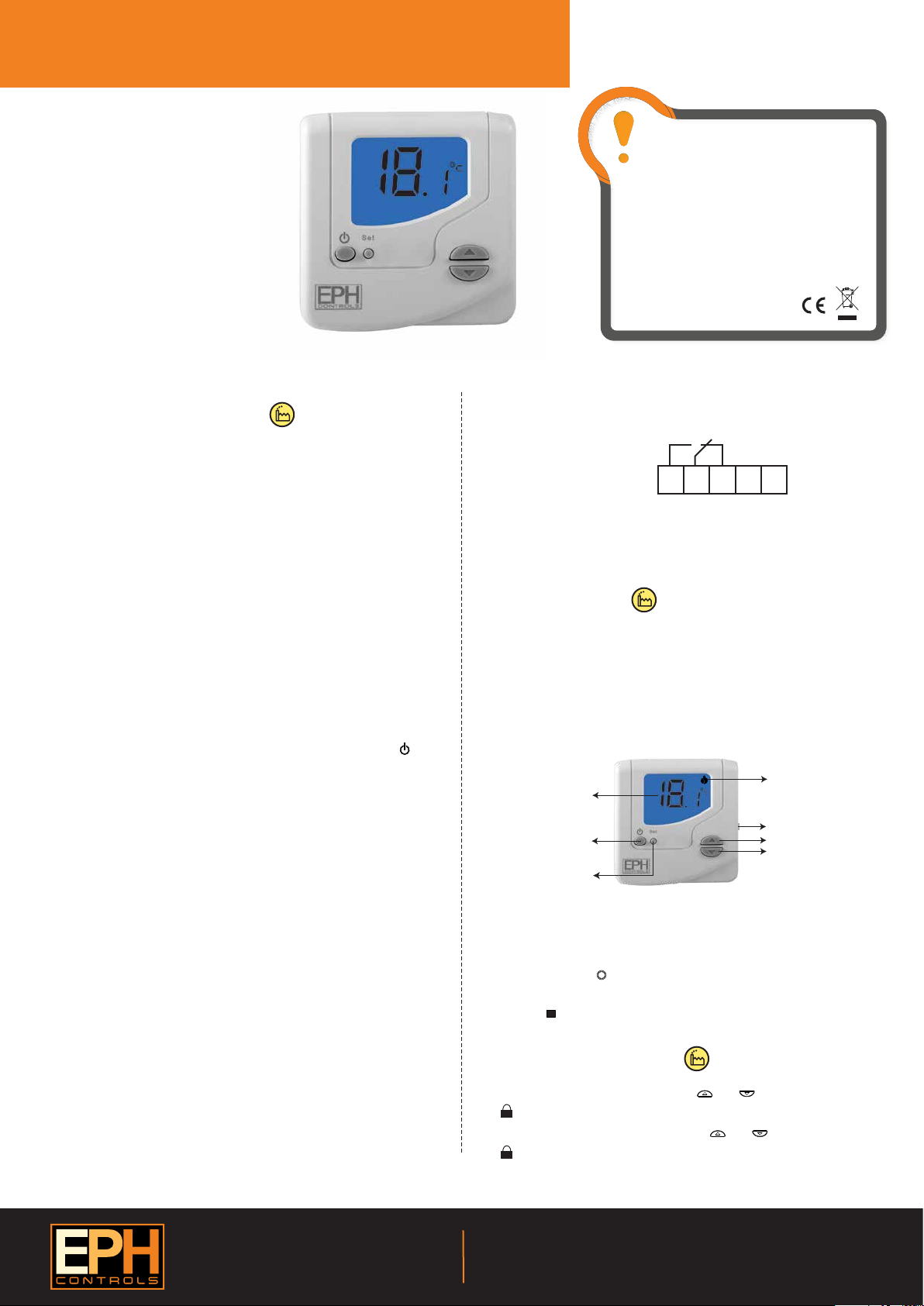
7. Button / Symbol description
Heating ON symbol
Room temperature
Reset button
On / Standby button
Set button
Set point increase
Set point decrease
8. Resetting the thermostat
It is necessary to reset the thermostat prior to initial use.
Press and hold the button for 5 seconds.
dEL will appear on the screen.
Press the button on the side of the thermostat.
9. Keypad lock and unlock
To lock the keypad, press and hold the and buttons for 5 seconds.
will appear on the screen. The keypad is now locked.
To unlock the keypad, press and hold the and buttons for 5 seconds.
will disappear from the screen. The keypad is now unlocked.
Set
RESET
OFF
EPH Controls Ireland
Sitecast Industrial Estate, Pouladu,
Cork, T12 W665, Ireland
sales@ephcontrols.com www.ephcontrols.com
20170308_AW1077_CDT2-24_OpIns_JW
EPH Controls UK
Unit E4, Welland Business Park, Valley Way, Market Harborough,
Leicestershire, LE16 7PS, United Kingdom
sales@ephcontrols.co.uk www.ephcontrols.co.uk
Page 2
Page 2 of 2
CDT2-24 Room Thermostat Hardwired
10. High and Low temperature limitation
An upper and lower temperature limit may be chosen.
Press and hold the and buttons for 10 seconds.
“Limit OFF” will appear on the screen.
Press the button to select “Limit ON” mode.
Press the button to conrm you wish to adjust the high limit temperature.
Press the and buttons to select the high limit temperature.
Press the button to select the low limit temperature mode.
Press the and buttons to select the low limit temperature.
Press the button and the thermostat is ready for operation.
“Limit” will appear on the screen.
To deactivate High and Low temperature limitation.
Press and hold the and buttons for 10 seconds.
“Limit ON” will appear on the screen.
Press the button to deactivate this function.
“Limit OFF” will appear on the screen.
Press the button and the thermostat is ready for operation.
Set
Set
Set
Set
Set
Set
11. Adjusting the switching dierential
Press the button once, Di set will appear on the screen.
The factory default switching dierential of 0.4C will appear on the screen.
Press the and buttons to select the desired dierential from 0.2 - 1˚C.
Press the button to return to normal operation.
Set
Set
OFF
Operating Instructions
12. Adjusting the setpoint temperature
Press the or buttons to adjust the temperature setpoint.
EPH Controls Ireland
Sitecast Industrial Estate, Pouladu,
Cork, T12 W665, Ireland
sales@ephcontrols.com www.ephcontrols.com
20170308_AW1077_CDT2-24_OpIns_JW
EPH Controls UK
Unit E4, Welland Business Park, Valley Way, Market Harborough,
Leicestershire, LE16 7PS, United Kingdom
sales@ephcontrols.co.uk www.ephcontrols.co.uk
 Loading...