

Page 1
Page 1 of 2
R17-RF - 1 Zone RF Timeswitch
Installation Instructions
For use in normal environments.
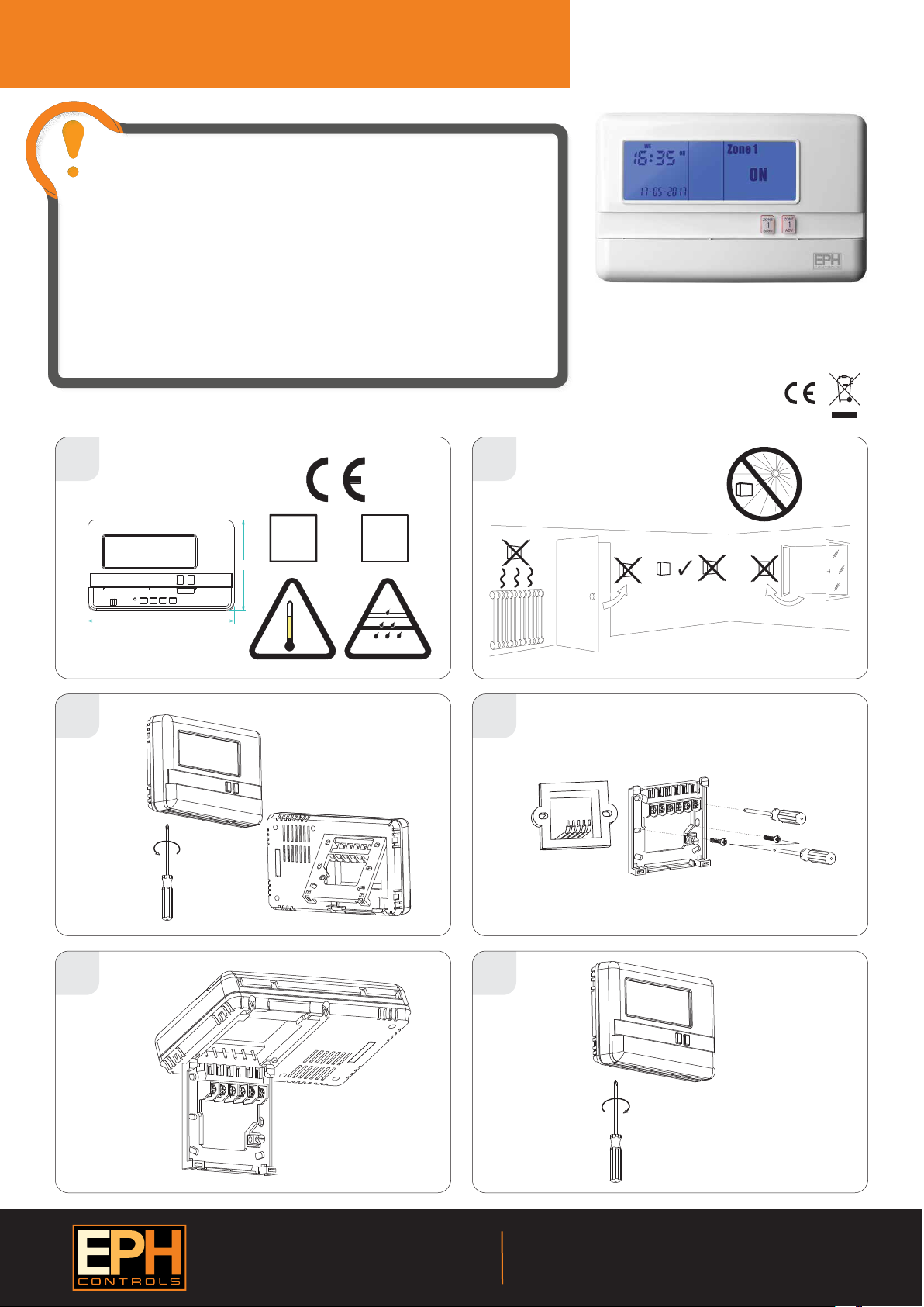
CAUTION! Installation and connection should only be carried out by a qualied
person and in accordance with national wiring regulations.
Before commencing any work on the electrical connections, you must rst disconnect the timeswitch
from the mains. None of the 230V connections must be live until the installation has been completed
and the housing is closed. Only qualied electricians or authorised service sta are permitted to open
the timeswitch. Disconnect from mains supply in the event of any damage to any buttons.
There are parts that carry mains voltage behind the cover. The timeswitch must not be left unsupervised
when open. (Prevent non specialists and especially children from gaining access to it.)
If the timeswitch is used in a way not specied by the manufacturer, its safety may be impaired.
Ensure that this wireless enabled timeswitch is installed 1 metre from any metalic object, television,
radio or wireless internet transmitter.
Prior to setting the timeswitch, it is neccessary to complete all required settings described in this section.
Never remove this product from the electrical baseplate. Do not use sharp tools to push any button.
This timeswitch can be mounted in the following ways: 1. Directly wall mounted 2. Mounted to a recessed conduit box
1
2
This 1 zone RF timeswitch is designed to provide
ON/OFF control for 1 zone, with the value added
application of in built frost protection.
Impor tant: Kee p this document
Type
1C
EN60730
100
160.5
°C
50
122
°F
32
0
3
IP20
EN60529
5-95%RH
4
5 6
EPH Controls Ireland
Sitecast Industrial Estate, Pouladu,
Cork, T12 W665, Ireland
[email protected] www.ephcontrols.com
20170302_AW1077_R17-RF_InsIns_JW
EPH Controls UK
Unit E4, Welland Business Park , Valley Way, Market Harborough,
Leicestershire, LE16 7PS, United Kingdom
[email protected] www.ephcontrols.co.uk
Page 2
Page 2 of 2
R17-RF - 1 Zone RF Timeswitch
Contents
1. Factory default settings
2. Specications & wiring
3. Setting the date & time
4. Frost protection
5. Master reset
1. Factory default settings
Contacts: Volt free contact
Program: 5/2D
Backlight: On
Keypad: Unlocked
Frost Protection: O
Clock type: 24 Hr Clock
Day-Light Saving
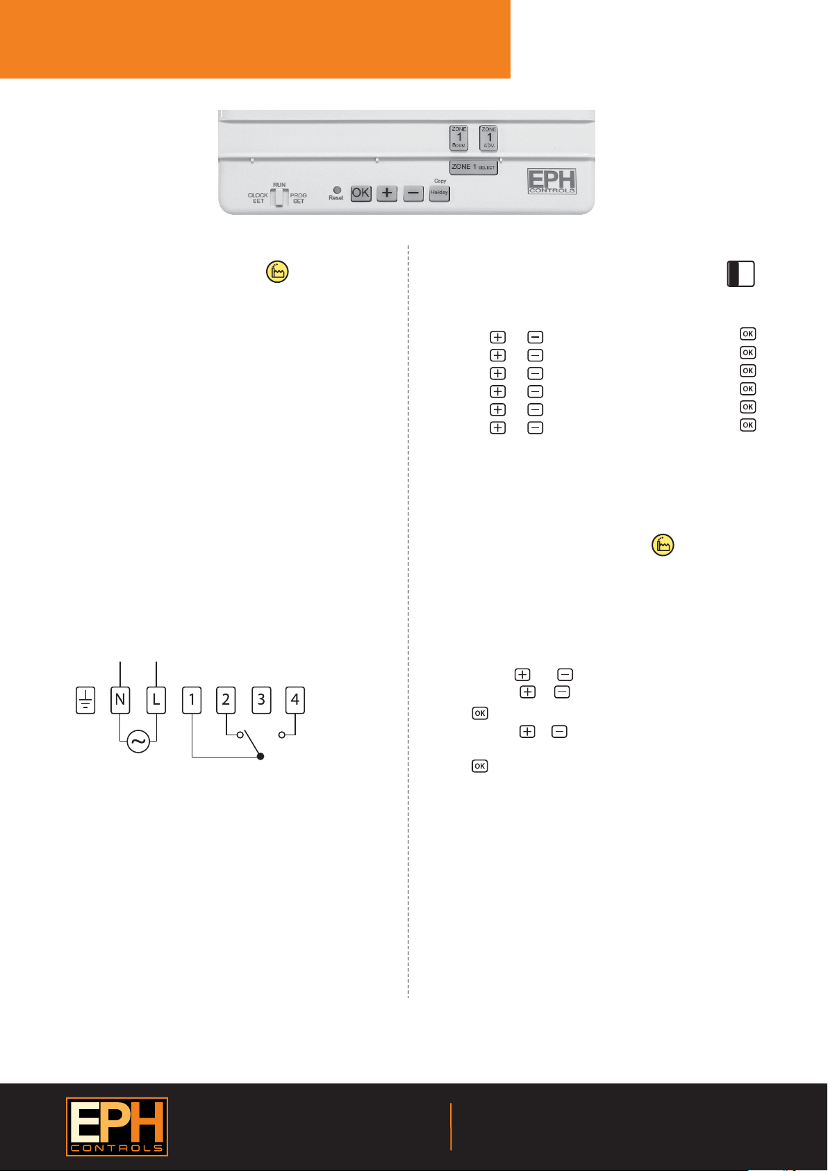
2. Specications & wiring
Power Supply: 230 Vac
Ambient Temp: 0~35°C
Contact Rating: 250 Vac 3A(1A)
Program Memory
backup: 1 year
Battery: 3Vdc Lithium LIR 2032
Backlight: Blue
IP rating: IP20
Backplate: British System Standard
Pollution degree 2: Resistance to voltage surge 2000V
as per EN 60730
Automatic Action: Type 1.S
Software: Class A
200-240Vac
50Hz-60Hz
OFFCOM
CONTACT RATING: 250Vac~/3(1)A
ON
Installation Instructions
For use in normal environments.
RUN
O
CLOCK
SET
Press
Press
Press
Press
Press
Press
3. Setting the date and time
Lower the cover on the front of the timeswitch.
Move the selector switch to the CLOCK SET position.
Press the or buttons to select the day.
Press the or buttons to select the month.
Press the or buttons to select the year.
Press the or buttons to select the hour.
Press the or buttons to select the minute.
Press the or buttons to select 5/2D, 7D or 24H
The date, time and function are now set.
Move the selector switch to the RUN position to run the program, or to
the PROG SET position to change the program setting.
4. Frost protection function
Selectable range 5~20°C
This function is set to protect pipes against freezing or to prevent low room
temperature when the timeswitch is programmed to be OFF or is manually
OFF.
Frost protection can be activated by following the procedure below.
Move the selector switch to the RUN position.
Press both the and buttons for 5 seconds, to enter selection mode.
Press either the or buttons to to turn On or turn O frost protection.
Press button to conrm
Press either the or buttons to increase or decrease the desired frost
protection setpoint.
Press to select.
Zone 1 will be switched ON in the event of room temperature falling below
the frost protection setpoint.
PROG
SET
If mains voltage output is required, terminals L & 1 must be electrically
linked. The cable link is provided with this timeswitch.
EPH Controls Ireland
Sitecast Industrial Estate, Pouladu,
Cork, T12 W665, Ireland
[email protected] www.ephcontrols.com
5. Master reset
Lower the cover on the front of the timeswitch. There are four hinges
holding the cover in place.
Between the 3rd and 4th hinges there is a circular hole. Insert a ball point
pen or similar object to master reset the timeswitch.
After pressing the master reset button, the date and time will now need to
be reprogrammed.
20170302_AW1077_R17-RF_InsIns_JW
EPH Controls UK
Unit E4, Welland Business Park , Valley Way, Market Harborough,
Leicestershire, LE16 7PS, United Kingdom
[email protected] www.ephcontrols.co.uk
 Loading...