

Page 1

User’s Manual
Before using the inverter, you need to read and save the
safety instructions.
Page 2

Page 3

STI SERIES
(STI200, STI300, STI500, STI700, STI1000)
Power Frequency
Pure Sine Wave Inverter
The information presented in this document does
not form part of any quotation or contract, is believed
to be accurate and reliable and may be changed without
notice.
Page 4

CONTENTS
1. Introduction ................................................... 1
2. Important Safety Instructions ........................ 2
3. Inverter Operation ......................................... 4
4. Functions ....................................................... 5
5. Troubleshooting ........................................... 12
6. Maintenance and Warranty .......................... 13
7. Technical Specification ............................... 14
Page 5

1
1. Introduction
Thanks for purchasing STI series inverter. The product is a pure sine
wave power frequency inverter which can convert 12/24/48Vdc to
220/230Vac 50Hz based on full digital and intelligent design. It features
high reliability, high efficiency, concise outline, full protection functions,
easy installation and operation. The inverter can be applied in many fields,
such as household appliances, electric tools and industrial devices etc,
especially for solar photovoltaic power system.
Features:
Complete isolation-type inverter technology, noiseless output.
Adoption of advanced SPWM technology, pure sine wave output.
Dynamic current loop control technology to ensure inverter reliable
operation.
Wide DC input voltage range.
Excellent EMC design.
Low output harmonic distortion(THD≤3%).
LED indicators for input voltage range, load power range, normal
output & failure state.
Optional energy saving mode.
Electronic protect for reverse polarity.
Extensive protections: short-circuit, overload, under/over input
voltage, over-temperature, and inverter‟s inner fault identification
protections.
Wide working temperature range (industrial level).
Continuous operation at full power.
Page 6

2
2. Important Safety Instructions
As an AC power supply equipment, the inverter‟s output voltage is
with the same level as that of household power plug. Mind the AC output
terminals, or you may get an electric shock!
Attentions:
Connect the DC input according to the requirement strictly. The
power inverter has a relatively wide input range, but too high or too
low input may cause problems even destroy the inverter. The surge
input voltage can‟t exceed 18V for the 12V inverters, 36V for 24V
inverters, 72V for 48V inverters, or the inverters will be damaged.
Do not expose the inverter to humid, flammable, explosive or dust
environment.
Keep the inverter out of children touch.
Inverter input is recommended to connect to battery, the min.
capacity of battery(expressed in AH) should be calculated in the
following way: 5times of the rated power of the inverter/battery
voltage. If for testing purpose, user should select DC power supply
current at least twice greater than that of the inverter rated input to
keep inverter normal operation. Use DC power supply for testing
may cause the damage of the inverter.
When the inverter works continuously, its surface may became very
hot, please make sure the air ventilation clearance around the inverter
is more than 10cm. Keep away from the material or device which
may suffer from high temperature when the inverter is working. Do
not install the inverter in airproof location and keep enough space
around the inverter.
The wire connects between battery and inverter should be shorter
Page 7

3
than 3m, the current density should be less than 3.5A/mm2 while the
output of inverter is fully loaded. If the wire longer than 3m, the
current density should be reduced.
A fuse or breaker should be used between battery and inverter, the
value of fuse or switch should be twice of the inverter rated input
current.
Do not connect the battery charger or similar devices to the input
terminal of the inverter.
Do not put the inverter close to the flooded lead-acid battery because
the sparkle in the terminals may ignite the hydrogen released by the
battery.
It‟s an off-grid inverter, if connect to the grid, the inverter may be
damaged.
This inverter can only be used singly, parallel connection or in series
will damage the inverters.
Do not attempt to repair the fault inverter yourself, otherwise it may
lead to a serious accident. Please contact the manufacture‟s engineer.
Page 8

4
3. Inverter Operation
Connect the input and output terminals accurately. Turn on the
power using the ON / OFF switch on the front panel. In order to avoid the
protections resulted from the surge power, please turn on AC loads one by
one after the output of the inverter is normal. Please check it as below:
Set the power switch to the „OFF‟ position.
Insert the load‟s plug into the inverter‟s output outlet.
Connect the battery („+‟ terminal with red line, „-‟with black line). Do
not connect them by contraries, or the power inverter will not work.
Switch the inverter to ON and then turn on the loads one by one.
Check the operation state of both power inverter and loads. „Green‟
of the failure LED indicator means the state is normal.
If there are different loads, it is suggested that turn on the load with
large startup current first, such as television, then turn on the load
such as lamp when the inverter works stable.
If the failure LED indicator is „Red‟ and the buzzer alarms or no
output when you turn on devices, switch off the loads and power
inverter immediately. Check the system by referring to the
troubleshooting guide. Turn on the devices again according to the
operation methods after the failure is removed.
Page 9
5
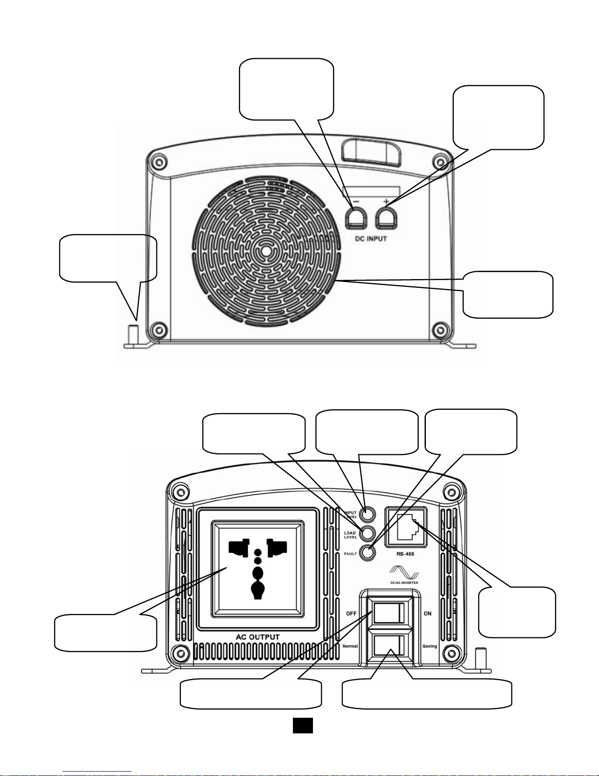
4. Functions
DC Input Panel
AC Output Panel
Protective
Grounding
Fan
Ventilatio
DC Input
Terminal
Negative
DC Input
Terminal
Positive
Fault
Indicator
AC Outlet
ON/OFF Switch
Saving Mode Switch
RS485
Port
Input Level
Indicator
Load Level
Page 10
6
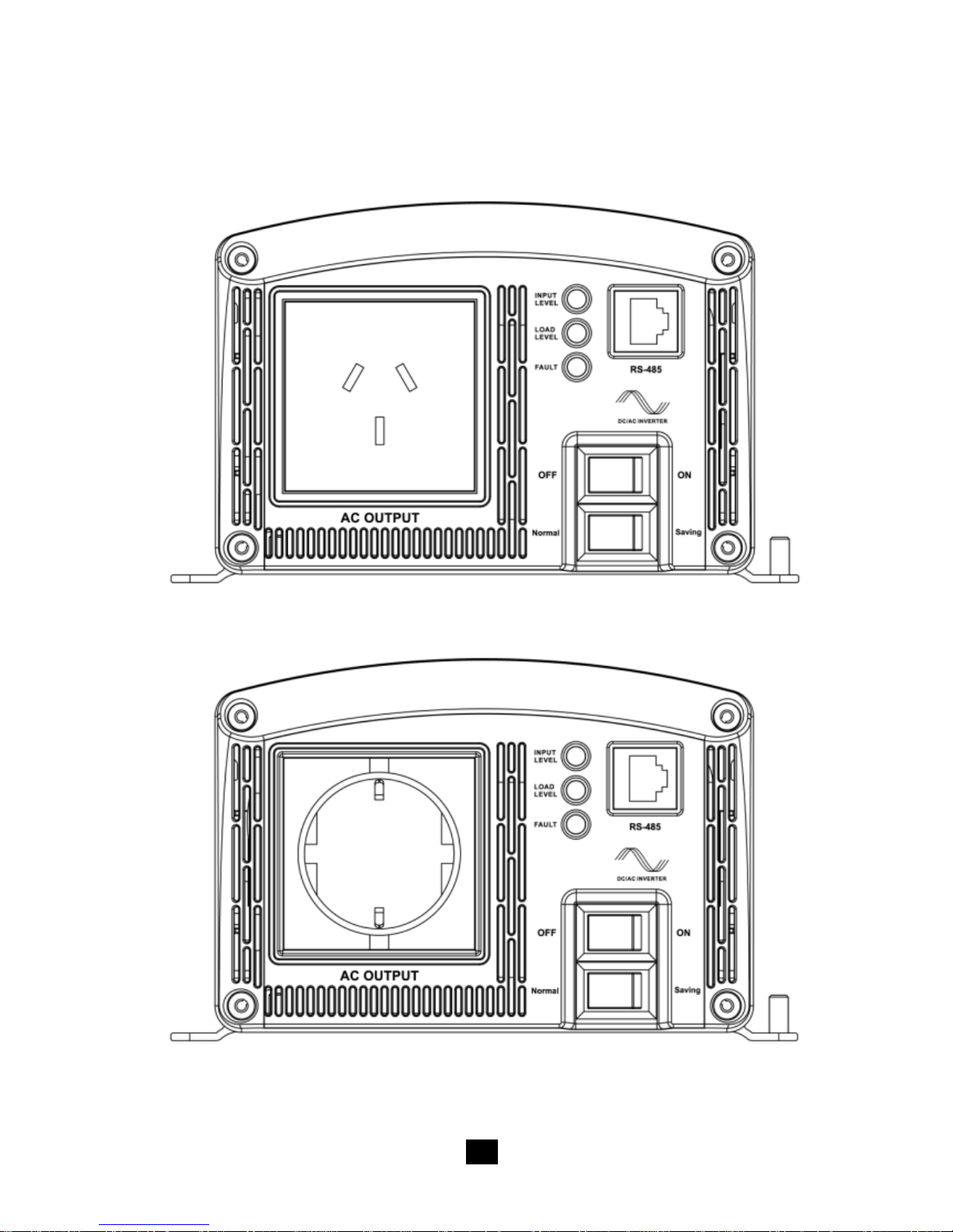
The Optional Outlet
Australia/New Zealand
European
Page 11
7
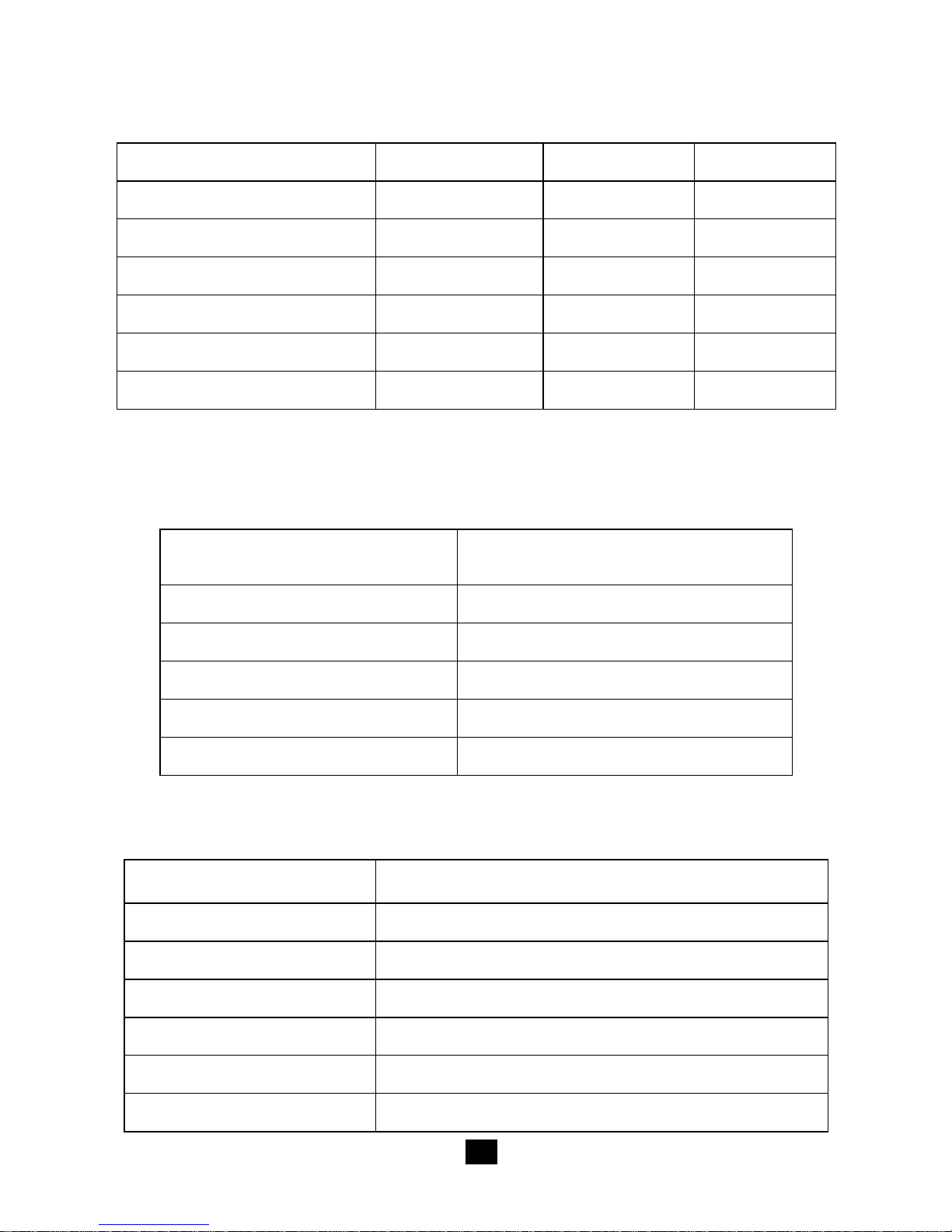
Input Level: Display Input Voltages
LED Status
12V
24V
48V
RED Slow Blink
<10.5
<21
<42
RED
10.5~11
21~22
42~44
ORANGE
11~12
22~24
44~48
GREEN
12~14.5
24~29
48~58
ORANGE Fast Blink
14.5~16
29~32
58~64
RED Fast Blink
>16
>32
>64
Load Level: Display AC Loads
LED Status
AC Load
ORANGE
<20%
GREEN
20%~75%
RED
>75%
RED Slow Blink
Overload
RED Fast Blink
Short Circuit
Output & Fault Status
LED Status
Status
GREEN
Output Normal
RED Fast Blink
Overload or Short circuit, No Output
RED Slow Blink
Over or Low input voltage, No Output
ORANGE Fast Blink
Over temperature, No Output
RED
Inverter Fault, No Output
OFF
Power Off,No Output
Page 12
8
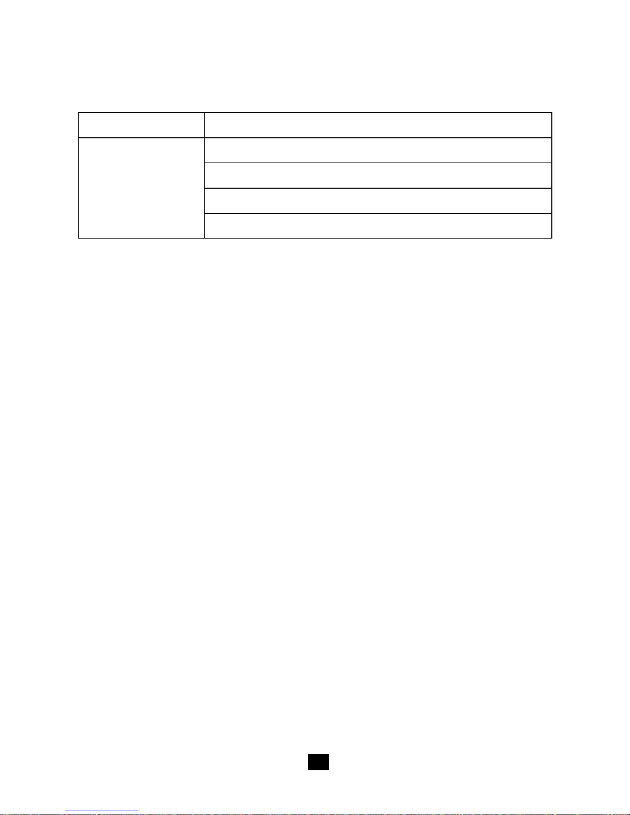
Alarms
Alarms
Status
Buzzer Sounds
Overload or Short circuit, No Output
Over or Low input voltage, No Output
Over temperature, No Output
Inverter Fault, No Output
The buzzer stops after 15S.
Page 13
9
Protections
Output Short Circuit Protection
The inverter switches off the output immediately when the
connecting load is short. Then it recovers the output automatically
after delaying 5 seconds for the first time, 10 seconds for the second
time, and 15 seconds for the third time. If the short circuit status still
remains when the inverter tries to recover for 3 times, you should
clear the load faults then restart the inverter manually.
Overload Protection
Overload
Character
125%
150%
200%
>230%
Continuance
60S
10S
1.5S
<0.2S
Recover 3 times
5 seconds for the first time, 10 seconds for the
second time, and 15 seconds for the third time
If the overload status still remains when the inverter tries to
recover for 3 times, you should reduce the loads then restart the
inverter manually.
Input Low Voltage Protection
The output is switched off when the input voltage is lower than
low voltage protect value, and the output is auto-switched on when
the input voltage reach low voltage recover value. User can also
manually restart the inverter to switch on output by the „ON/OFF
Page 14
10
switch‟, when the input voltage is higher than low voltage protect
value.
12V
24V
48V
Low Voltage
Protect Value
10.5
21
42
Low Voltage
Recover Value
13
26
52
Input Over Voltage Protection
The output is switched off when the input voltage is higher than
over voltage shut off value, also the output is auto-switched on when
the input voltage drops below over voltage recover value.
12V
24V
48V
Over Voltage Shut
Off Value
16
32
64
Over Voltage
Recover Value
15
30
60
Fault Protection
The inverter will shut down when the output voltage is error or
when the inverter has inner fault.
Page 15

11
Over Temperature Protection
The inverter will shut off when the internal temperature is
overheating. And it automatic restarts when the temperature recovers
to the normal level.
Electronic Protect for Reverse Polarity
The Electronic circuit works to protect the inverter from
damage while input reverse polarity. And the inverter will get right
while the input is right.
Others
Saving Mode
When the switch is on “Saving” side, the inverter will enter into
the Saving Mode. It will shut off the output if the loads value is less
than 20VA. Then restart and detect the power of the load again after
10s. If the load is more than 20VA, the inverter will turn on the
output .Otherwise it will shut off output again. It cycles like this. So
please don‟t use the saving mode if the load is smaller than 20VA.
Page 16
12
5. Troubleshooting
WARNING:
High voltage is inside the inverter, do not open or disassemble
it! Attempting to service the unit yourself may cause the risk of
electrical shock or fire!
Problem
Possible Cause
Solution
Input LED
blink, fault red
LED slow blink
Input voltage is
too high or too low
Measure the input voltage. The
inverter recovers when the
input becomes normal.
Load LED
blink, fault red
LED fast blink
Overload or load
short
Check out if the AC load is
within the rated power or
whether there is load short.
Fault orange
LED fast blink
Over temperature
inside the inverter
Improve the quality of
ventilation and do not block
the vents. Restart the inverter
when it is cool down.
Fault red LED
Inverter
abnormal
Remove all the connected
plugs then restart. If inverter
works well, please check the
load and line. If the LED
keeps red, the inverter has
inside faults and should be
returned to the factory
Page 17

13
6. Maintenance and Warranty
The casing of the inverters may be cleaned regularly with a damp
cloth (not wet) to prevent accumulation of dust and dirt. The screws on
the DC input terminals must be tightened.
The warranty period of the inverter is 2 year since the date of
original shipping. Within the period, we will repair the products for free.
Return the defective with shipping cost prepaid. And provide proof of
purchasing date. We will pay the return shipping charges within warranty
period.
The warranty doesn‟t apply under the following conditions:
1. Damaged by accident, negligence, abuse, improper use
2. Input voltage exceed the nominal input voltage of inverter
3. Unauthorized modification or attempted repair
Page 18
14
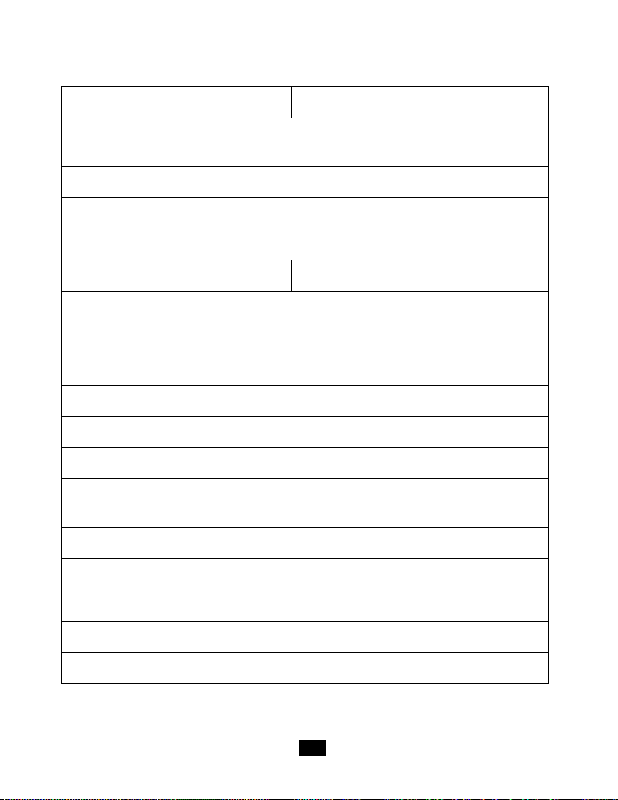
7. Technical Specification
Technical Data
Types
STI200-12-220
STI200-12-230
STI200-24-220
STI200-24-230
Nominal Battery
Voltage
12V
24V
Input Voltage Range
10.5 ~16Vdc
21 ~32Vdc
No Load Consumption
≤4W
≤5W
Output Wave
Pure Sine Wave
Output Voltage
220Vac±3%
230Vac±3%
220Vac±3%
230Vac±3%
Continuous Power
200VA
Power 10 sec
300VA
Power 1.5 sec
400VA
Surge Power
640VA
Frequency
50Hz±0.2%
Distortion THD
≤ 3%( resistive load)
≤ 2%( resistive load)
Efficiency at Rated
Power
≥81%
≥85%
Max. Efficiency
≥88%
≥89%
Dimensions
314.5×166×100.8mm
Installation
200×154mm
Hole Size
Φ8mm
Net Weight
4.5kg
Page 19
15
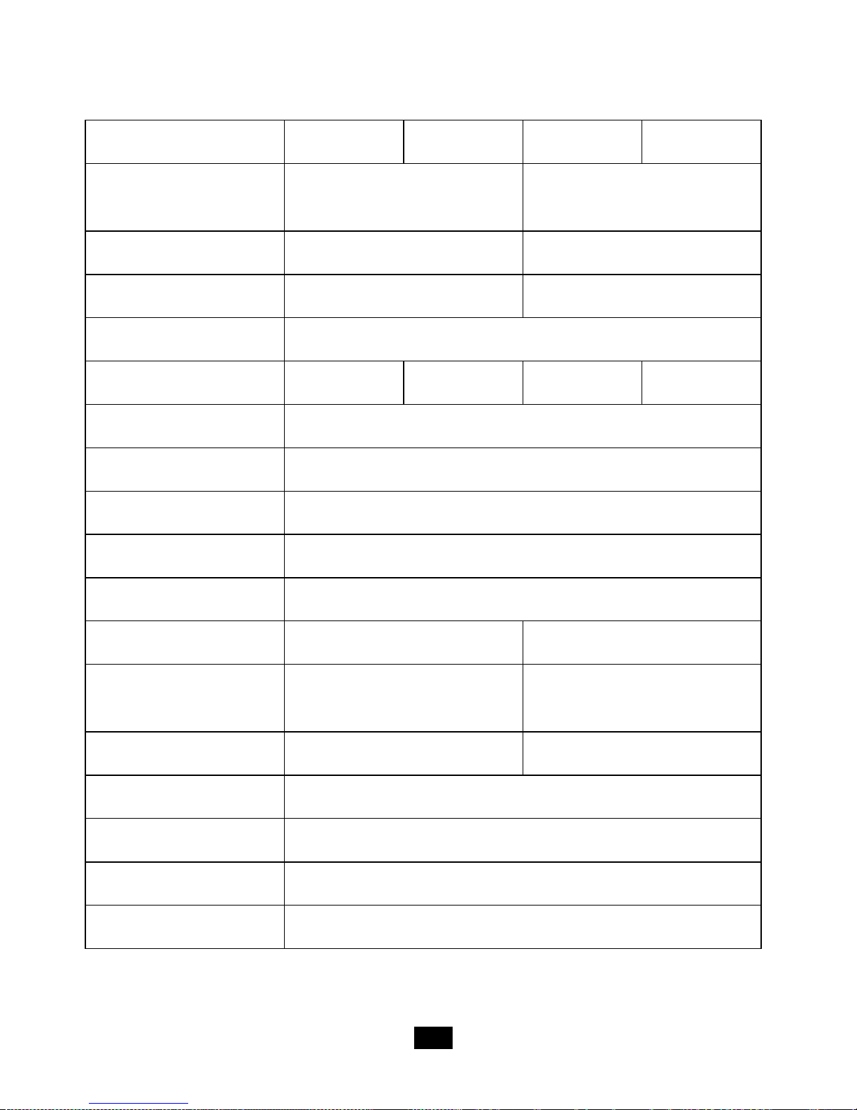
Types
STI300-12-220
STI300-12-230
STI300-24-220
STI300-24-230
Nominal Battery
Voltage
12V
24V
Input Voltage Range
10.5 ~16Vdc
21 ~32Vdc
No Load Consumption
≤5W
≤6W
Output Wave
Pure Sine Wave
Output Voltage
220Vac±3%
230Vac±3%
220Vac±3%
230Vac±3%
Continuous Power
300VA
Power 10 sec
450VA
Power 1.5 sec
600VA
Surge Power
960VA
Frequency
50Hz±0.2%
Distortion THD
≤ 3%( resistive load)
≤ 2%( resistive load)
Efficiency at Rated
Power
≥81%
≥87%
Max. Efficiency
≥90%
≥91%
Dimensions
314.5×166×100.8mm
Installation
200×154mm
Hole Size
Φ8mm
Net Weight
5.3kg
Page 20
16
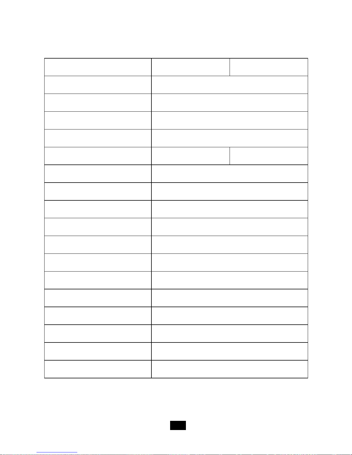
Types
STI500-12-220
STI500-12-230
STI500-24-220
STI500-24-230
Nominal Battery
Voltage
12V
24V
Input Voltage Range
10.5 ~16Vdc
21 ~32Vdc
No Load Consumption
≤5W
≤6W
Output Wave
Pure Sine Wave
Output Voltage
220Vac±3%
230Vac±3%
220Vac±3%
230Vac±3%
Continuous Power
500VA
Power 10 sec
750VA
Power 1.5 sec
1000VA
Surge Power
1600VA
Frequency
50Hz±0.2%
Distortion THD
≤ 5%( resistive load)
≤ 2%( resistive load)
Efficiency at Rated
Power
≥81%
≥87%
Max. Efficiency
≥91%
≥93%
Dimensions
324.5×186.6×111.8mm
Installation
200×174.6mm
Hole Size
Φ8mm
Net Weight
7.3kg
Page 21
17
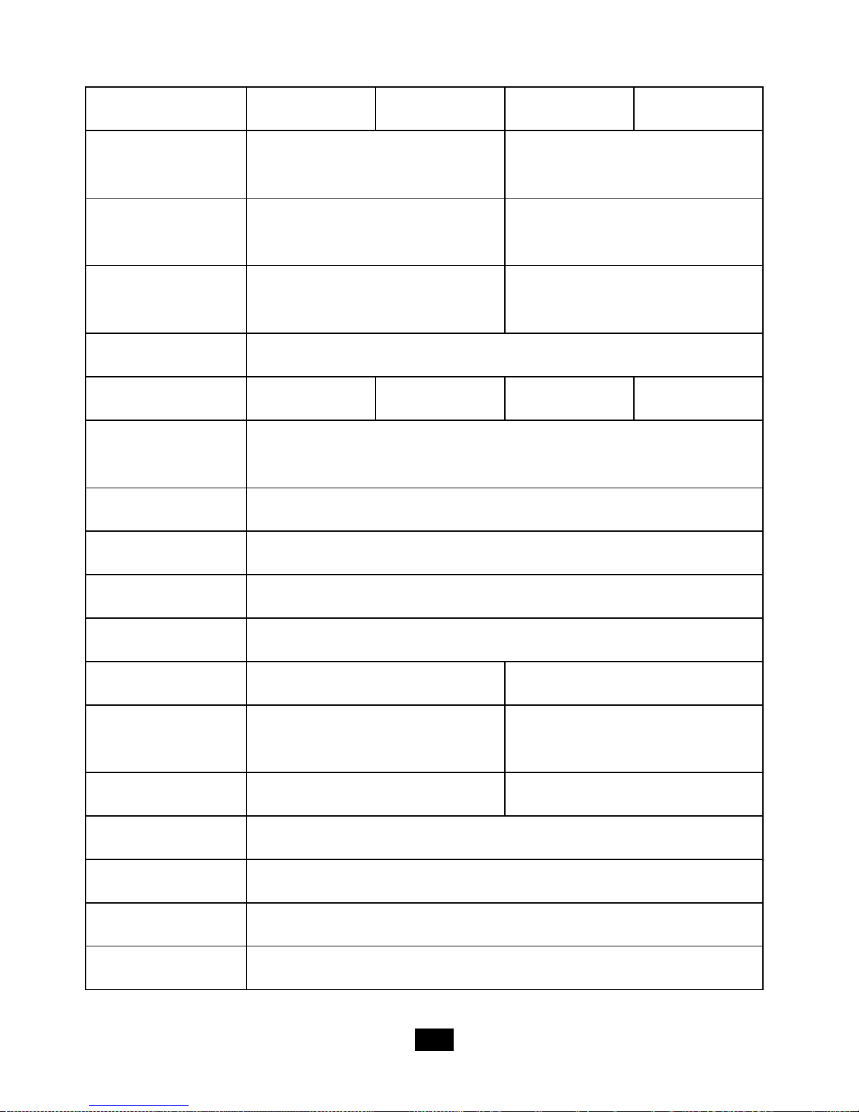
Types
STI700-24-220
STI700-24-230
Nominal Battery voltage
24V
Input Voltage Range
21 ~32Vdc
No Load Consumption
≤8.5W
Output Wave
Pure Sine Wave
Output Voltage
220Vac±3%
230Vac±3%
Continuous Power
700VA
Power 10 sec
1050VA
Power 1.5 sec
1400VA
Surge Power
2240VA
Frequency
50Hz±0.2%
Distortion THD
≤ 3%( resistive load)
Efficiency at Rated Power
≥87%
Max. Efficiency
≥93%
Dimensions
335×232×123.3mm
Installation
230×216mm
Hole Size
Φ8mm
Net Weight
9.4kg
Page 22
18
Types
STI1000-24-220
STI1000-24-230
STI1000-24-220
STI1000-48-230
Nominal Battery
Voltage
24V
48V
Input Voltage
Range
21 ~32Vdc
42 ~64Vdc
No Load
Consumption
≤10W
≤12W
Output Wave
Pure Sine Wave
Output Voltage
220Vac±3%
230Vac±3%
220Vac±3%
230Vac±3%
Continuous
Power
1000VA
Power 10 sec
1500VA
Power 1.5 sec
2000VA
Surge Power
3200VA
Frequency
50Hz±0.2%
Distortion THD
≤ 3%( resistive load)
≤ 2%( resistive load)
Efficiency at
Rated Power
≥87%
≥89%
Max. Efficiency
≥93%
≥94%
Dimensions
373×232×123.3mm
Installation
260×216mm
Hole Size
Φ8mm
Net Weight
11.8kg
Page 23
19
Environmental Parameters
Working Temperature
-20℃~+50℃
Storage Temperature
-35℃~ +70℃
Humidity
< 95%(N.C.)
Altitude
< 5000 m (Derating to operate according to IEC62040 at
a height exceeding 1000 m)
Others
Insulation Resistance
Between DC input terminals and metal case: ≥550MΩ;
Between AC output terminals and metal case: ≥550MΩ.
Dielectric Strength
Between DC input terminals and metal case:
Test voltage AC1500V, 1 minute
Between AC output terminals and metal case:
Test voltage AC1500V, 1 minute
Version No. : V1.2
Page 24

Page 25

BEIJING EPSOLAR TECHNOLOGY CO., LTD.
Tel: +86-10-82894112 / 82894962
Fax: +86-10-82894882
E-mail: [email protected]
Website: http://www.epsolarpv.com/
 Loading...