

Page 1
BEIJING EPSOLAR TECHNOLOGY CO., LTD. Tel:+86-10-82894112 / 82894962 Website:www.epsolarpv.com/www.epever.com
1 2
LandStar B series
——Solar Charge Controller
1 Overview
LandStar B series is a PWM common positive solar charge controller that adopts the most
advanced digital technique. The multiple load control modes enable it can be widely used
on solar home system, traffic signal, solar street light, solar garden lamp, etc. The features
are listed below:
Features:
Adopt high quality components of ST,IR and Infineon, make sure product lifespan
Terminals have UL and VDE certification, the product is more safer and more reliable
100% input and output in the environment temperature range
3-Stage intelligent PWM charging:Bulk, Boost/Equalize, Float
Support 3 charging options: Sealed, Gel, Flooded and User
RS485 communication interface and Modbus communication protocol
Battery temperature compensation function
Energy statistics function
Multiple load control modes
Extensive Electronic protection
2 Product Features
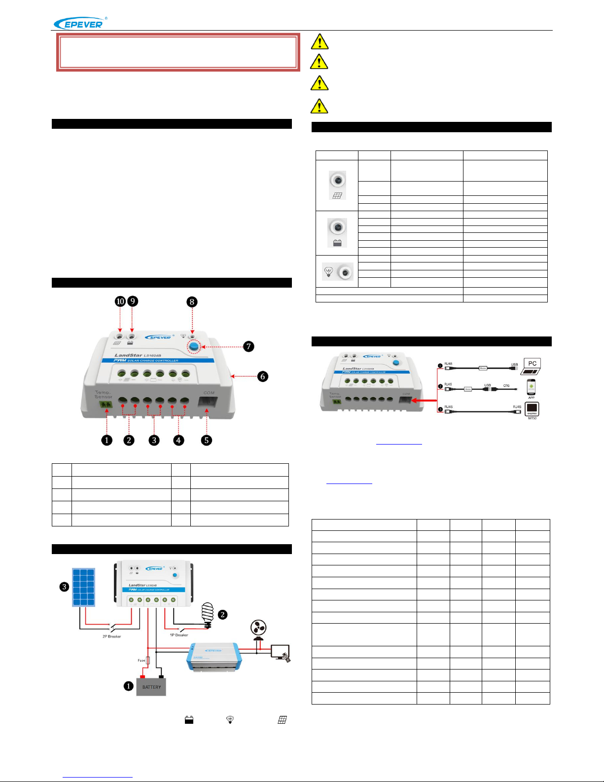
❶
Remote Temperature(RTS)Port★
❻
Mounting Hole
❷
PV Terminals
❼
Button
❸
Battery Terminals
❽
Load status indicator
❹
Load Terminals
❾
Battery status indicator
❺
RS485 communication Port
❿
Charge status indicator
★If the temperature sensor is short-circuited or damaged, the controller will charge
or discharge at the default temperature setting of 25 ºC.
3 Wiring
Installation Procedure:
Connect the system in the order of ❶battery ❷ load ❸PV array in
accordance with Fi gure 2”Connection diagram” and disconnect the system in the reverse
order❸❷❶.
NOTE: The LS-B series is a positive ground controller. Any positive
connection of solar, load or battery can be earth grounded as required.
NOTE:While wiring the controller do not close the circuit breaker or fuse
and make sure that the leads of "+" and "-" poles are connected correctly.
NOTE: A fuse which current is 1.25 to 2 times the rated current of the
controller must be installed on the battery side with a distance from the
battery not greater than 150 mm.
NOTE: If an inverter is to be connected to the system, connect the inverter
directly to the battery, not to the load side of the controller.
4 Indicator and button
(1)Indicator
Indicator
Color
Status
Information
Green
On Solid
PV connection normal ,but
low voltage(low irradiance)
from PV, no charging
Green
OFF
No PV voltage(night time)
or PV connection problem
Green
Slowly Flashing(1Hz)
In charging
Green
Fast Flashing(4Hz)
PV Over voltage
Green
On Solid
Normal
Green
Slowly Flashing(1Hz)
Full
Green
Fast Flashing(4Hz)
Over voltage
Orange
On Solid
Under voltage
Red
On Solid
Over discharged
Red
Slowly Flashing(1Hz)
Battery Overheating
Red
On Solid
Load ON
Red
OFF
Load OFF
Red
Slowly Flashing(1Hz)
Load overload
Red
Fast Flashing(4Hz)
Load short circuit
Charge, Load and Battery(orange)indicator flashing
Controller Overheating
Charge, Load and Battery(red)indicator flashing
System voltage error
(2)Button
①The load is turned ON/OFF via the button when the working mode is Manual Control.
②Clear the faults for the load overload and short circuit .
5 Setting
❶ USB to RS485 converter cable: CC- RS485-RS485-150U
PC software website: www.epever.com(PC Software for the Solar Charge Controller)
❷ USB to RS485 converter cable: CC- RS485-RS485-150U
OTG cable: OTG-12CM
Phone APP software website (support Andriod system only)
www.epever.com(Andriod APP for the Solar Charge Controller)
❸ USB to RS485 converter cable:CC-RS485-RS485-200U-MT)
(1)Battery types
Battery Voltage Control Parameters
Below parameters are in 12V system at 25 ºC, please double the values in 24V system
Battery type
Sealed
Gel
Flooded
User
Over Voltage Disconnect Voltage
16.0V
16.0V
16.0V
9~17V
Charging Limit Voltage
15.0V
15.0V
15.0V
9~17V
Over Voltage Reconnect Voltage
15.0V
15.0V
15.0V
9~17V
Equalize Charging Voltage
14.6V
——
14.8V
9~17V
Boost Charging Voltage
14.4V
14.2V
14.6V
9~17V
Float Charging Voltage
13.8V
13.8V
13.8V
9~17V
Boost Reconnect Charging Voltage
13.2V
13.2V
13.2V
9~17V
Low Voltage Reconnect Voltage
12.6V
12.6V
12.6V
9~17V
Under Voltage Warning Reconnect
Voltage
12.2V
12.2V
12.2V
9~17V
Under Voltage Warning Voltage
12.0V
12.0V
12.0V
9~17V
Low Voltage Disconnect Voltage
11.1V
11.1V
11.1V
9~17V
Discharging Limit Voltage
10.6V
10.6V
10.6V
9~17V
Equalize Duration
120 min
——
120 min
0~180 min
Boost Duration
120 min
120 min
120 min
10~180 min
NOTE:
1) When the battery type is sealed, gel, flooded, the adjusting range of equalize duration is
0 to180min and boost duration is 10 to180min.
2) The following rules must be observed when modifying the parameters value in user
Figure 1 Characteristic
Figure 2 Connection diagram
※Thank you for selecting the LandStar B series solar charge controller.
Please read this manual carefully before using the product and pay attention
to the safety information.
Page 2
BEIJING EPSOLAR TECHNOLOGY CO., LTD. Tel:+86-10-82894112 / 82894962 Website:www.epsolarpv.com/www.epever.com
3 4
battery type (factory default value is the same as sealed type):
A. Over Voltage Disconnect Voltage > Charging Limi t Voltage ≥ Equalize Charging
Voltage ≥ Boost Charging Voltage ≥ Float Charging Voltage > Boost Reconnect Charging
Voltage.
B. Over Voltage Disconnect Voltage > Over Voltage Reconnect Voltage.
C. Low Voltage Reconnect Voltage > Low Voltage Disconnect Voltage ≥ Discharging Limit
Voltage.
D. Under Voltage Warning Reconnect Voltage > Under Voltage Warning Voltage ≥
Discharging Limit Voltage.
E. Boost Reconnect Charging voltage > Low Voltage Disconnect Voltage.
CAUTION: Please refer to user guide or contact with the sales for the
detail of setting operation.
(2)Load Set Mode
1)Manual Control(default ON)
The load is turned ON/OFF via the button.
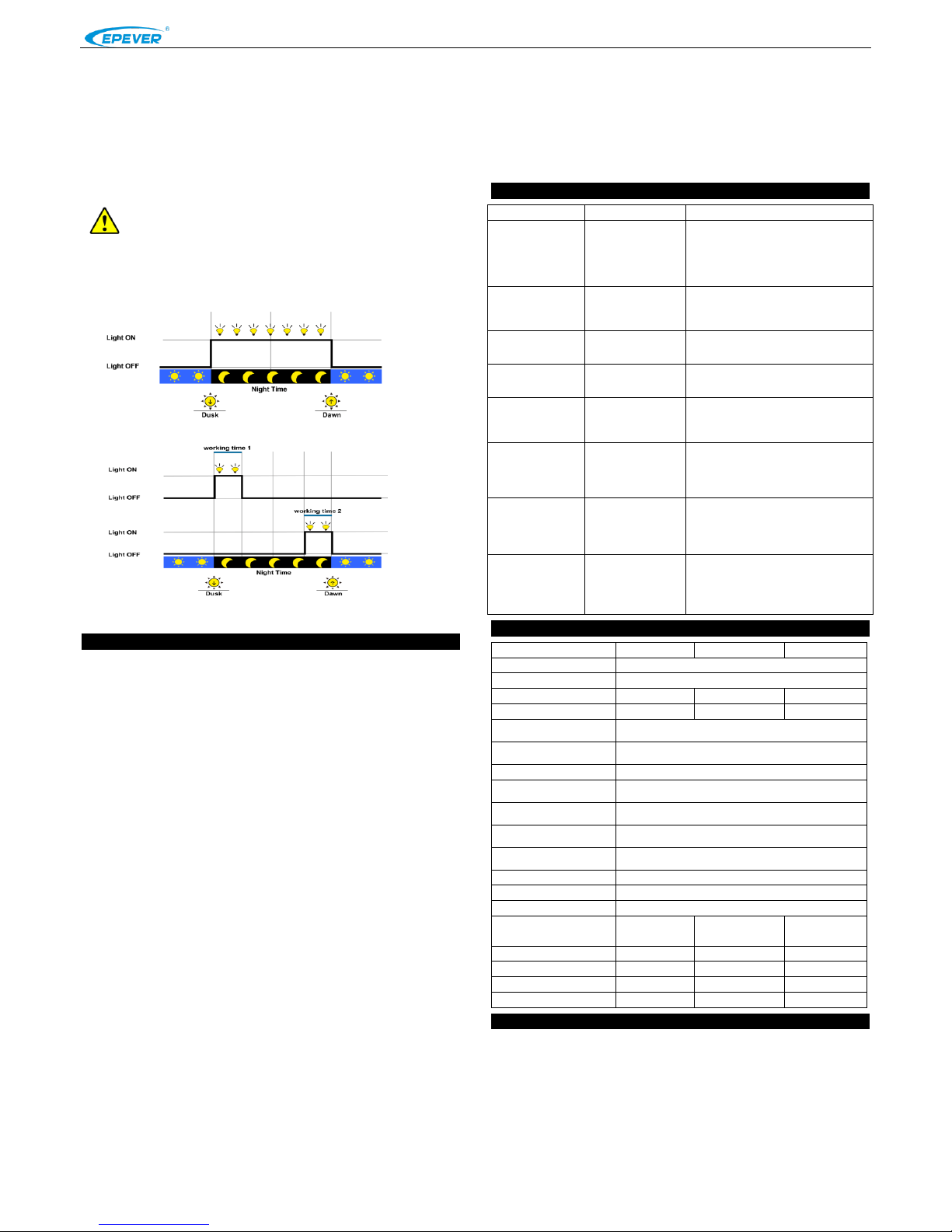
2)Light ON/OFF
3) Light ON/OFF + Timer
4)Time Control
Control the load on/off time through setting real-time clock.
6 Protections
PV Over Current
When the charging power of the PV array exceeds its rated power, it will be charged at
the rated power.
PV Short Circuit
When not in PV charging state, the controller will not be damaged in case of a
short-circuiting in the PV array.
PV Reverse Polarity
When the polarity of the PV array is reversed, the controller may not be damaged and
can continue to operate normally after the polarity is corrected.
Battery Reverse Polarity
Fully protected against battery reverse polarity; no damage to the controller will result.
Correct the miswire to resume normal operation.
Battery Over Voltage
When the battery voltage reaches the over voltage disconnect voltage, it will
automatically stop battery charging to prevent battery damage caused by over-charging.
Battery Over Discharge
When the battery voltage reaches the low voltage disconnect voltage, it will
automatically stop battery discharging to prevent battery damage caused by
over-discharging. (Any controller connected loads will be disconnected. Loads directly
connected to the battery will not be affected and may continue to discharge the battery.)
Battery Overheating
The controller can detect the battery temperature through an external temperature
sensor. The controller stops working when its temperature exceeds 65 °C and begins
working when its temperature is below 55 °C.
Load Overload
When the load is overloading (The overload current is ≥ 1.05 times the rated load
current), the controller will automatically cut off the output. If the load reconnects
automatically five times (delay of 5s, 10s, 15s, 20s, 25s), it needs to be cleared by
pressing the Load button restarting the controller, switching from Night to Day
(nighttime > 3 hours).
Load Short Circuit
When the load is short circuited (The short circuit current is ≥ 2 times the rated controller
load current), the controller will automatically cut off the output. If the load reconnects
the output automatically five times (delay of 5s, 10s, 15s, 20s, 25s), it needs to be
cleared by pressing the Load button, restarting the controller or switching from Night to
the Day (nighttime > 3 hours).
Controller Overheating
The controller is able to detect the temperature inside the battery through an optional
remote sensor. The controller stops working when its temperature exceeds 85 °C and
begins to working when its temperature is below 75 °C.
TVS High Voltage Transients
The internal circuitry of the controller is designed with Transient Voltage Suppressors
(TVS) which can only protect against high-voltage surge pulses with less energy. If the
controller is to be used in an area with frequent lightning strikes, it is recommended to
install an external surge arrester.
7 Troubleshooting
Faults
Possible reasons
Troubleshooting
Charging LED
indicator off during
daytime when
sunshine falls on
PV modules
properly
PV array
disconnection
Confirm that PV and battery wire
connections are correct and tight
Wire connection is
correct, the
controller is not
working.
Battery voltage is
lower than 8V
Please check the voltage of battery. At
least 8V voltage to activate the
controller.
Battery indicator
green slowly
flashing
Battery over
voltage
Check if battery voltage is higher than
OVD(over voltage disconnect voltage),
and disconnect the PV.
Battery indicator
red on solid
Battery over
discharged
When the battery voltage is restored to
or above LVR(low voltage reconnect
voltage), the load will recover
Battery indicator
red slowly flashing
Battery
Overheating
The controller will automatically turn the
system off. But while the temperature
decline to be below 55 ºC, the controller
will resume.
Charge, Load and
Battery(orange)indi
cator flashing
Controller
Overheating
When heat sink of controller exceeds
85℃, the controller will automatically cut
input and output circuit. When the
temperature below 75℃,the controller
will resume to work.
Load indicator red
slowly flashing
Load Overload
①Please reduce the number of electric
equipments.
②Restart the controller.
③wait for one night-day cycle (night
time>3 hours).
Load indicator red
fast flashing
Load Short Circuit
①Check carefully loads connection, clear
the fault.
②Restart the controller.
③wait for one night-day cycle (night
time>3 hours).
8.Technical Specifications
Item
LS1024B
LS2024B
LS3024B
System nominal voltage
12/24VDC Auto
Battery Types
Sealed/Gel/Flooded/User
Rated charge current
10A
20A
30A
Rated discharge current
10A
20A
30A
Working Voltage range of
controller
8~32V
Max. PV open circuit
voltage
50V
Self-consumption
≤8.4mA/12V;≤7.8mA/24V
Charge circuit voltage
drop
≤0.28V
Discharge circuit voltage
drop
≤0.20V
Temperature compensate
coefficient
-3mV/℃/2V (default)
Working environment
temperature
-35℃~+50℃
Relative humidity
≤95% (N.C.)
Enclosure
IP30
Grounding
Common Positive
Dimension
138.6x69.3
x37mm
159.6x81.4
x47.8mm
200.6x101.3
x57mm
Mounting dimension
126mm
147x50mm
190x70mm
Mounting hole size
Φ4.3
Φ4.3
Φ4.5
Terminal
4mm2
10mm2
10mm2
Weight
0.13kg
0.3kg
0.5kg
9.Disclaimer
This warranty does not apply under the following conditions:
Damage from improper use or use in an unsuitable environment.
PV or load current, voltage or power exceeding the rated value of controller.
The controller is working temperature exceed the limit working environment
temperature.
User disassembly or attempted repair the controller without permission.
The controller is damaged due to natural elements such as lighting.
The controller is damaged during transportation and shipment.
Any changes without prior notice! Version number:V2.5
 Loading...