

Page 1
BEIJING EPSOLAR TECHNOLOGY CO., LTD. Tel:+86-10-82894112 / 82894962 Website:www.epsolarpv.com/www.epever.com
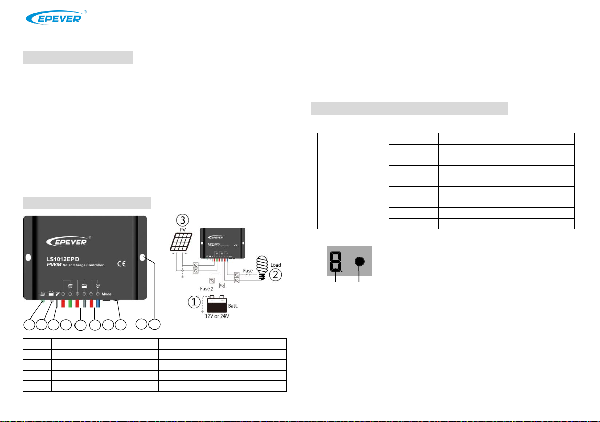
①
Charging Status LED indicator
⑥
Load Terminals
②
Battery Status LED indicator
⑦
Digital tube
③
Temperature Sensor
⑧
Key
④
Solar Module Terminals
⑨
Aluminum housing
⑤
Battery Terminals
⑩
Mounting hole Φ5
Charging Status
LED indicator
Green
On Solid
Normal
Green
Fast Flashing
Over voltage
Battery Status LED
indicator
Green
On Solid
Normal
Green
Slowly Flashing
Full
Orange
On Solid
Under voltage
Red
On Solid
Over discharged
Radix Point of Digital
tube
(Load indicator)
Red
On Solid
Load ON
Red
Slowly Flashing
Over Load
Red
Fast Flashing
Short Circuit
Figure1 Mounting
Digital tube
Key
3 5 1 2 4 6 7 8 9
10
LS-EPD Series Solar Charge Controller
1. General Information
LS-EPD series solar charge controller adopts the most advanced digital technique and
operates fully automatically. It is ideal for extreme environments with corrosion, dust, water
etc and has various unique functions:
Electronic protection: Over charging, over discharging, overload, short circuit and reverse
protection of solar module
High efficient Series PWM charging, increase the battery lifetime and improve the solar
system performance
Widely used, automatically recognize day/night
Battery LED indicate battery status
Industrial design, wide application range
Digital tube menu, only one key solve all setting simply
Intelligent timer function with 1~13 hours option
IP67 protection
Mounting
1) Connect components to the charge controller in the sequence as shown above picture
and pay much attention to the “+” and “-”. Always power the battery firstly.
2) After power the battery, check the battery indicator on the controller, it will be green. If it’s
not green, please refer to chapter 4.
3) The battery fuse should be installed as close to battery as possible. The suggested
distance is within 150mm.
3. Indicators Description and Operation
1) Indicator Status Description
2. Features and Mounting
1 2
2) Operation
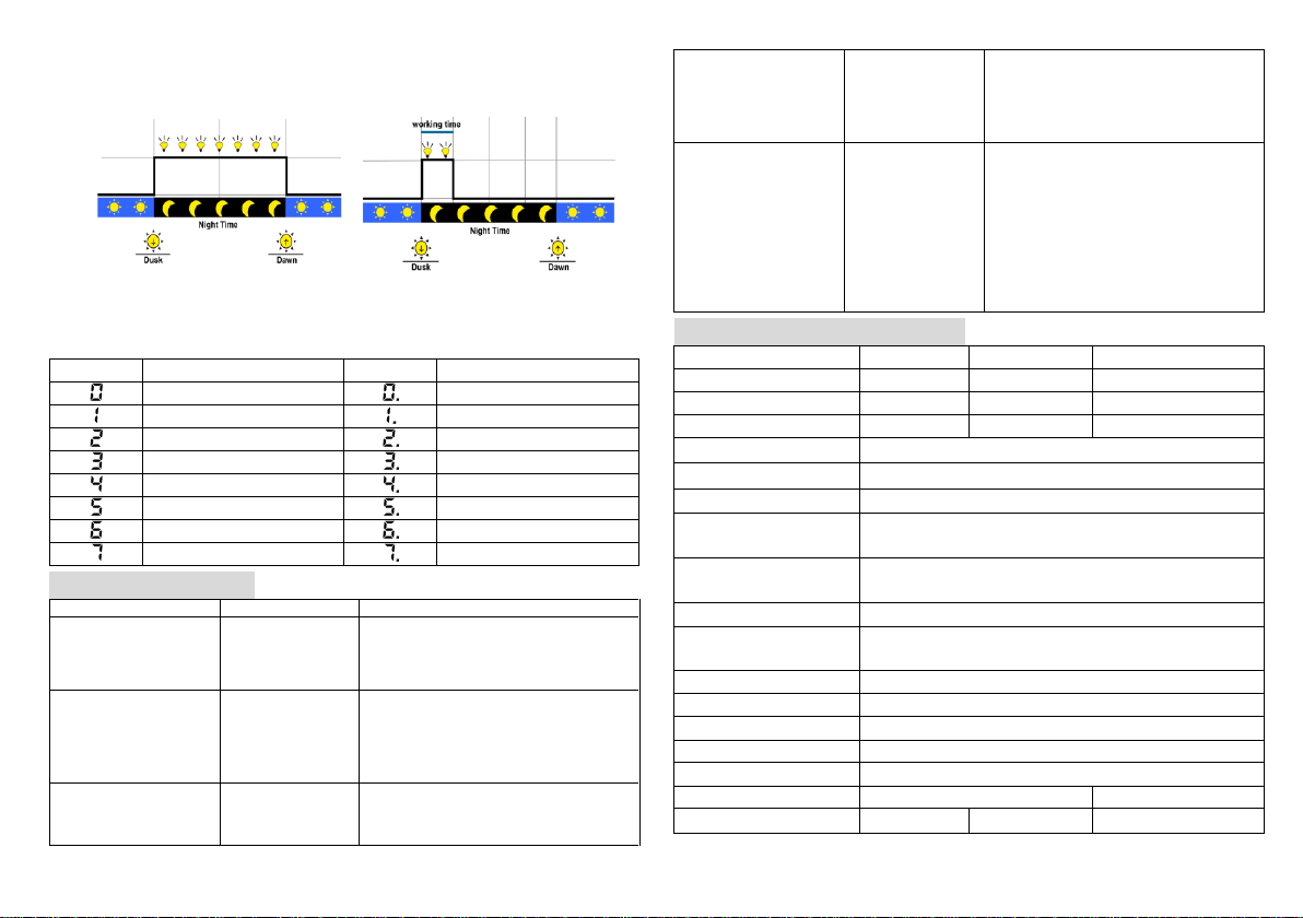
The digital tube display the load work mode, please refer to the
correspondence table of Load Work Mode & LED digital tube value.
Pressing the key to configure the parameter, please refer to the
below configuration method:
1) After Powering on, disconnect the PV or connect the PV(Voltage<5V) , the light of the
digital tube point go on; Connect the PV(Voltage>6V) ,the light of the digital tube point
go off.
2)The key can be used to operate switching on/off the load (Manual control) or clearing
the faults
3) Keeping pressing the button over 5S, It will go to the parameter in browsing mode
which can cycle through the parameter item by clicking the button ,after the light of the
digital tube point going on.
4) After the digital tube displaying the value what you want to configure, releasing the key
and waiting 15S, Digital Tube stop flashing, then the configuration is successful.
Page 2
Load mode
Value
Working mode
Value
Working mode
Light ON/OFF
Light ON + 8 hours
Light ON + 1 hours
Light ON + 9 hours
Light ON + 2hours
Light ON + 10 hours
Light ON + 3hours
Light ON + 11 hours
Light ON + 4 hours
Light ON + 12 hours
Light ON + 5 hours
Light ON + 13 hours
Light ON + 6 hours
Manual Control
Light ON + 7 hours
Test Mode
Faults
Possible reasons
Troubleshooting
Charging LED indicator
off during daytime
when sunshine falls on
PV modules properly
PV array
disconnection
Check that PV and battery wire
connections are correct and tight
Charging Status LED
indicator fast flashing
Battery voltage
higher than over
voltage
disconnect
voltage
1. Disconnect the solar array and
measure the battery voltage whether is
too high; 2. Change the controller; 3.
Change the battery
Battery LED indicators
red color and loads not
working
Battery over
discharged
The controller cut off the output
automatically. LED indicator will return to
green automatically when fully
The radix point of
digital tube fast
flashing and load not
working
Short circuit
Clear short circuit. It is reactivated after
delayed 10 seconds for the first time, If
over 1 time,press the key to clear error
and the controller will resume to work
after 3s or restart the controller
The radix point of
digital tube slowly
flashing and load not
working
Over load
Please reduce the number of electric
equipments.
When load power reaches 1.25-1.5
times, 1.5-2 times and 2 times more than
nominal value, controller will
automatically close loads in 60 seconds,
5 seconds and 1 second, respectively.
Please press the key to clear error and
the controller will resume to work after 3s
or restart the controller
Item
LS1012EPD
LS1024EPD
LS2024EPD
Nominal system voltage
12VDC
12/24VDC Auto
12/24VDC Auto
Max. PV input voltage
30V
50V
50V
Rated current
10A
10A
20A
Equalize Voltage
14.8V(12V);29.6V(24V)
Boost Voltage
14.4V(12V);28.8V(24V)
Float Voltage
13.7V(12V);27.4V(24V)
Low Voltage Reconnect
Voltage
12.6V(12V);25.2V(24V)
Low Voltage Disconnect
Voltage
11.2V(12V);22.4V(24V)
Self-consumption
12V:≤4.58mA;24V:≤6.01mA
Temperature
compensation coefficient
-5mV/℃/2V(25℃)
Working temperature
-35℃~+55℃
Enclosure
IP67
Overall dimension
108.5mm×75mm×25.6mm
Mounting dimension
100.5mm
Mounting hole size
Φ5
Power cable
PV/BAT/LOAD:4.0mm
2
PV/BAT/LOAD:6.0mm2
Net weight
408g
410g
435g
● Manual Control:Control the load via the button.
●Light ON/OFF ●Light ON + Timer
Note: In the mode of Light ON/OFF and Light ON/Timer, the Load is turned on after
10Min. delay.
● Test Mode (Default):Test Mode is as same as Light Control Mode but no delay.
The correspondence table of Load Work Mode & LED digital tube value
4. Troubleshooting
6. Technical Specifications
3 4
Any changes without prior notice! Version number:V1.1
 Loading...