

Page 1

LS-E Series
—— Solar Charge Controller
EPEVER
USER
MANUAL
Page 2

Page 3
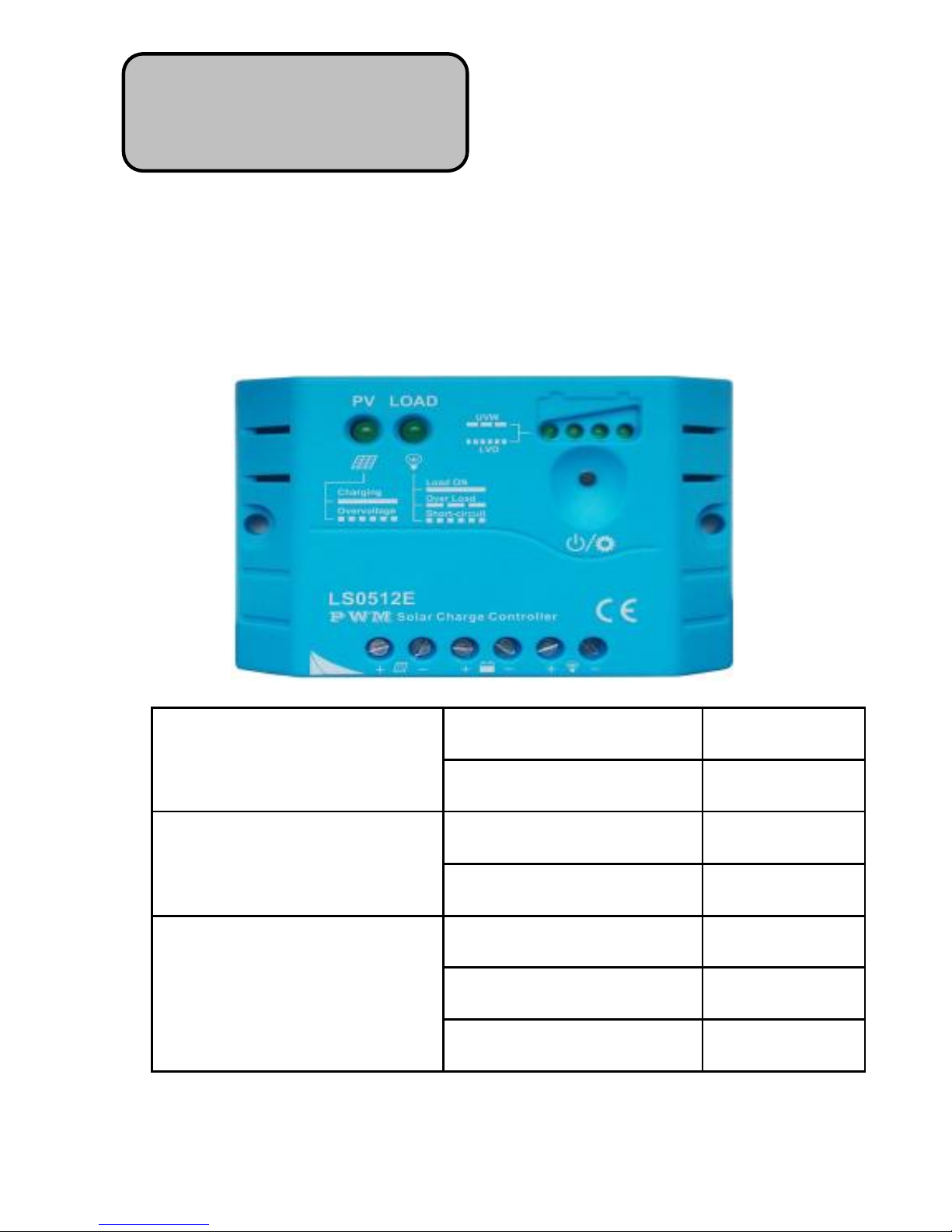
LS-E Series
—— Solar Charge Controller
Nominal System Voltage
LS0512E/LS1012E
12VDC
LS1024E/LS2024E
12/24VDC
Maximum PV Input
Voltage
LS0512E/LS1012E
30V
LS1024E/LS2024E
50V
Nominal
Charge/Discharge Current
LS0512E
5A
LS1012E/LS1024E
10A
LS2024E
20A
LandStar
Page 4

Contents
1 Important Safety Information ..........................................1
2 General Information........................................................ 2
3 Installation Instructions...................................................3
3.1 Mounting ...............................................................3
3.2 Wiring ...................................................................4
4 Operation ................................ ........................................5
4.1 LED Indicators ......................................................5
4.2 Setting Operation ...................................................7
5 Protection and Troubleshooting ......................................8
5.1 Protection ..............................................................8
5.2 Troubleshooting .....................................................9
6 Technical specifications ................................................ 11
Page 5

1
1 Important Safety Information
Read all of the instructions and cautions in the manual before
beginning installation.
There are no user serviceable parts inside the controller. Do not
disassemble or attempt to repair it.
Install external fuses/breakers as required.
Disconnect the solar module and fuse/breakers near to battery before
installing or adjusting the controller.
Do not allow water to enter the controller.
Confirm that power connections are tightened to avoid excessive
heating from loose connection.
Page 6

2
2 General Information
LS-E series solar charge controller, with beautiful, economic, practical,
simple and easy to use, etc. It has various unique functions:
High efficient Series PWM charging, increase the battery lifetime
and improve the solar system performance.
Battery LED indicator can indicates battery situation.
Support 3 charging options: Sealed, Gel and Flooded.
Adopt temperature compensation, correct the charging and
discharging parameters automatically and improve the battery
lifetime.
Electronic protection: load overload and short circuit, battery over
discharging, over voltage, low voltage and reverse protection.
With humanized Settings, operation will be more comfortable and co
nvenient.
Industrial design, wide application range.
Page 7

3
3 Installation Instructions
3.1 Mounting
Read through the entire installation section first before beginning
installation.
Be very careful when working with batteries. Wear eye protection.
Have fresh water available to wash and clean any contact with
battery acid.
Uses insulated tools and avoid placing metal objects near the
batteries.
Explosive battery gasses may be present during charging. Be certain
there is sufficient ventilation to release the gasses.
Avoid direct sunlight and do not install in locations where water can
enter the controller.
Loose power connections and/or corroded wires may result in
resistive connections that melt wire insulation, burn surrounding
materials, or even cause fire. Ensure tight connections and use cable
clamps to secure cables and prevent them from swaying in mobile
applications.
Use with Gel, Sealed or Flooded batteries only.
Battery connection may be wired to one battery or a bank of batteries.
The following instructions refer to a singular battery, but it is
implied that the battery connection can be made to either one
battery or a group of batteries in a battery bank.
Select the system cables according to 3.5A/mm2 current density.
Page 8
4
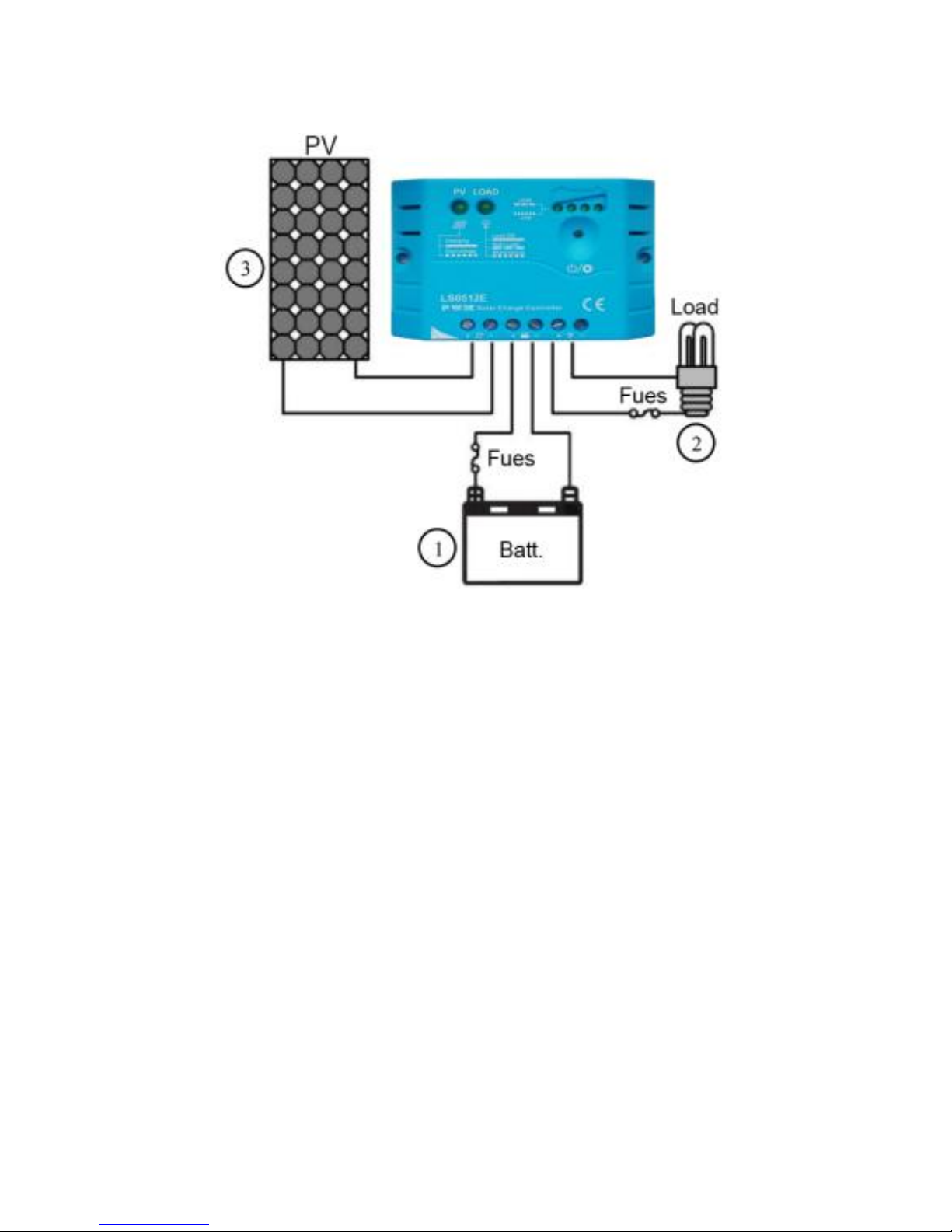
3.2Wiring
1. Connect components to the charge controller in the sequence as
shown in above picture and pay much attention to the “+” and
“-”.Always power the battery First.
2. After power the battery, check the battery indicator on the
controller, it will be green. If it’s not green, please refer to chapter
5.
3. The load should be DC applicant with the same rated voltage as
battery’s. Controller offers power to loads through the battery
voltage.
Page 9
5
4 Operation
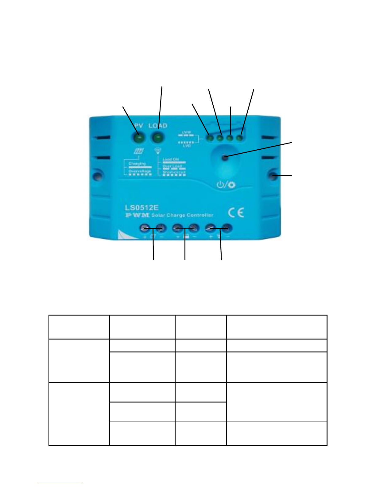
4.1 Features
Charging and load status indicator
Table 4-1
Indicator
Indicator
Status
System
Status
Note
Charging
status
indicator
On
Charging
Normal
Fast
Flashing
Over
voltage
Refer to section 5
Load status
indicator
On
Load ON
Normal
OFF
Load OFF
Slowly
Flashing
Overload
When the load amp is
1.25times of rated
Charging status indicator
Load status indicator
LED1
Setting
button
Solar Module
Terminals
Battery
Terminals
Load
Terminals
Mounting
Holes
LED2
LED3
LED4
Page 10

6
current for 60 seconds,
or the load amp is 1.5
times of rated current for
5 seconds
Fast
Flashing
Refer to section 5
Battery status indicator(LED1、LED2、LED3、LED4)
Battery LED indicator(The parameters in the table below is for 12VDC
system at 25℃, for 24VDC system ,the parameters is doubled)
Table 4-2
LED1
LED2
LED3
LED4
Battery Status
Slowly
Flashing
× × ×
Under voltage
Fast
Flashing
× × ×
Over discharged
Battery LED indicator status during voltage is up
○
○ × ×
12.8V< U
bat
<13.4V
○
○
○
×
13.4V< U
bat
<14.1V
○
○
○
○
14.1V < U
bat
Battery LED indicator status during voltage is down
○
○
○
×
12.8V<U
bat
<13.4V
○
○
×
×
12.4V<U
bat
<12.8V
○
×
×
×
U
bat
<12.4V
“○”LED indicates on “×”LED indicates off “U
bat
”battery voltage
Page 11
7
4.2 Setting Operation
Load Work Mode Setting
When the controller is powered on, press the setting button to control
the load output. Press the button once, the ON/OFF status will be
changed corresponding.
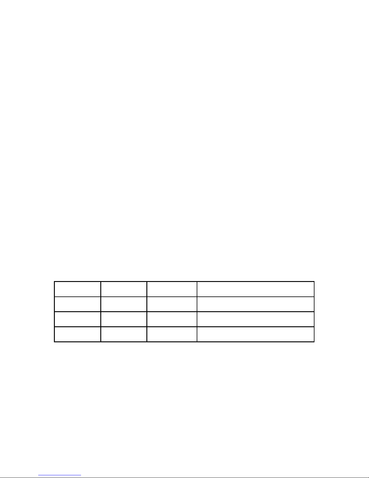
Battery Type Setting
Press the setting button for more than 5 seconds, battery indicator
LED1, LED2, LED3 will be flashing correspondingly. Then press the
setting button to choose Sealed, Gel, and Flooded battery type, when
you finish choosing, stop pressing the button, the setting is finished till
the digital tube stop flashing. The parameters indicated are shown
below:
Battery type selection Table4-4
LED1
LED2
LED3
Battery type
○ × ×
Sealed lead acid battery
○ ○ ×
Gel battery
○ ○ ○
Flooded battery
“○”LED indicator on “×”LED indicator off
Page 12

8
5 Protection and Troubleshooting
5.1 Protection
·Load Overload
If the load current exceeds 1.25 times of rated current for 60 seconds,
or the load amp is 1.5 times of rated current for 5 seconds, the
controller will disconnect the load. Overload must be cleared up
through powering on again or pressing the setting button.
·Load Short Circuit
Fully protected from load wiring short circuit (exceeds 2 times of
rated current) automatically. One automatic load reconnect attempt,
the fault must be cleared by reapply power or pressing the setting
button.
·Battery Reverse Polarity
Fully protection form battery reverse polarity, no damage to the
controller will result. Correct the mistake of wiring to resume normal
operation.
·Damaged Local Temperature Sensor
If the temperature sensor short-circuited or damaged, the controller
will be charging or discharging at the default temperature 25℃ to
prevent the battery damaged from overcharging or over discharged.
Page 13

9
·High Voltage Transients
PV is protected from high voltage transients. In lightning prone areas,
additional external suppression is recommended.
5.2 Troubleshooting
Trouble Shooting Table 5-1
Faults
Possible
reasons
Troubleshooting
Charging LED
indicator off
during daytime
when sunshine
falls on PV
modules
properly.
PV
array
disconnection
Check if PV and battery wire
connections are correct and
tight.
Charging LED
indicator fast
flashing
Battery voltage
higher than
over voltage
disconnect
voltage(OVD)
Check if battery voltage is
over high. Disconnect the
solar module.
Battery LED1
indicator
SLOWLY
FLASHING
Battery
under
voltage
When load output is normal,
LED status will return to ON
automatically when fully
charged.
Page 14

10
Battery LED1
indicator
FAST
FLASHING.
Battery
over
discharged
When the controller cut off
the output automatically,
LED status will return to ON
automatically when fully
charged.
Load LED
indicator
SLOWLY
FLASHING
Over load
Please reduce the load and
press the button once, the
controller will resume to
work after 3s.
Load LED
indicator
FAST
FLASHING
Short circuit
When the first short-circuit
occurs, the controller will
automatically resume to work
after 10s; when a second
short-circuit occurs, press the
button, the controller will
resume to work after 3s.
No LED
indicator
battery voltage
lower than 6V
Measure battery voltage with
multi-meter. Min.6V can start
up the controller.
No charging
status LED
indicator with
normal
connection
input voltage of
solar module
lower than
battery voltage
Measure the input voltage of
solar module, the input
voltage must be higher than
battery voltage.
Page 15
11
6 Technical specifications
Electrical Parameters Table 7-1
Description
Type
Parameter
Nominal System Voltage
LS0512E/LS1012E
12VDC
LS1024E/LS2024E
12/24VDC
Max.batt.Volt.to the
controller
LS0512E/LS101E
16V
LS1024E/LS202E
32V
Rated Battery Current
LS0512E
5A
LS1012E/LS102E
10A
LS2024E
20A
Charge Circuit Voltage Drop
ALL
≤0.26V
Discharge Circuit Voltage
Drop
ALL
≤0.15V
Self-consumption
ALL
≤6mA
Temperature Compensation Coefficient Table7-2
Description
Parameter
Temperature Compensation
Coefficient(TEMPCO)*
-5mV/℃/2V (ref)
* Compensation of equalize, boost, float and low voltage disconnect
voltage
Environmental parameters Table 7-3
Environmental parameters
Parameter
Working temperature
-35℃~+55℃
Storage temperature
-35℃~+80℃
Humidity
≤95% N.C.
Enclosure
IP30
Page 16

12
(The parameters in the table below is for 12VDC system at 25℃, for 24VDC
system ,the parameters is doubled)
Battery Voltage Parameters Table 7-4
Charging Parameters
Battery charging setting
Sealed
Gel
Flooded
Over Voltage Disconnect
Voltage
16V
16V
16V
Charging Limit Voltage
15.5V
15.5V
15.5V
Over Voltage Reconnect
Voltage
15V
15V
15V
Equalize Charging Voltage
14.6V
-------
14.8V
Boost Charging Voltage
14.4V
14.2V
14.6V
Float Charging Voltage
13.8V
13.8V
13.8V
Boost Reconnect Charging
Voltage
13.2V
13.2V
13.2V
Low Voltage Reconnect
Voltage
12.6V
12.6V
12.6V
Under Voltage Warning
Reconnect Voltage
12.2V
12.2V
12.2V
Under Voltage Warning
Voltage
12V
12V
12V
Low Voltage Disconnect
Voltage
11.1V
11.1V
11.1V
Discharging Limit Voltage
10.5V
10.5V
10.5V
Equalize Duration
2 hours
-------
2 hours
Boost Duration
2 hours
2 hours
2 hours
Page 17

13
Mechanical Parameters Table 7-5
Type
LS0512E
LS1012E
Overall Dimension
92.8x65x20.2mm
101.2x67x21.8mm
Mounting dimension
84.4mm
92.7mm
Mounting hole size
Φ4.5
Φ4.5
Terminal
2.5mm²
4mm²
Weight
74g
82.5g
Mechanical Parameters Table 7-6
Type
LS1024E
LS2024E
Overall Dimension
101.2x67x21.8mm
128x85.6x34.8mm
Mounting dimension
92.7mm
118mm
Mounting hole size
Φ4.5
Φ4.5
Terminal
4mm²
6mm²
Weight
82g
151.6g
Page 18

Final interpretation right of the manual belongs to our company.
Any changes without prior notice!
Version number: V1.7
Page 19

Page 20

GmbH Faktor
Tel:+49 2080023 8031
E-mail:info@faktor de.
Website: http://www.faktor.de
 Loading...