

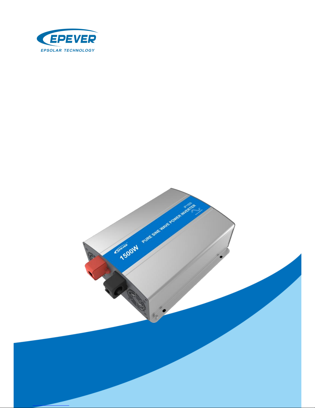
Epever IPower Series, IPower IP1500-12, IPower IP1500-22, IPower IP2000-22, IPower IP2000-42 User Manual
Page 1
1
IPower Series
——Pure Sine Wave Inverter
User’s Manual
Model:
IP1500-12
IP1500-22
IP2000-22
IP2000-42
Page 2

2
Page 3

3
CONTENTS
1. Introduction ........................................................... 1
2. Important Safety Instructions .............................. 2
3. Wiring .................................................................... 4
4. Functions .............................................................. 6
5. Protection ............................................................ 10
6. Troubleshooting .................................................. 12
7. Maintenance and Warranty ............................... 13
8. Technical Specification ...................................... 14
Page 4

1
1. Introduction
Thanks for purchasing IPower series inverters. The product is a
pure sine wave inverter which can convert 12/24/48VDC to
220/230VAC, 50/60Hz based on full digital and intelligent design. It
features high reliability, high efficiency, concise outline, small
volume, full protection functions, easy installation and operation.
The inverter can be applied in many fields, such as household
emergency lighting system, vehicle mounted system and small field
power supply, etc.
Features:
Complete isolation-type inverter technology
Adoption of advanced SPWM technology, pure sine wave output
Dynamic current loop control technology to ensure inverter
reliable operation
Wide DC input voltage range
Low output harmonic distortion (THD≤5%)
Optional output voltage and frequency at 220/230VAC,50/60Hz
High conversion efficiency up to 95%
USB output 5VDC/1A*
RS485 communication port*
Extensive Electronic protection
﹡Only the model of the USB output port or RS485 port.
Page 5

2
2. Important Safety Instructions
As an AC power supply equipment, the inverter’s output voltage is
with the same level as that of household power plug. Mind the AC
output terminals, or you may get an electric shock and result in life
danger!
Attentions:
Connect the DC input according to the requirement strictly. The
power inverter has a relatively wide input range, but too high or
too low input may cause problems even destroy the inverter.
A reverse polarity connection will blow the fuses in the inverter
and may damage the unit.
Do not expose the inverter to humid, flammable, explosive or
dust environment.
Keep the inverter out of children touch.
Inverter input is recommended to connect to battery, the min.
capacity of battery(expressed in AH) should be calculated in the
following way: 5times of the rated power of the inverter/battery
voltage. If for testing purpose, user should select DC power
supply current at least twice greater than that of the inverter
rated input to keep inverter normal operation. Use DC power
supply for testing may cause the damage of the inverter.
When the inverter works continuously, its surface may become
very hot, please make sure the air ventilation clearance around
the inverter is more than 10cm. Keep away from the material or
device which may suffer from high temperature when the
inverter is working. Do not install the inverter in airproof location
and keep enough space around the inverter.
The protective grounding must be connected to the ground. The
cross section of wire should not be less than 4mm2.
Page 6

3
The wire connects between battery and inverter should be
shorter than 3m, the current density should be less than
3.5A/mm2 while the output of inverter is fully loaded. If the wire
longer than 3m, the current density should be reduced.
A fuse or breaker should be used between battery and inverter,
the value of fuse or breaker should be twice of the inverter rated
input current.
Do not connect the battery charger or similar devices to the
input terminal of the inverter.
Do not put the inverter close to the flooded lead-acid battery
because the sparkle in the terminals may ignite the hydrogen
released by the battery.
It’s an off-grid inverter, do not connect the AC output terminals
to the grid or electrical source, otherwise the inverter may be
damaged.
This inverter can only be used singly, parallel connection or in
series will damage the inverters.
Risk of electric shock, don’t touch output port when the inverter
is working. The output is forbidden to connect other power
sources or grid, otherwise the inverter will be damaged. The
inverter must be in off, when connecting load.
Do not attempt to repair the fault inverter by yourself, otherwise it
may lead to a serious accident. Please contact the manufacture’
s engineer.
Page 7
4
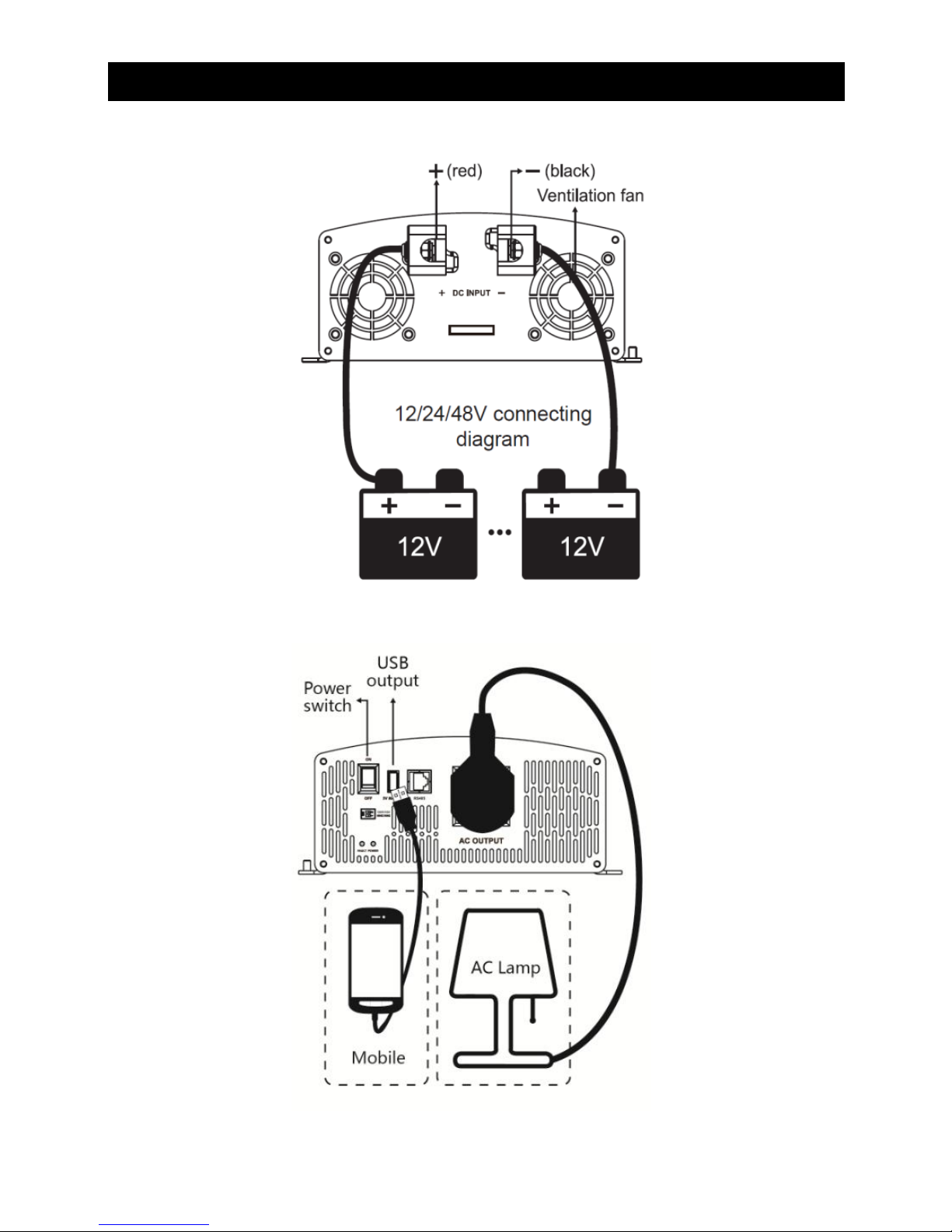
3. Wiring
(1)12/24/48Vsystem DC input
(2) 220/230V AC output
Page 8

5
Operation Steps:
Step 1: Turn off the switch of inverter
Step 2: Connect the battery (‘+’ terminal with red line, ‘-’with black
line). Do not connect them by contraries, or the power inverter will
be damaged.
Step 3: Connect the protective grounding to the ground
Step 4: Connect the AC load to the AC outlet
Step 5: Switch on the fuse or breaker. Switch the inverter to ON
and then turn on the loads one by one. Check the operation state of
both power inverter and loads. ‘Green’ of the Working indicator
means the state is normal.
Step 6: If there are different loads, it is suggested that turn on the
load with large startup current first, such as television, then turn on
the load such as lamp when the inverter works stably.
Step 7: If the Fault indicator is ‘Red’ and the buzzer alarms or no
output when you turn on devices, switch off the loads and
power inverter immediately. Check the system by referring to the
troubleshooting guide. Turn on the devices again according to the
operation methods after the failure is removed.
Page 9
6
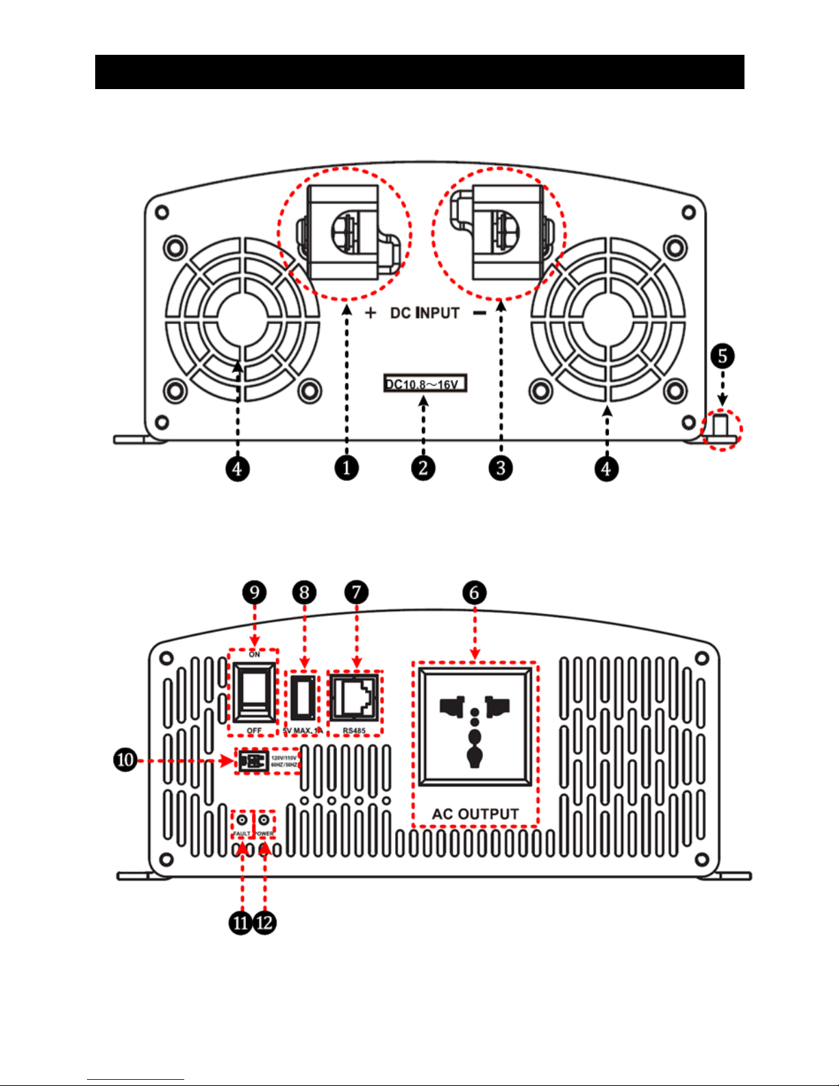
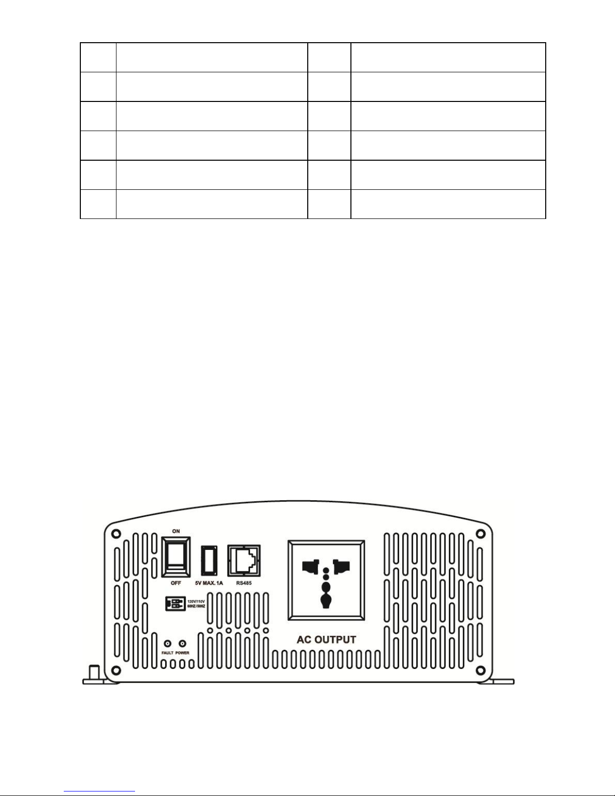
4. Functions
DC Input Panel
AC Output Panel
Page 10
7
❶
DC Input Terminal Positive
❼
RS485 communication port
(4)
❷
DC input voltage range
(1)
❽
USB output port (5VDC/1A)
❸
DC Input Terminal Negative
❾
AC output switch
❹
Ventilation Fan
(2)
❿
Mode switch
(5)
❺
Grounding Terminal
➀
Fault indicator(red)
(6)
❻
AC Outlet
(3)
➁
Working indicator(green)
(6)
(1) Input rated voltage
12V system input voltage range is 10.8~16V;
24V system input voltage range is 21.6~32V;
48V system input voltage range is 43.2~60V。
(2) Fan Ventilation
When the heat sink temperature is higher than 50℃ or internal
temperature is higher than 50℃, the fan will turn on automatically.
When the heat sink temperature is lower than 40℃ and internal
temperature is lower than 40℃, the fan will turn off automatically.
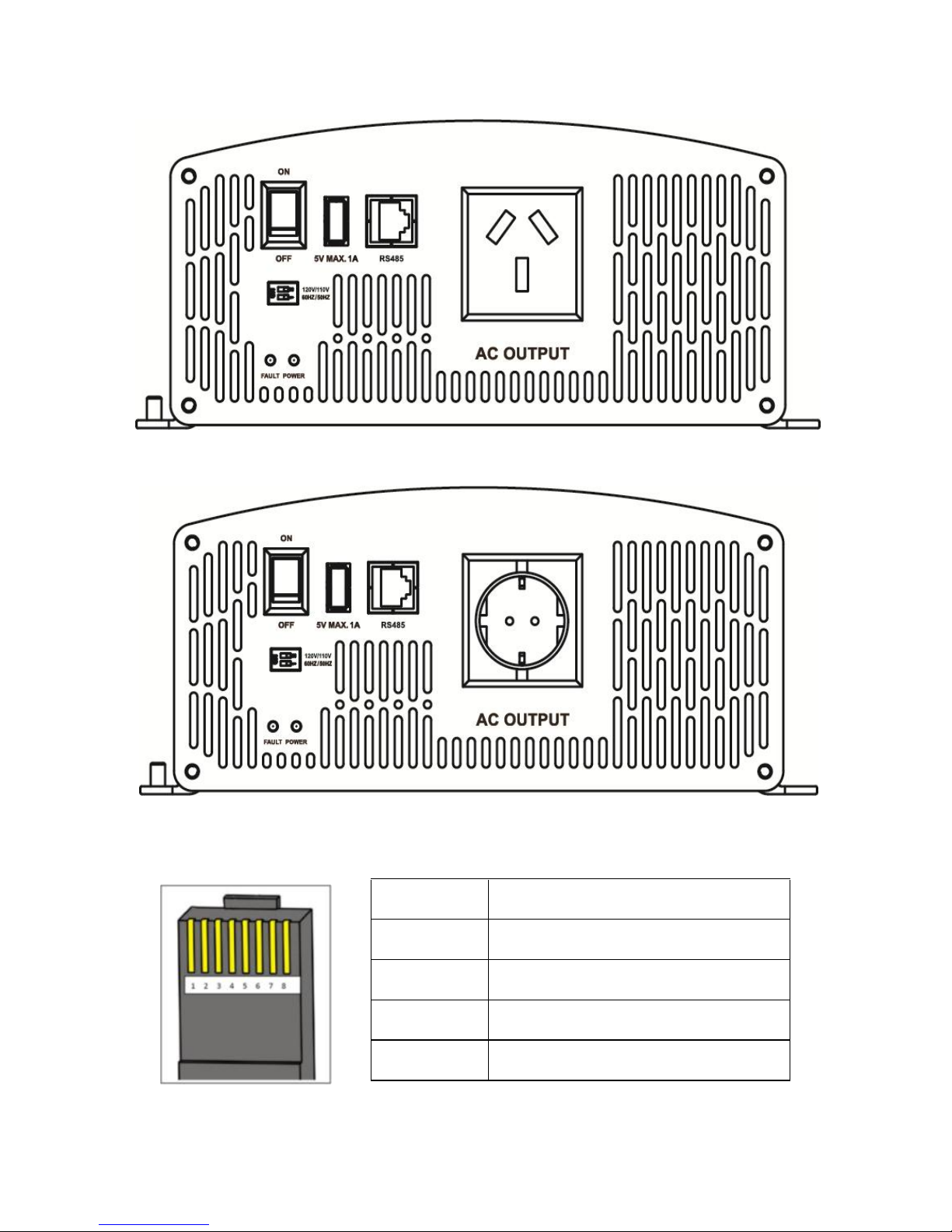
(3) AC Outlet (optional)
Universal
Page 11
8
Australia/New Zealand
European
(4) RS485 communication port
The RJ45 interface pin definition is shown below:
Pins
Define
1/2
—
3/4
RS-485-B
5/6
RS-485-A
7/8
—
Page 12
9
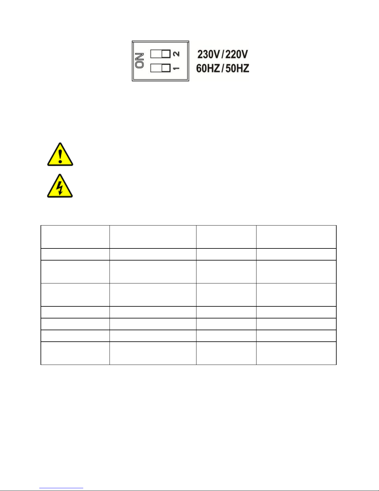
(5) Mode Switch
When the switch No.1 is on the ON side, output frequency is 60Hz, otherwise
is 50Hz.
When the switch No.2 is on the ON side, the output voltage is 230VAC,
otherwise is 220VAC.
NOTE: Both the output frequency and the output voltage
change availability after restart the inverter.
WARNING: DO NOT turn ON/OFF the mode switch when the
inverter is working.
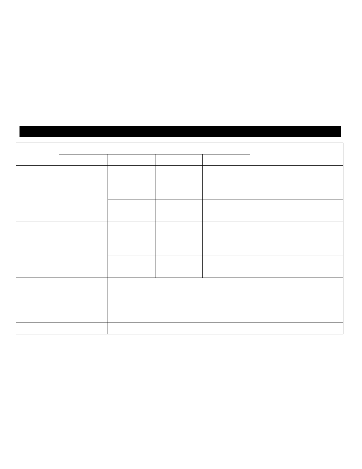
(6) LED indicator and Buzzer
Working
indicator
Fault indicator
Buzzer
Status
Green On Solid
Red OFF
No Sounding
Output is ON
Green Slowly
Flashing
Red OFF
Sounding
Input under
voltage
Green Fast
Flashing
Red OFF
Sounding
Input over voltage
Green On Solid
Red On Solid
Sounding
Over temperature
Green OFF
Red Fast Flashing
Sounding
Load short circuit
Green On Solid
Red Slowly Flashing
Sounding
Overload
Green OFF
Red OFF
Sounding
Output voltage
abnormal
Page 13
10
5. Protection
Protection
and recover
Condition
Phenomenon
Parameter
IPower-12
IPower-22
IPower-42
Over voltage
protection
and recover
Input Voltage
Ui
Ui>16V
Ui>32V
Ui>64V
Output is OFF
Green indicator fast flashing
Buzzer sounds
Ui≤14.5V
Ui≤29V
Ui≤58V
Green indicator on solid
The output is on
Low voltage
protection
and recover
Input Voltage
Ui
Ui<10.8V
Ui<21.6V
Ui<43.2V
Output is OFF
Green indicator slowly flashing
Buzzer sounds
Ui≥12.5V
Ui≥25V
Ui≥50V
Green indicator on solid
The output is on
Over tem.
protection
and recover
Tem.(T)
Heat sink T>80℃
or Internal T>60℃
Inverter turns OFF
Heat sink T≤70℃
and Internal T≤50℃
Inverter turns ON
Overload
Output power S
S=1.2Pe
Output is OFF after 15min
Page 14

11
protection
and recover
Rated power P
e
Red indicator slowly flashing
Buzzer sounds
S=1.5P
e
①
Output is OFF after 1min
Red indicator slowly flashing
Buzzer sounds
S=1.8P
e
①
Output is OFF after 10s
Red indicator slowly flashing
Buzzer sounds
S>2Pe(Rated input voltage)
①
Output is OFF after 5s
Red indicator slowly flashing
Buzzer sounds
Load short circuit protection①
Output is OFF immediately
Red indicator fast flashing
Buzzer sounds
①When appear output overload protection or load short circuit protection, it has three times auto-recover
output function (The first time delay 5s, the second time delay 10s and the third times delay 15s).
Page 15
12
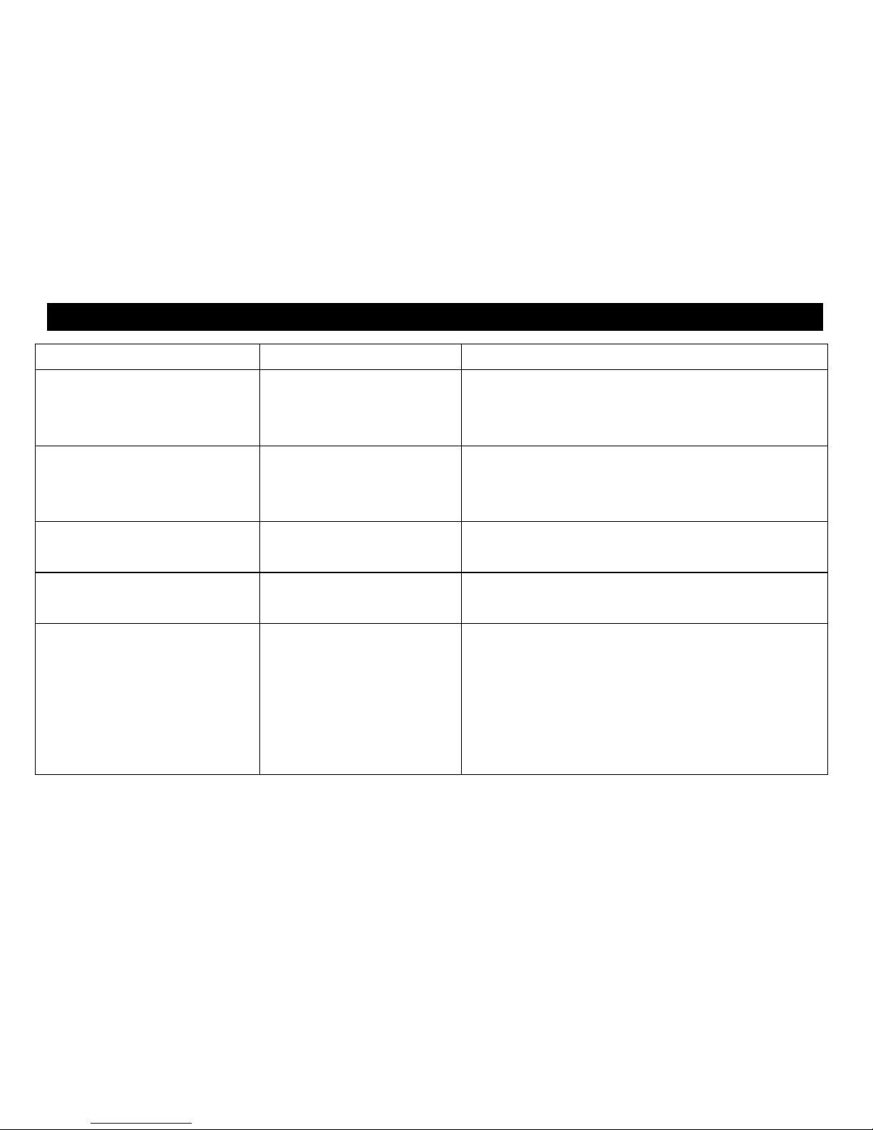
6. Troubleshooting
Faults
Possible reasons
Troubleshooting
Green indicator slowly flashing
Buzzer sounds
DC input under voltage
Measure the DC input voltage, if the voltage is lower
than 10.8/21.6/43.2V. Adjust the input voltage to
restore normally.
Green indicator fast flashing
Buzzer sounds
DC input over voltage
Measure the DC input voltage, if the voltage is
higher than 16/32/64V. Adjust the input voltage to
restore normally.
Red indicator slowly flashing
Buzzer sounds
Overload
Reduce the number of the AC load.
Restart the inverter.
Red indicator fast flashing
Buzzer sounds
Short circuit
Check carefully loads connection, clear the fault.
Restart the inverter.
Green and red indicator on
solid Buzzer sounds
Over temperature
When the heat sink temperature exceeds 80℃ or
the internal temperature exceeds 60℃, the inverter
will automatically stop output; When the heat sink
temperature below 70℃ and the internal
temperature below 50℃, the inverter will resume to
output.
Page 16

13
7. Maintenance and Warranty
The casing of the inverters may be cleaned regularly with a damp cloth (not
wet) to prevent accumulation of dust and dirt. The screws on the DC input
terminals must be tightened.
The warranty period of the inverter is two years since the date of original
shipping. Within the period, we will repair the product or replace the defective
product for free. Return the defective with shipping cost prepaid. And provide
proof of purchasing date. We will pay the return shipping charges within
warranty period.
This warranty does not apply under the following conditions:
Damage from improper use or use in an unsuitable environment.
Input voltage exceeds the rated value of inverter.
The inverter’s working temperature exceeds the limit working environment
temperature.
User disassembly or attempted repair the inverter without permission.
The inverter is damaged due to natural elements such as lightning.
The inverter is damaged during transportation and shipment.
Page 17
14
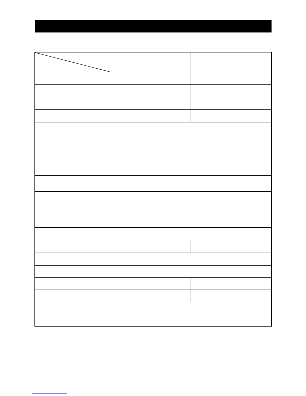
8. Technical Specification
Technical Parameters
Model
Item
IP1500-12
IP1500-22
Input Rated Voltage
12VDC
24VDC
Input Voltage Range
10.8~16VDC
21.6~32VDC
Input surge voltage
<20VDC
<40VDC
No-load current
<1.0A
<0.6A
Output Voltage
220VAC(±5%)
230VAC(-7%~+5%)
Output Continuous
Power
1200W
Output Power 15 min.
1500W
Instantaneous impact
power
2400W
Output way
Single phase
Output Wave
Pure sine wave
Output Frequency
50/60Hz(±0.2%)
Distortion THD
THD≤5%(Resistive load)
Max. Efficiency
93%
94%
Max. USB Output
5VDC/1A
Binding post
Φ10mm
Overall dimension
326.12×231.5×98.5mm
284.7×231.5×98.5mm
Mounting dimension
208×220mm
163×220mm
Mounting hole size
Φ5.5mm
Net weight
3.9kg
Page 18
15
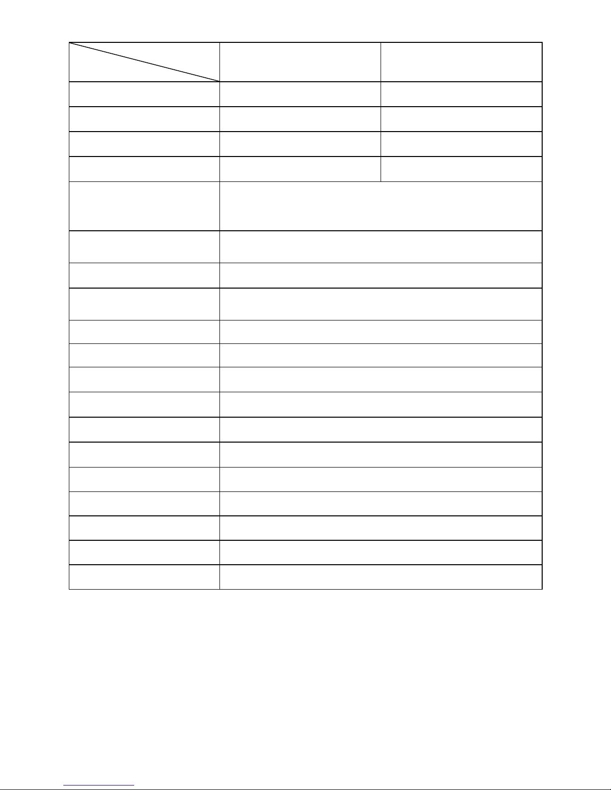
Model
Item
IP2000-22
IP2000-42
Input Rated Voltage
24VDC
48VDC
Input Voltage Range
21.6~32VDC
43.2~60VDC
Input surge voltage
<40VDC
<80VDC
No-load current
<0.6A
<0.4A
Output Voltage
220VAC(±5%)
230VAC(-10%~+5%)
Output Continuous
Power
1600W
Output Power 15 min.
2000W
Instantaneous impact
power
3200W
Output way
Single phase
Output Wave
Pure sine wave
Output Frequency
50/60Hz(±0.2%)
Distortion THD
THD≤5%(Resistive load)
Max. Efficiency
95%
Max. USB Output
5VDC/1A
Binding post
Φ10mm
Overall dimension
326.12×231.5×98.5mm
Mounting dimension
208×219.5mm
Mounting hole size
Φ5.5mm
Net weight
4.0kg
Page 19
16
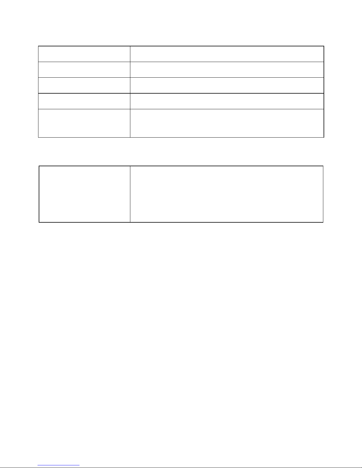
Environmental Parameters
Working Temperature
-20℃~+45℃
Storage Temperature
-35℃~ +70℃
Humidity
< 95%(N.C.)
Enclosure
IP20
Altitude
< 5000 m (Derating to operate according to
IEC62040 at a height exceeding 1000 m)
Others
Dielectric Strength
Between DC input terminals and metal case:
Test voltage AC1500V, 1 minute
Between AC output terminals and metal case:
Test voltage AC1500V, 1 minute
Any changes without prior notice! Version number:V1.0
Page 20

BEIJING EPSOLAR TECHNOLOGY CO., LTD.
Tel: +86-10-82894112 / 82894962
Fax: +86-10-82894882
E-mail:[email protected]
Website: http://www.epsolarpv.com/
http://www.epever.com/
 Loading...