

Page 1
.
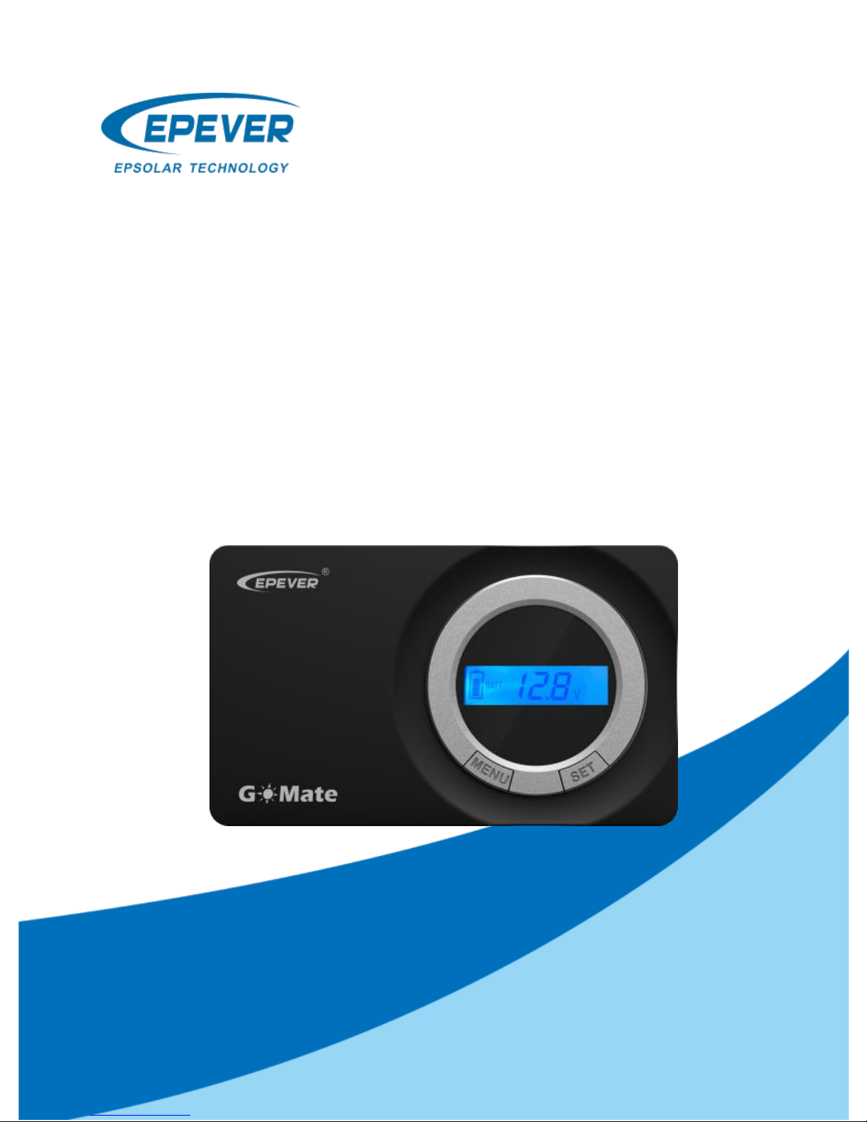
GoMate Series
——Flush Mount Solar Charger
User Manual
Model: GM3024N
Page 2

.
Page 3

.
Contents
Important Safety Instructions .................................................... 1
1. Overview ................................................................................. 2
2. Exterior .................................................................................... 3
2.1 Designations of models ............................................. 3
2.2 Accessories (Included) ............................................... 4
2.3 Accessories (Optional) ............................................... 4
3. Installation and wiring ............................................................ 5
3.1 Install the controller .................................................... 5
3.2 Wiring ........................................................................... 6
4. LCD display ............................................................................ 8
5. Protection .............................................................................. 10
6. Troubleshooting .................................................................... 11
7. Technical Specifications ...................................................... 12
8. Disclaimer ............................................................................. 14
9. Dimensions ........................................................................... 15
Page 4

BEIJING EPSOLAR TECHNOLOGY CO.,LTD.
1
Thank you for selecting the GoMate series solar charge controller.
Please read this manual carefully before using the product and pay
attention to the safety information. Please reserve this manual for
future review.
Important Safety Instructions
This manual contains all instructions of safety, installation, and operation of GoMate
series controller (“the controller” is referred to this manual).
Read all the instructions and warnings carefully before installation.
No user serviceable component inside the controller. DO NOT disassemble or
attempt to repair the controller.
Avoid direct sunlight, high temperatures and DO NOT install the controller at
locations where water can get in.
Install the controller at well-ventilated places, the controller’s heat sink will be very
hot during the system operation.
Appropriate external fuses or breakers are suggested.
Please cut off all connections of the PV array, fuses or breakers which close to the
battery before the controller installation and adjustment.
Power connections must remain tight to avoid excessive overheating from the
loose connection.
Page 5

BEIJING EPSOLAR TECHNOLOGY CO.,LTD.
2
1. Overview
The GoMate is a negative-ground, flush mount solar charge controller,
designed for an aesthetically clean and integrated look on RV and Vessel,
also included surface mount cover to suit personal preference. The
GoMate adopts highly efficient PWM charging mode, also comes
equipped with special LCD display to show the real-time operating status
of the system. This charge controller is fully controlled automatically,
which provide simple usage pattern to users.
Features:
Flush mounted and embedded installation design
High quality and low failure rate components (ST/IR) to ensure the
product lifetime
3-Stage intelligent PWM charging: Bulk, Boost/Equalize and Float
Battery type: Sealed, Gel, Flooded, and User
Real-time energy statistics feature
Battery temperature compensation feature
Digital LCD monitor for informative display of operational parameters
and fault messages
Voltage drop and temperature compensation sampling interface design
RS485 communication port with Modbus protocol, and short circuit
protection for 5V/200mA power supply
Multiple communication peripherals
Rated charging current at working temperature without de-rating
Extensive electronic protections
Monitor and set the parameters via PC software or APP
Page 6
BEIJING EPSOLAR TECHNOLOGY CO.,LTD.
3
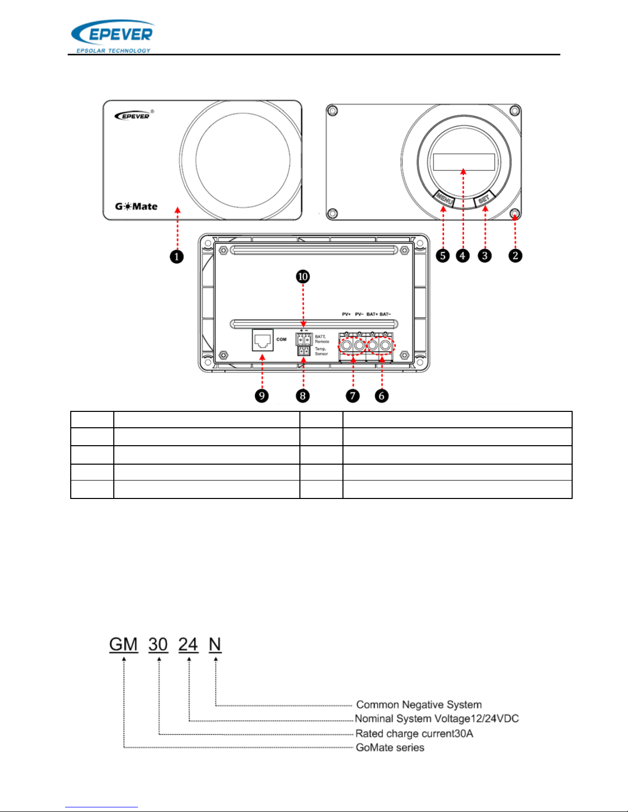
2. Exterior
❶
Controller case
❻
Battery terminals
❷
Mounting hole sizeφ 4.5mm
❼
PV terminals
❸
SET button
❽
Remote temperature sensor port⑴
❹
LCD
❾
RS485 communication port
❺
MENU button
❿
Remote battery voltage sensor port⑵
(1)The controller will charge the battery at 25℃ as default and no temperature
compensation when the temperature sensor is damaged.
(2) The port can detect accurate battery voltage(a 2P/1.5mm2 wire (Red+, black-)
with insulation protection is suggested). One end connects the 5.08-2P terminal to
insert ❿ port, the other end connects the battery, and make sure the “+” and “-”
poles are connected correctly.
2.1 Designations of models
Page 7
BEIJING EPSOLAR TECHNOLOGY CO.,LTD.
4
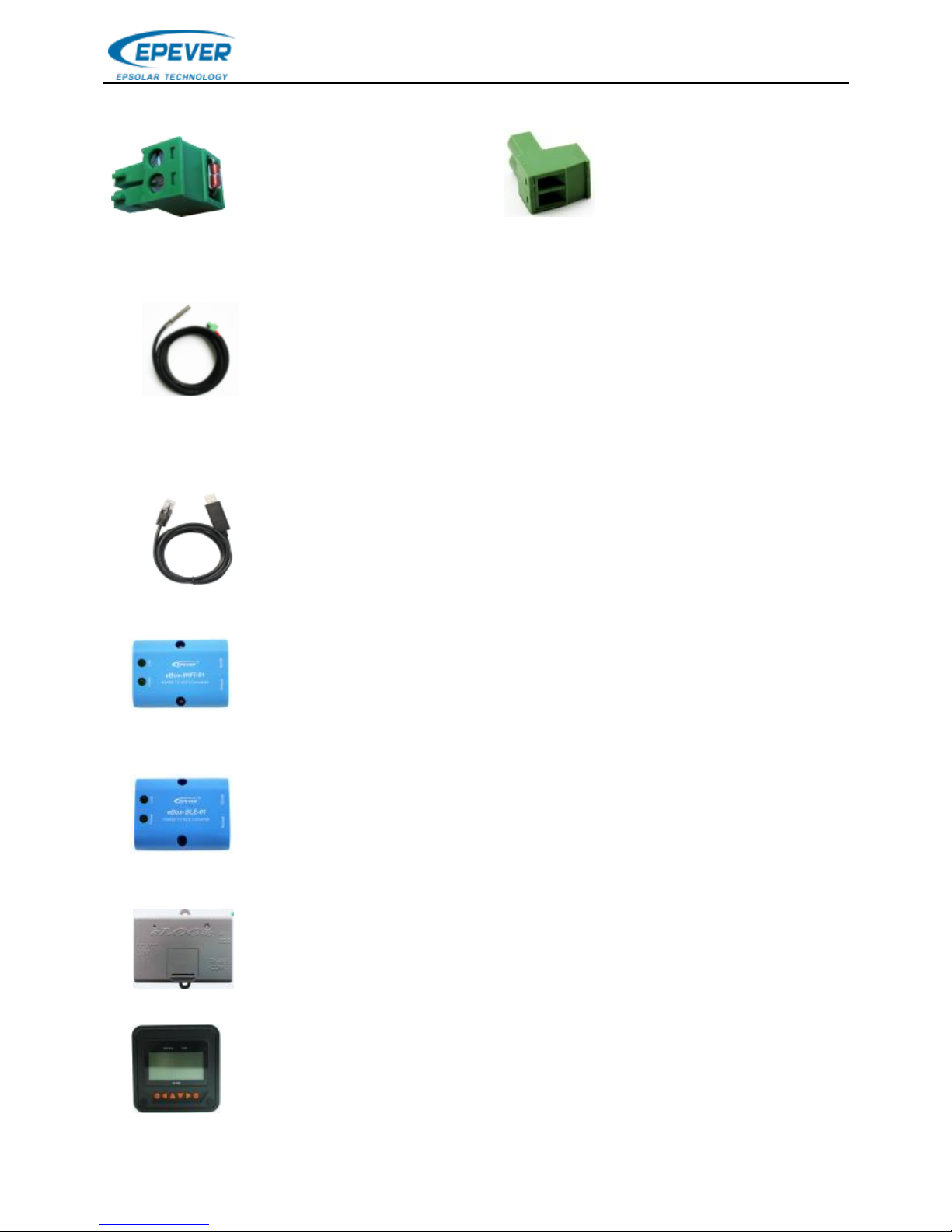
2.2 Accessories (Included)
(Model: RT-MF58R47K3.81A)
2.3 Accessories (Optional)
1)Remote Temperature Sensor(Model:RTS300R47K3.81A)
NOTE: The temperature sensor short-circuited or damaged, the controller
will be charged or discharged at the default temperature of 25 ℃.
2)USB to RS485 communication cable(Model:CC-USB-RS485-150U)
3)RS485 TO WIFI Converter (Model:eBox-WIFI-01)
4)RS485 TO BLE Converter(Model:eBox-BLE-01)
5)Logger(Model:eLOG01)
6)Remote Meter(Model:MT50)
Temperature Sensor
Acquisition of battery temperature for undertaking temperature
compensation of control parameters, the standard length of the
cable is 3m (length can be customized). The RTS300R47K3.81A
connects to the port ❽on the controller.
USB to RS485 converter is used to monitor each controller using
Solar Station PC software. The length of cable is 1.5m.
TheCC-USB-RS485-150U connects to the RS485 Port on the
After the controller is connected with the eBox-WIFI-01 through
the standard Ethernet cable (parallel cable), the operating status
and related parameters of the controller can be monitored by the
mobile APP software through WIFI signals.
After the controller is connected with the eBox-BLE-01 through
the standard Ethernet cable (parallel cable), the operating status
and related parameters of the controller can be monitored by the
mobile APP software through Bluetooth signals.
After the controller is connected with the eLOG-01 through the
RS485 communication cable, it can record the operating data of
the controller or monitor the real-time operating status of the
MT50 displays various operating data and fault info the system.
The information can be displayed on a backlit LCD screen, the
buttons are easy-to-operate, and the numeric display is readable.
5.08-2P Terminal
Page 8
BEIJING EPSOLAR TECHNOLOGY CO.,LTD.
5
3. Installation and wiring
3.1 Install the controller
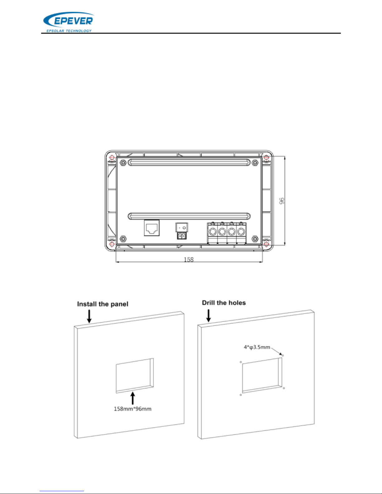
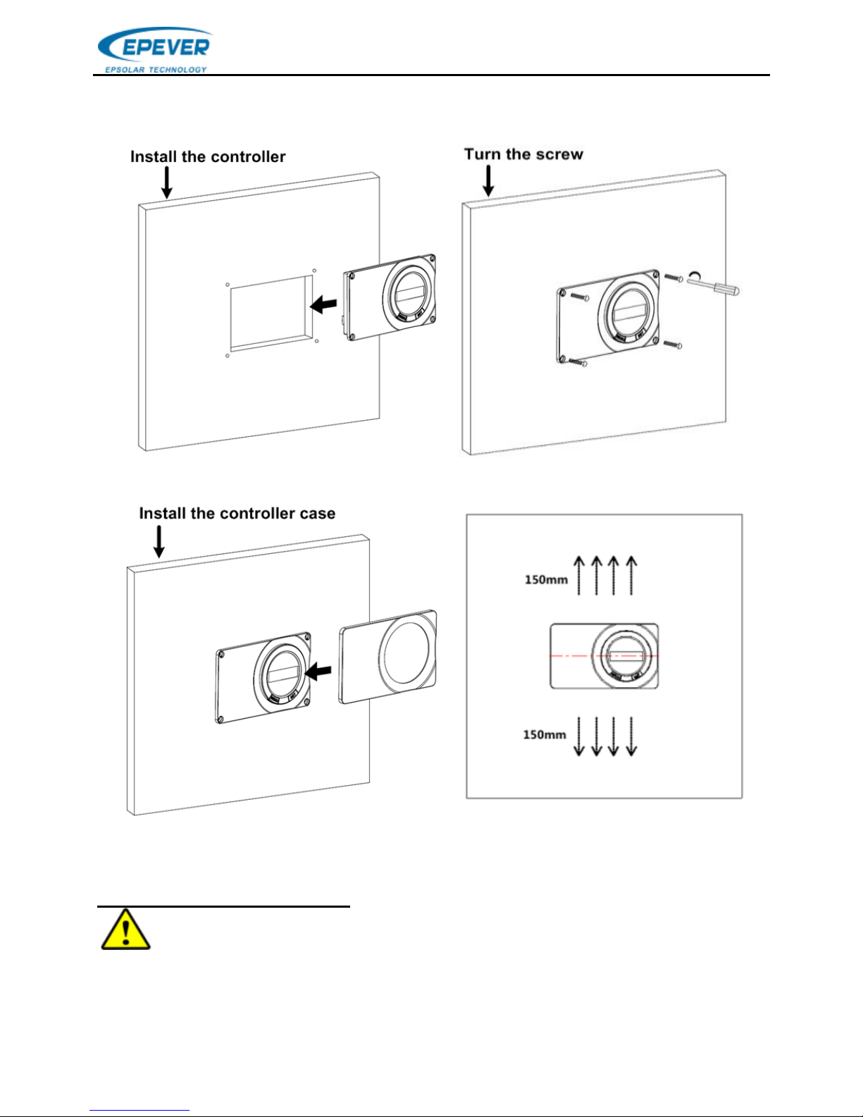
1) Determine the Installation Location and Heat-dissipation Space
Determination of installation location: The controller shall be installed in a place with
sufficient air flow through the radiators of the controller and a minimum clearance of
150 mm from the upper and lower edges to ensure natural thermal convection.
2) Determine the size of Installation Location (158*96mm)
3) Cut out the section (158*96mm)
4) Mark holes and drill holesφ 3.5mm*4
Page 9
BEIJING EPSOLAR TECHNOLOGY CO.,LTD.
6
5) Secure the controller
6) Install the control case
3.2 Wiring
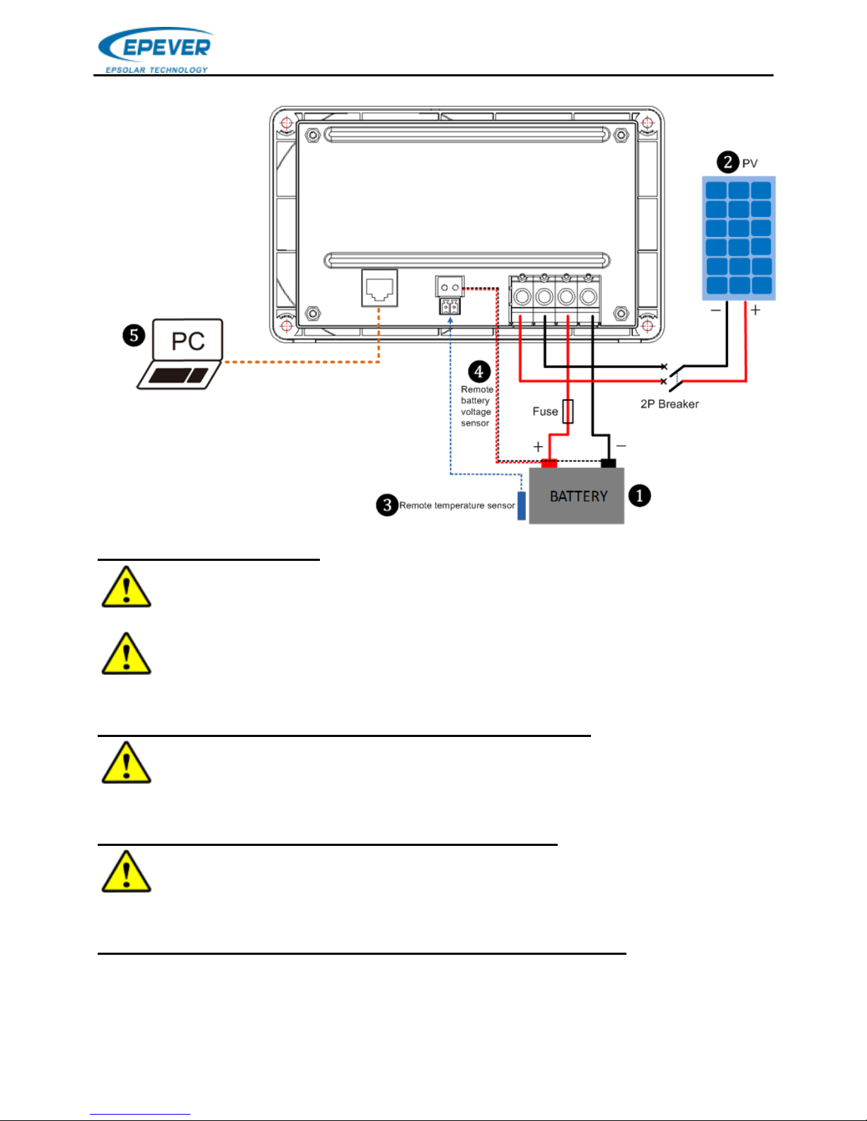
Step1: connect the battery ❶
CAUTION: A fuse which current is 1.25 to 2 times the rated current of the
controller must be installed on the battery side with a distance from the battery not
greater than 150 mm.
Page 10
BEIJING EPSOLAR TECHNOLOGY CO.,LTD.
7
Step2: Connect the PV ❷
CAUTION: While wiring the controller do not turn on the breaker or fuse and
make sure that the leads of "+" and "-" poles are connected correctly.
CAUTION: If the controller is used in the ungoverned or frequent lightning
area, must install a reasonable arrester in the PV array input side.
Step3: Connect the Remote temperature sensor cable ❸
NOTE: The controller will charge or discharge the battery at 25℃ as default
and no temperature compensation when the temperature sensor is damaged.
Step4:Connect the Remote battery voltage sensor ❹
CAUTION: Make sure that the battery voltage sensor cable of "+" and "-"
poles are connected correctly when wiring.
Step5: Connect the PC via the RS485 communication port ❺
Refer to the chapter 4 "Remote set battery type".
Page 11
BEIJING EPSOLAR TECHNOLOGY CO.,LTD.
8
4. LCD display
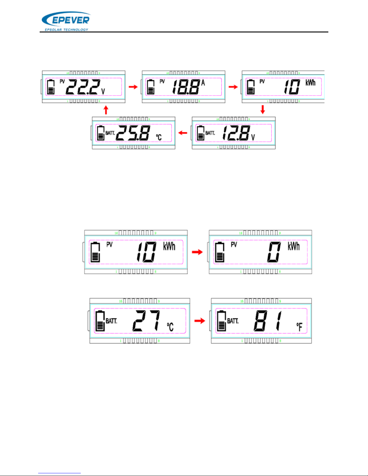
1) Automatic cycle interface
Display: PV voltage, PV current, PV power, Battery voltage and Battery temperature
2) Clear the generated energy
Operation:
Step 1: Press the “SET” button and hold 5s under the PV power interface and the
value is flashing.
Step 2: Press the “SET” button to clear the generated energy
3) Switch the battery temperature unit
Press the “SET” button and hold 5s under the battery temperature interface.
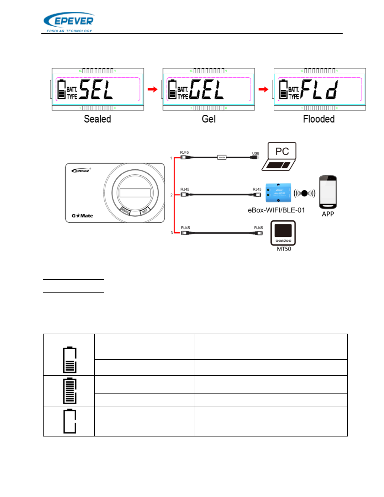
4) Battery type
Battery type
Sealed Gel Flooded User⑴
Set battery type by LCD⑴
Operation:
Step1: Press the “SET” button and hold 5s under the battery voltage interface.
Page 12
BEIJING EPSOLAR TECHNOLOGY CO.,LTD.
9
Step2: Press the “MENU” button when the battery type interface is flashing.
Step3: Press the “SET” button to confirm the battery type.
Set battery type by PC⑴
Download software
www.epever.com——Solar Station Monitor
www.epever.com——ChargeController(Sealed)
(1)Only Sealed, Gel and Flooded via the LCD, The battery type of User can be set
via the PC software, APP software and MT50.
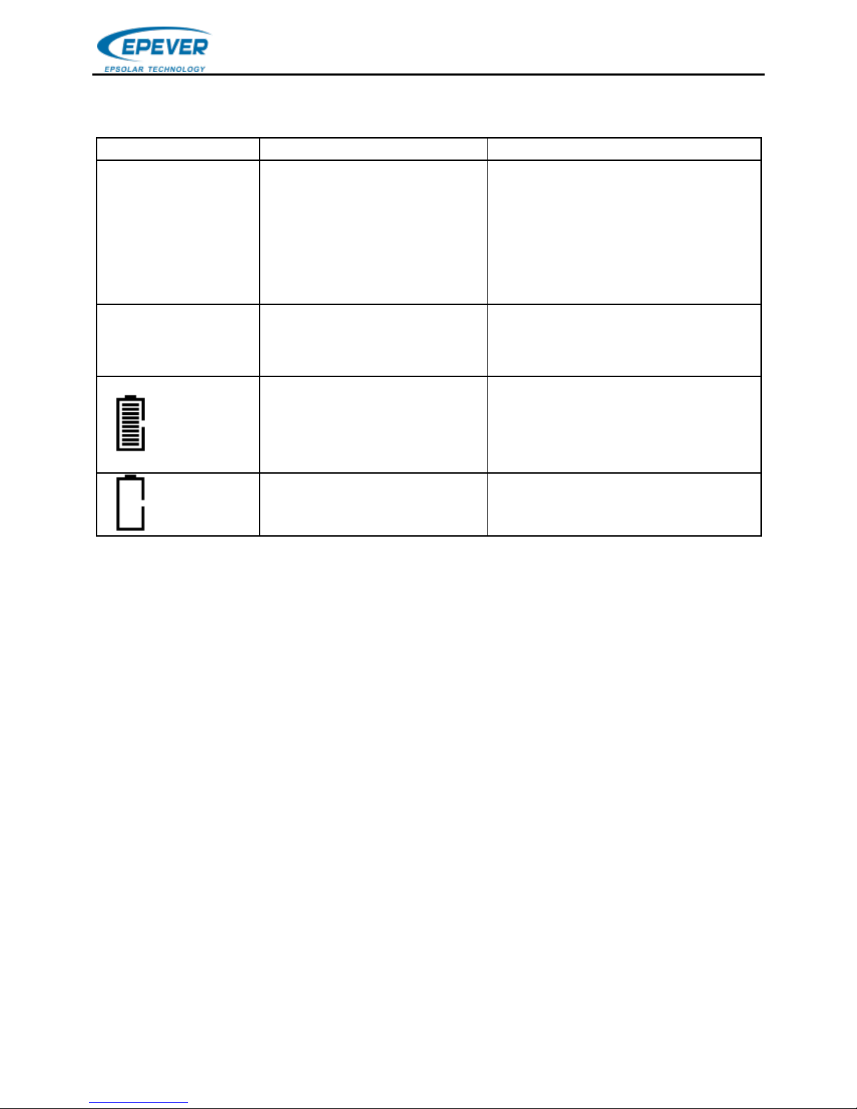
5) System status icon
Icon
Phenomenon
Instruction
Solid
The system is normal but not charging
Energy bars are Flashing
Charging
Solid
Full
Flashing
Battery Overvoltage
Flashing
Battery Over Discharge
Page 13

BEIJING EPSOLAR TECHNOLOGY CO.,LTD.
10
5. Protection
Protection
Instruction
PV Overcurrent
When the charging current of the PV array exceeds the
controller’s rated current, it will be charged at the rated
current.
PV Overvoltage
When the voltage of PV will exceed 50V, the controller will
stop charging and restart to charge when the PV voltage is
below 45V
PV short circuit
When the PV voltage is below 50V and short circuit, the
controller will stop charging; the controller restart to charge
when the fault is cleared, it doesn’t damage the controller.
PV Reverse
Polarity
When the polarity of the PV array is reversed, the
controller may not be damaged and can continue to
operate normally after the polarity is corrected.
Night Reverse
Charging
Prevents the battery from discharging to the PV module at
night.
Battery Reverse
Polarity
Fully protected against battery reverse polarity; no damage
will occur to the battery. Correct the wiring error to resume
normal operation.
Battery
Overvoltage
When the battery voltage reaches the overvoltage
disconnect voltage, it will automatically stop battery
charging to prevent battery damage caused by
over-charging.
Battery
Overheating
The controller can detect the battery temperature through
an external temperature sensor. The controller stops
working when its temperature exceeds 65 °C and restart to
work when its temperature is below 55 °C.
Controller
Overheating
The controller is able to detect the temperature inside the
battery. The controller stops working when its temperature
exceeds 85 °C and restart to work when its temperature is
below 75 °C.
TVS High
Voltage
Transients
The internal circuitry of the controller is designed with
Transient Voltage Suppressors (TVS) which can only
protect against high-voltage surge pulses with less energy.
If the controller is to be used in an area with frequent
lightning strikes, it is recommended to install an external
surge arrester.
Page 14
BEIJING EPSOLAR TECHNOLOGY CO.,LTD.
11
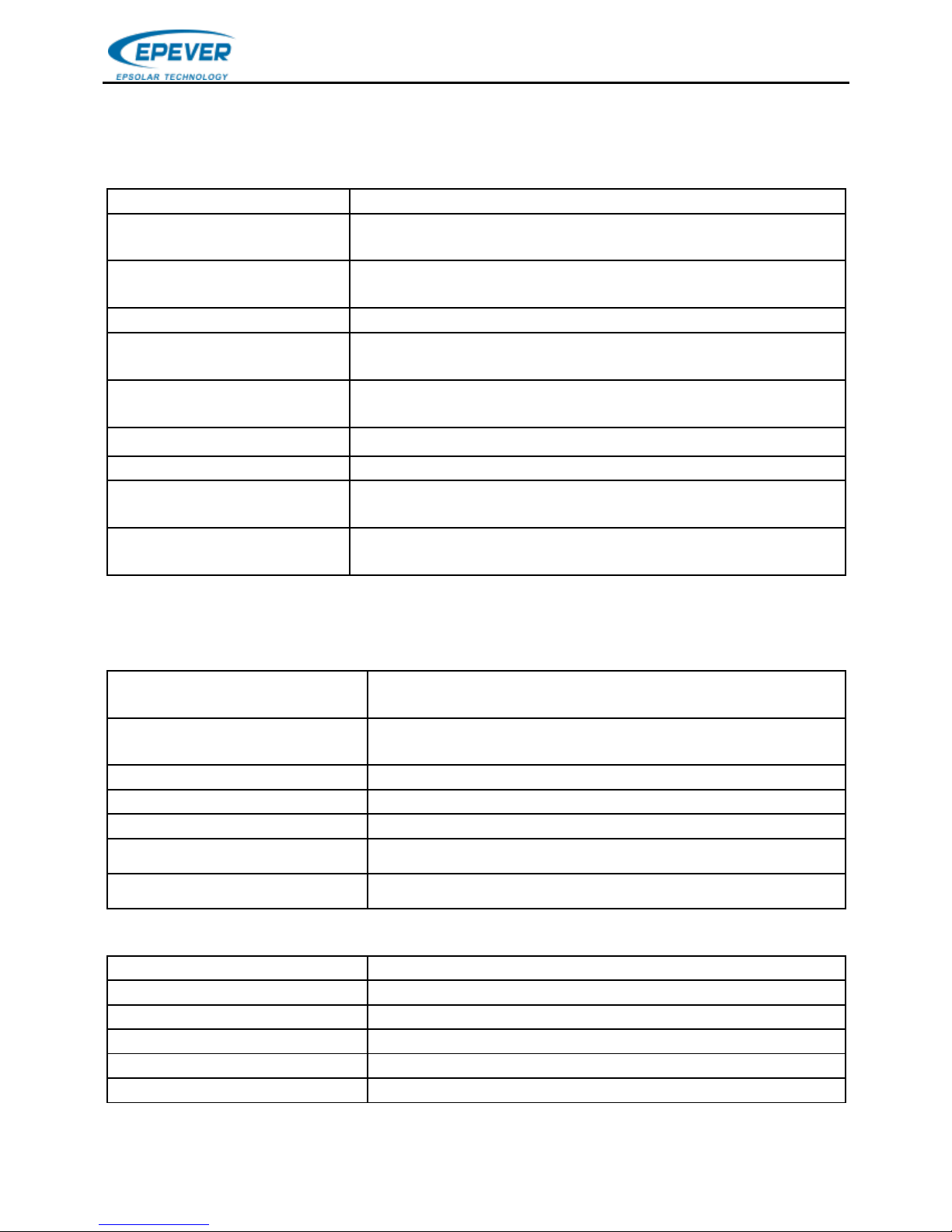
6. Troubleshooting
Faults
Possible reasons
Troubleshooting
The PV of LCD
display 0 when
the sunshine
falls on PV
modules
properly
PV array
disconnection
Confirm that PV wire
connections are correct
and tight
LCD is no
display
Min.8V will start up
the controller.
Measure battery voltage
with multi-meter. Min.8V
can start up the controller.
Flashing
Battery Overvoltage
Disconnect the solar array
and measure the battery
voltage whether is too
high;
Flashing
Battery Over
Discharge
Charge the battery
Page 15
BEIJING EPSOLAR TECHNOLOGY CO.,LTD.
12
7. Technical Specifications
Electrical Parameters
Item
GM3024N
Nominal System
Voltage
12/24VDC or Auto
Battery Input
Voltage Range
8V~32V
Rated Charge Current
30A
Max. PV Short Circuit
Current
30A
Max. PV Open
Circuit Voltage
50V
Battery Type
Sealed(default)/Gel/Flooded/User★
Self-consumption
≤4.2mA/12V;≤2.6mA/24V
Temperature
Compensate Coefficient
-3mV/℃/2V(Default)
Charge Circuit
Voltage Drop
0.21V
★The battery type of User can be set via the PC software, APP software and
MT50. Refer to table 1(Page 13).
Environmental Parameters
Storage Temperature
Range
-30℃~+80℃
Working Environment
Temperature
-20℃~+55℃(100% input and output)
Relative Humidity
≤95%, N.C.
Enclosure
IP30
Grounding
Common negative
Altitude
5000m
Pollution Degree
PD2
Mechanical Parameters
Dimension (L×W×H)
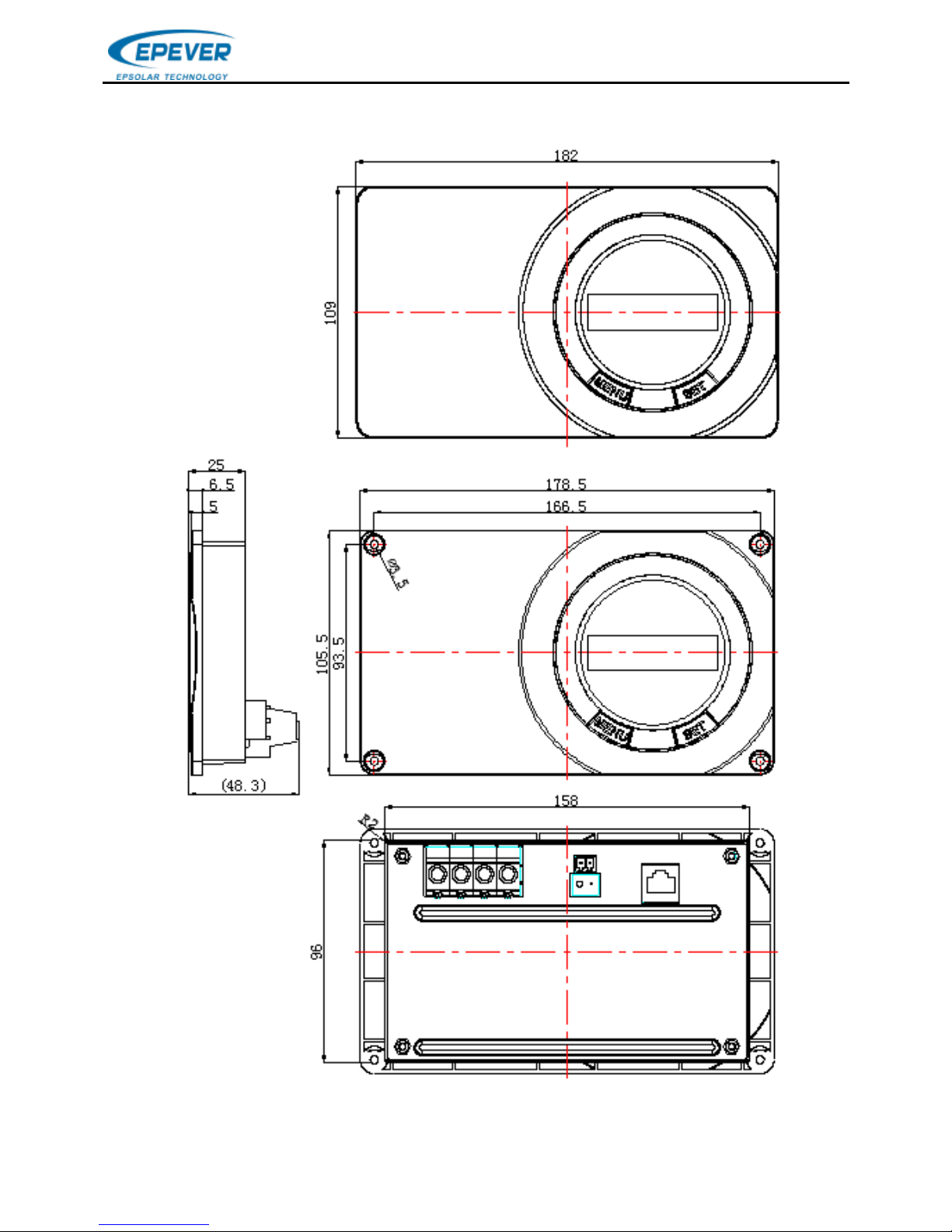
178.5×105.5×48.3mm
Mounting dimension
166.5×93.5mm
Mounting hole size
Φ5mm
Terminal
16mm2/6AWG
Recommended cable
10mm2/8AWG
Net Weight
0.31kg
Page 16

BEIJING EPSOLAR TECHNOLOGY CO.,LTD.
13
Lead-acid Battery Voltage Parameters Table1
Parameters are in the 12V system at 25℃, ×2 in 24V.
Item
Sealed
Gel
Flooded
User
Over Voltage Disconnect
Voltage
16.0V
16.0V
16.0V
9~17V
Charging Limit Voltage
15.0V
15.0V
15.0V
9~17V
Over Voltage Reconnect
Voltage
15.0V
15.0V
15.0V
9~17V
Equalize Charging
Voltage
14.6V
——
14.8V
9~17V
Boost Charging Voltage
14.4V
14.2V
14.6V
9~17V
Float Charging Voltage
13.8V
13.8V
13.8V
9~17V
Boost Reconnect
Charging Voltage
13.2V
13.2V
13.2V
9~17V
Low Voltage Reconnect
Voltage
12.6V
12.6V
12.6V
9~17V
Under Voltage Warning
Reconnect Voltage
12.2V
12.2V
12.2V
9~17V
Under Volt. Warning Volt.
12.0V
12.0V
12.0V
9~17V
Low Volt. Disconnect Volt.
11.1V
11.1V
11.1V
9~17V
Discharging Limit Voltage
10.6V
10.6V
10.6V
9~17V
Equalize Duration
120min.
——
120min.
0~180min.
Boost Duration
120min.
120min.
120min.
10~180min.
(1)When the battery type is sealed, gel, flooded, the adjusting range of equalizing
duration is 0 to180min and boost duration is 10 to180min.
(2) The battery type of User should follow the rules as below when modifying the
value of parameters in user battery type (factory default value is the same as sealed
type):
a. Over Voltage Disconnect Voltage > Charging Limit Voltage ≥ Equalize Charging
Voltage ≥ Boost Charging Voltage ≥ Float Charging Voltage > Boost Reconnect
Charging Voltage.
b. Over Voltage Disconnect Voltage > Over Voltage Reconnect Voltage
c. Low Voltage Reconnect Voltage > Low Voltage Disconnect Voltage ≥ Discharging
Limit Voltage.
d. Under Voltage Warning Reconnect Voltage > Under Voltage Warning Voltage ≥
Discharging Limit Voltage.
e. Boost Reconnect Charging voltage > Low Voltage Disconnect Voltage.
Page 17

BEIJING EPSOLAR TECHNOLOGY CO.,LTD.
14
8. Disclaimer
The following situations are not covered by the company policy of
warranty:
Damage from improper use or use in an unsuitable environment.
PV or load current, voltage or power exceeding the rated value of the
controller.
The controller working temperature exceeds the range of working
temperature.
User disassembles and attempts to repair the controller without
permission.
The controller is damaged due to natural causes such as lightning.
The controller is damaged during transportation and shipment.
Page 18
BEIJING EPSOLAR TECHNOLOGY CO.,LTD.
15
9. Dimensions
Any changes without prior notice! V1.1
Page 19

.
Page 20

.
BEIJING EPSOLAR TECHNOLOGY CO., LTD.
Tel: +86-10-82894896 / 82894112
Fax: +86-10-82894882
E-mail:[email protected]
Website: www.epever.com
 Loading...