

EP Equipment EPT20-15ET, EPT20-15ETL Service Manual
Service Manual
Electric Pallet Truck
EPT20-15ETL
EPT20-15ET
Service Manual
Electric Pallet Truck
EPT20-15ETL
EPT20-15ET

Release Date Version No. Changes (Serial number)
2016-09-27 SM-1115 09.16 New Version
This manual applies to:
Model Specifi cations
EPT20-15ET 1,500 kg Capacity
EPT20-15ETL 1,500 kg Capacity, Ultra-low Placement
Some sections of the manual only involve certain model, please refer to the manual
according to the actual confi guration of the vehicle.
*
If there are any changes, revised version will be published once every 12 months;
if there is no change, please follow the most recent version.
*
Please refer to the corresponding version of the service manual against the purchase time
of your vehicle.
*
If you need the latest versions of the manual, please contact our service department or
dealer to obtain.

EP Equipment Co., Ltd.
EP Industrial Park, Xiaquan Village,
Dipu Town, Anji County, Zhejiang Province
www.ep-zl.com
Safety signs and instructions:
Please strictly adhere to these safety instructions to avoid personal injury.
Please pay attention to the important safety instructions.
Instructions.
FOREWORD
This Service Manual can help readers learn more about the truck system components,
maintenance and troubleshooting, and other related information. The operation and
maintenance personnel must read this Manual carefully before using the product. And when
vehicle is in use, be sure to follow the complete operation and maintenance information in
this Manual for vehicle maintenance.
Before using, please check if the pages of the Manual are clear and complete, so as not
to affect your normal use because of incomplete information. If the contents of the Manual
have been illegible or damaged, which may affect reading, please contact our company or
dealer for replacement.
With the constant update and improvement of our products, the equipment you are using
may be slightly different from what has been described in this Manual, therefore, we must
reserve the right to modify the appearance, confi guration and technical specifi cations. If you
have any questions, please contact our sales department or dealer.
i
Copyright
Copyright of Service Manual belongs to
EP Equipment Co., Ltd.
REV. SM-1115 09.16

REV. 09/2016
TABLE OF CONTENTS
TABLE OF CONTENTS
1. INFORMATION & SPECIFICATIONS
..............................
1
1.1 After-sales Service Platform .........................................
3
1.2 Introduction ...................................................................
4
1.3 Common Tools ..............................................................
5
1.4 General Tightening Torques .........................................
6
2. MAINTENANCE
...............................................................
9
2.1 Overview.....................................................................
11
2.2 Maintenance ...............................................................
12
2.2.1 Cleaning ........................................................................12
2.2.2 Inspection ......................................................................12
2.2.3 Lubrication ..................................................................... 16
3. STRUCTURE & FUNCTIONS
........................................
19
3.1 Structure & Functions .................................................
21
3.1.1 Travel Switch .................................................................21
3.1.2 Lifting/Lowering Switch ..................................................21
3.1.3 Emergency Reverse Switch ..........................................21
3.1.4 Horn Switch ...................................................................21
3.1.5 Emergency Stop Switch ................................................22
3.1.6 Key Switch .....................................................................22
3.1.7 Charge Gauge ............................................................... 22
3.1.8 LED Charging Indicator .................................................22
3.1.9 Buzzer ..........................................................................23
3.1.10 Fuse.............................................................................23
3.1.11 Controller .....................................................................23
3.1.12 Charger........................................................................23
3.1.13 Lifting Limit Switch .......................................................24
3.1.14 Interlock Switch ...........................................................24
3.1.15 Pump Motor ................................................................. 24
3.1.16 Gear Pump ..................................................................24
3.1.17 Pump Contactor...........................................................25
3.1.18 Solenoid Valve .............................................................25
4. CHASSIS SYSTEM
........................................................
27
4.1 Load Wheel ................................................................
29
4.1.1 Removal and Installation ...............................................29
4.1.2 Faults and Causes.........................................................30
4.2 Cover ..........................................................................
30
4.2.1 Removal and Installation ...............................................30
SECTION
PAGE
1-5

REV. 09/2016
TABLE OF CONTENTS
4.3 Lifting Mechanism.......................................................
31
4.3.1 Fork Inspection .............................................................. 31
4.3.2 Connecting Rod Adjustment ..........................................31
4.3.3 Removal and Installation ...............................................32
5. DRIVE SYSTEM
.............................................................
33
5.1 Drive Assembly ...........................................................
36
5.1.1 Removal and Installation ...............................................36
5.2 Electromagnetic Brakes..............................................
36
5.2.1 Removal and Installation ...............................................37
5.2.2 Faults and Causes.........................................................37
5.2.3 Checking and Testing ....................................................38
5.2.4 Control Circuit Troubleshooting ..................................... 39
5.3 Drive Wheel ................................................................
40
5.3.1 Removal and Installation ...............................................40
5.3.2 Faults and Causes.........................................................40
5.4 Drive Motor .................................................................
41
5.4.1 Removal and Installation ...............................................41
5.4.2 Faults and Causes.........................................................41
5.4.3 Checking and Testing ....................................................42
5.5 Gearbox ......................................................................
43
5.5.1 Removal and Installation ...............................................43
5.5.2 Faults and Causes.........................................................43
6. OPERATING SYSTEM
...................................................
45
6.1 Control Lever ..............................................................
47
6.2 Button Switch..............................................................
47
6.2.1 Removal and Installation ...............................................47
6.2.2 Faults and Causes.........................................................48
6.2.3 Checking and Testing ....................................................48
6.2.4 Control Circuit Troubleshooting ..................................... 49
6.3 Travel Switch ..............................................................
51
6.3.1 Removal and Installation ...............................................51
6.3.2 Faults and Causes.........................................................51
6.3.3 Checking and Testing ....................................................51
6.3.4 Control Circuit Troubleshooting ..................................... 52
7. HYDRAULIC SYSTEM
...................................................
53
7.1 Overview.....................................................................
55
7.1.1 Hydraulic Schematic Diagram ......................................56
2-5
TABLE OF CONTENTS
SECTION
PAGE

REV. 09/2016
TABLE OF CONTENTS
7.2 Pump and Motor Assembly.........................................
57
7.2.1 Removal and Installation ...............................................57
7.2.2 Component .................................................................... 58
7.3 Pump Motor ................................................................
58
7.3.1 Removal and Installation ...............................................58
7.3.2 Faults and Causes.........................................................59
7.3.3 Checking and Testing ....................................................59
7.4 Pump Contactor..........................................................
60
7.4.1 Faults and Causes.........................................................60
7.4.2 Checking and Testing ....................................................61
7.4.3 Control Circuit Troubleshooting ..................................... 61
7.5 Solenoid Valve ...........................................................
62
7.5.1 Faults and Causes.........................................................62
7.5.2 Checking and Testing ....................................................62
7.5.3 Control Circuit Troubleshooting ..................................... 63
7.6 Reach Cylinder ...........................................................
64
7.6.1 Cylinder Removal Precautions ......................................64
7.6.2 Cylinder Installation Precautions ...................................65
7.6.3 Removal and Installation ...............................................66
7.7 Hydraulic Troubleshooting ..........................................
68
7.8 Hydraulic Symbol........................................................
69
8. ELECTRICAL SYSTEM
.................................................
71
8.1 Controller ....................................................................
73
8.1.1 Removal and Installation ...............................................73
8.1.2 Controller Interface Function .........................................73
8.2 Fuse............................................................................
75
8.2.1 Location of Fuses ..........................................................75
8.2.2 Checking and Testing ....................................................76
8.3 Key Switch ..................................................................
77
8.3.1 Removal and Installation ...............................................77
8.3.2 Faults and Causes.........................................................77
8.3.3 Checking and Testing ....................................................77
8.3.4 Control Circuit Troubleshooting ..................................... 77
8.4 Charge Gauge ............................................................
78
8.4.1 Removal and Installation ...............................................78
8.4.2 Faults and Causes.........................................................78
8.4.3 Checking and Testing ....................................................78
8.4.4 Control Circuit Troubleshooting ..................................... 78
8.5 LED Charging Indicator ..............................................
79
8.5.1 Removal and Installation ...............................................79
3-5
TABLE OF CONTENTS
SECTION
PAGE

REV. 09/2016
TABLE OF CONTENTS
8.5.2 Faults and Causes.........................................................79
8.5.3 Checking and Testing ....................................................79
8.5.4 Control Circuit Troubleshooting ..................................... 79
8.6 Lifting Limit Switch ......................................................
80
8.6.1 Removal and Installation ...............................................80
8.6.2 Faults and Causes.........................................................80
8.6.3 Checking and Testing ....................................................80
8.6.4 Control Circuit Troubleshooting ..................................... 80
8.7 Interlock Switch ..........................................................
81
8.7.1 Removal and Installation ...............................................81
8.7.2 Faults and Causes.........................................................81
8.7.3 Checking and Testing ....................................................81
8.7.4 Control Circuit Troubleshooting ..................................... 81
8.8 Speed Mode Switch (Optional) ...................................
82
8.8.1 Removal and Installation ...............................................82
8.8.2 Connection Mode ..........................................................82
8.8.3 Faults and Causes.........................................................82
8.8.4 Checking and Testing ....................................................82
8.8.5 Control Circuit Troubleshooting ..................................... 83
8.9 Handheld Unit (Optional) ............................................
84
8.9.1 Handheld Unit Connection.............................................84
8.9.2 Handheld Unit Main Menu .............................................84
8.9.3 Parameter Settings ........................................................85
8.9.4 TESTER Menu ..............................................................87
8.10 Controller Error Message .........................................
88
8.10.1 Traction Controller ....................................................... 88
8.11 Electrical Schematic Diagrams .................................
91
8.12 Cable Wiring Diagrams.............................................
94
8.13 Wiring Harness and Connectors...............................
95
9. TROUBLESHOOTING
...................................................
97
9.1 Preparation Before Troubleshooting ...........................
99
9.1.1 Check the Voltage of Battery .........................................99
9.2 Troubleshooting Solutions of Common Faults ..........
100
APPENDIX
................................................................
103
B SERVICE MANUAL - BATTERY
.................................
105
B1 Lead-acid Battery
......................................................
107
B1-1 Safety and Warnings ..............................................
107
4-5
TABLE OF CONTENTS
SECTION
PAGE

REV. 09/2016
TABLE OF CONTENTS
B1-2 Use of Battery ........................................................
107
B1-2.1 Pre-use Checks ........................................................107
B1-2.2 Discharging ............................................................... 107
B1-2.3 Charging ...................................................................108
B1-2.4 Temperature ..............................................................108
B1-3 Maintenance & Care .............................................
108
B1-3.1 Daily Maintenance ....................................................108
B1-3.2 Weekly Maintenance .................................................108
B1-3.3 Monthly Maintenance ................................................109
B1-3.4 Care ..........................................................................109
B1-4 Storage ..................................................................
110
B1-5 Troubleshooting .....................................................
110
B2 Maintenance-free Battery
.........................................
113
B2-1 Safety and Warnings ..............................................
113
B2-2 Use of Battery ........................................................
113
B2-2.1 Pre-use Checks ........................................................113
B2-2.2 Discharging ............................................................... 113
B2-2.3 Charging ...................................................................114
B2-3 Maintenance & Care ..............................................
114
C SCHEDULE
.................................................................
115
5-5
TABLE OF CONTENTS
SECTION
PAGE

REV. 09/2016
TABLE OF CONTENTS

SAFETY WARNING
For your own safety and that of others, please observe the following safety instructions:
Thorough and normative maintenance is one of the most important prerequisites to ensure
stable and reliable operation of truck. Neglecting regular maintenance could easily lead
to the truck malfunction and failure, and potential threats to staff and operational safety.
Therefore, there must be adequate maintenance equipment, professional maintenance
personnel and a comprehensive maintenance plan in place.
Please perform the maintenance and inspections according to the following provisions:
To strictly enforce the truck maintenance, lubrication and inspection plans.
Truck maintenance, lubrication and inspection personnel must be approved by accredited
certifi cation or evaluation agency.
The following operations shall be performed before you leave the truck:
- No parking on slopes.
- Fully lower the forks.
- Cut off the power supply.
- Turn the switch lock to “STOP” and remove the key.
Prior to truck maintenance:
- Raise the drive wheel off the ground, or cut off the power supply connection.
- Use wooden wedges or other effective fi xtures.
- When performing maintenance underneath the vehicle, make sure that the lifting device
or jack leg is secure.
- Park your vehicle in a safe and secure area.
Never use an open fl ame to check level of electrolyte, other oils or fl uids for leaks.
Keep the parking lot clean, well-ventilated and dry.
Regular checks and maintenance should be conducted to braking, steering, control, warning
and safety devices to keep them in good condition.
All nameplates and safety signs on the truck should be cleaned regularly to make them
clearly visible.
Regular checks and maintenance should be conducted to all the devices of lifting system to
ensure them to be safe for use.
The hydraulic system should be checked regularly based on usage. Hydraulic cylinders,
hydraulic valves and other hydraulic components should be ensured to be without leakage.
Regular checks and maintenance should be conducted to batteries, motors, controllers,
limit switches, protective devices, wires and connectors, and so on. Please pay particular
attention to the electrical insulation.
Park the truck in a clean environment to minimize the risk of fi re.
Without the permission of the manufacturer, users are not allowed to change or increase
the capacity of the truck. After having been changed under permission, the nameplates and
safety signs on the truck should also be changed accordingly.
1.
2.
3.
4.
5.
6.
7.
8.
9.
10.
11.
12.
13.
1
1
1. INFORMATION & SPECIFICATIONS

2
NOTE:
3
REV. 09/2016
INFORMATION & SPECIFICATIONS
1
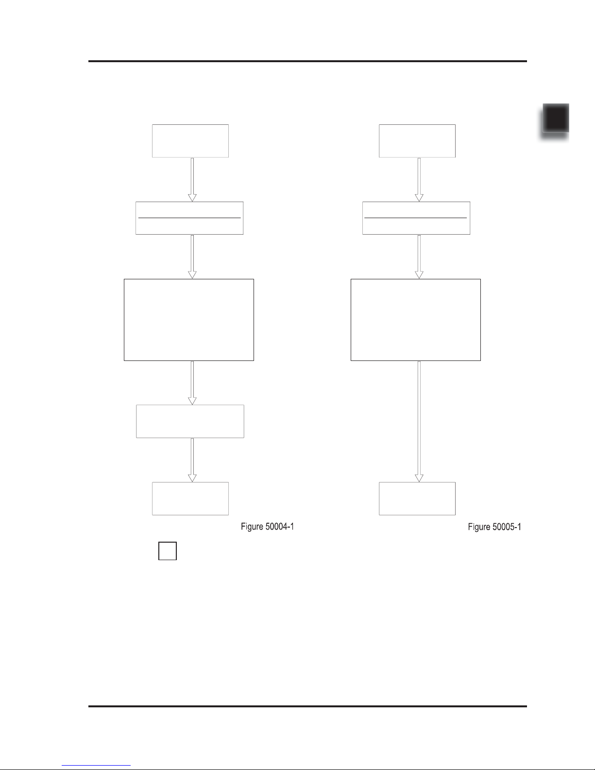
1.1 After-sales Service Platform
Claims/Replacement Parts Service Platform:
In order to provide you with a fast and effi cient
after-sales service, when you claim / order spare
parts or after-sales service upon maintenance,
please provide accurate truck model, vehicle
body serial number and part number.
After-sales Maintenance Service Platform:
Customer
nxsp@ep-zl.com
Customer
Components
Warehouse
Customer service to input
into After-sales System.
After-sale Engineer to
call back to confirm the
accuracy of the information
about the components.
Shipped within
24 hours
Claim Form
Customer service to input
into After-sales System.
After-sale Engineer to call
back to confirm about the
specifi c fault information.
Within two business
days after the maintenance, customer service
will call back and close
the claim.
Maintenance service
specialist will provide
on-site service at the
appointed time.
i
NOTE
Customer
nxsp@ep-zl.com
Claim Form
Customer
REV. 09/2016
INFORMATION & SPECIFICATIONS
1
4
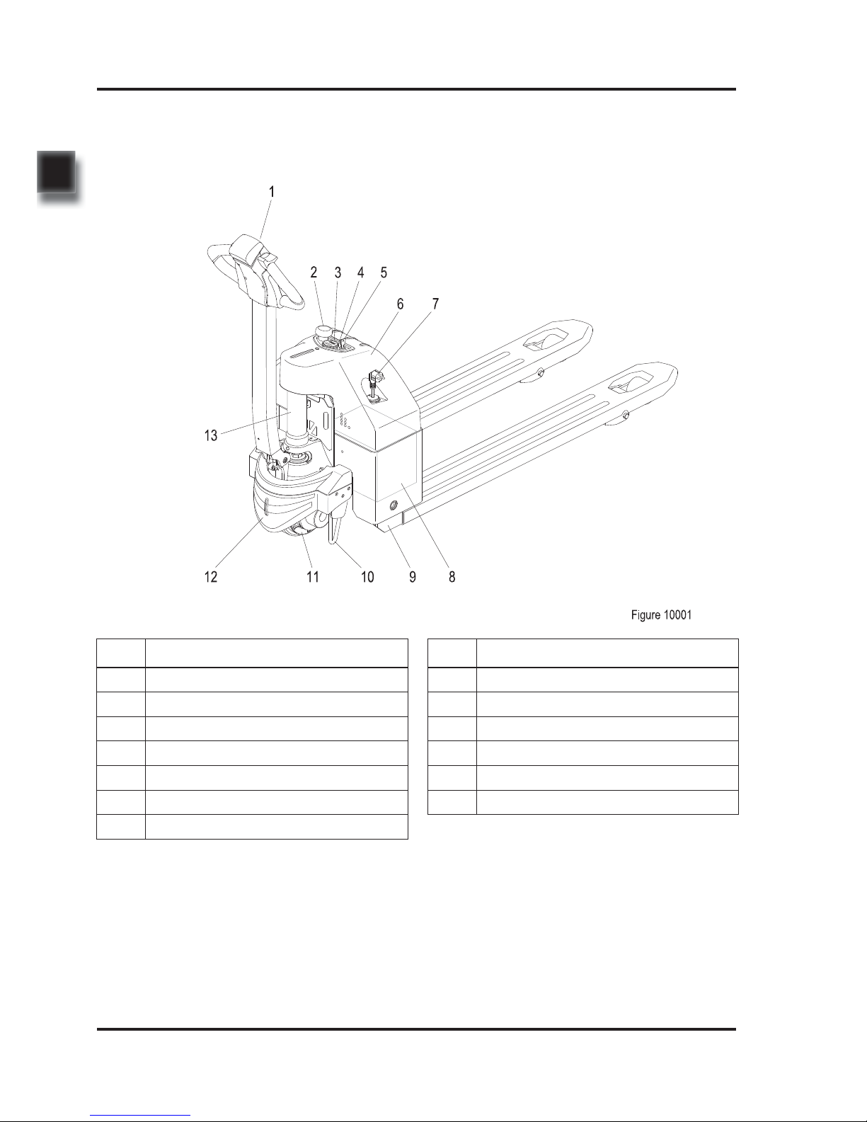
No. Name
1 Control Lever
2 Emergency Stop Switch
3 Charge Gauge
4 LED Charging Indicator
5 Key Switch
6 Upper Cover
7 Charging Plug
No. Name
8 Battery
9 Chassis
10 Balance Stand / Caster Wheel
11 Drive Wheel
12 Lower Cover
13 Lift Cylinder
1.2 Introduction
5
REV. 09/2016
INFORMATION & SPECIFICATIONS
1
This series are electric pallet trucks. Its important structure is as shown in Figure 10001.
-
Please refer to the nameplate for rated load
capacity of the vehicle.
-
The vehicle can only be used on the level gro und indoors, never use it on mezzanine or
balcony area.
WARNING
Truck can only be operated by single operator;
other personnel is forbidden from riding.
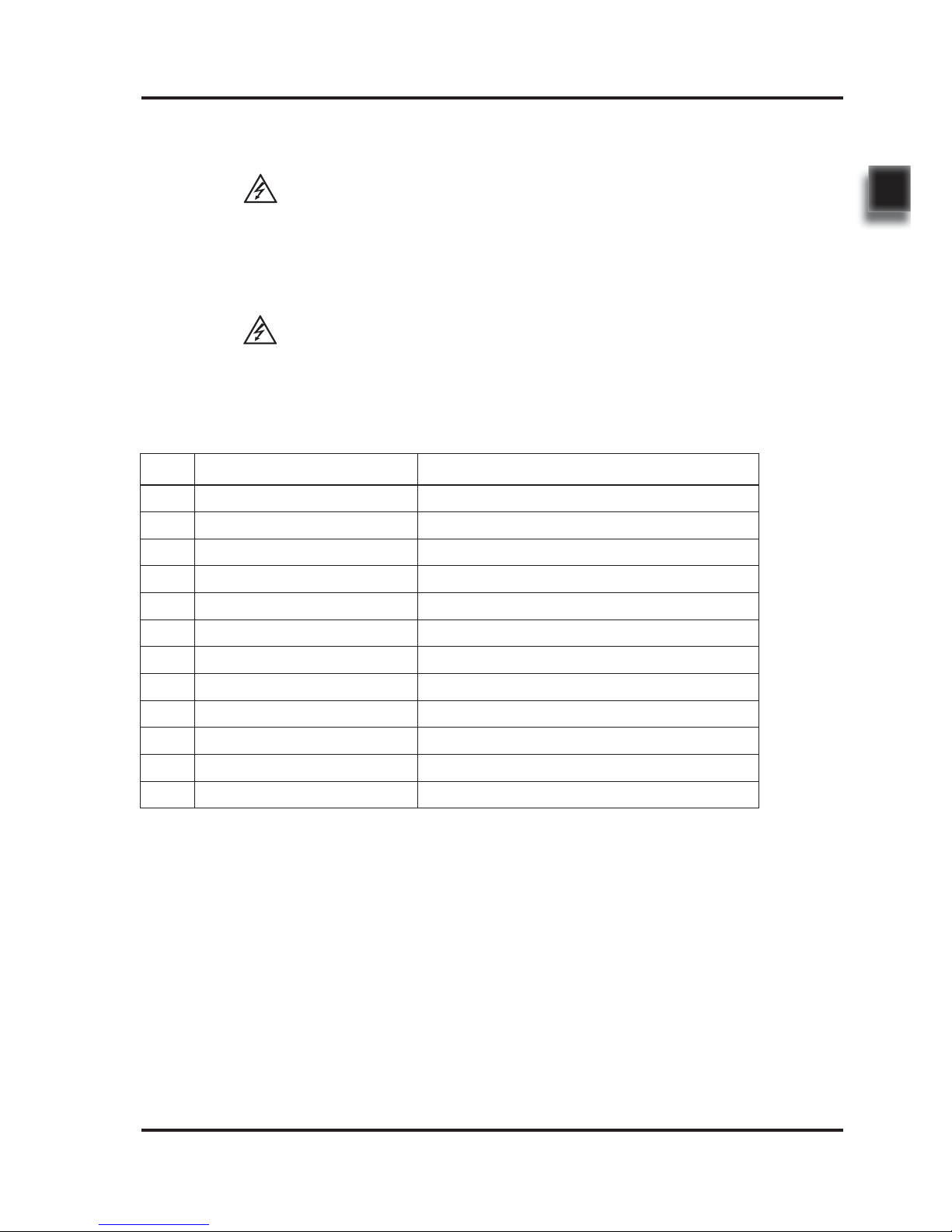
1.3 Common Tools
No. Name Remark
1 Hex Wrench 2#~14# One Set
2 Hex Head Socket Wrench 10#~27# One Set
3 Phillips Screwdriver 2# One Piece
4 Slotted Screwdriver 2# One Piece
5 Circlip Pliers One for holes and one for shaft
6 Hammer One Piece
7 Spreader, Crane One Pair
8 Cylinder Wrenches For removal and installation of cylinders
9 Diagonal Pliers One Piece
10 Cylinder Pliers One Piece
11 Grease Gun One Piece
12 Tiger Tooth Wrench 22#/27# One of Each
WARNING
REV. 09/2016
INFORMATION & SPECIFICATIONS
1
6
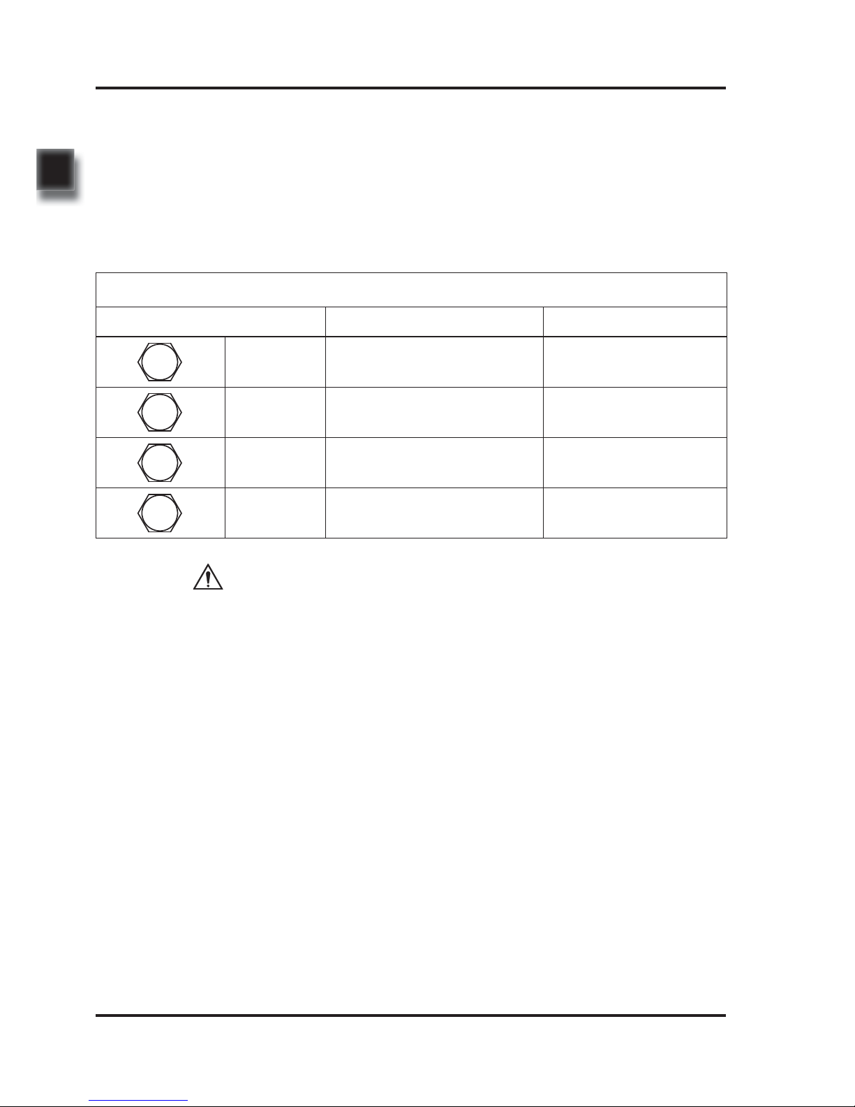
Table 1.4.1 Screws/Bolts Performance Levels
Performance Level Material Specifi cation (mm)
5.8 grade Low carbon steel M6 ~ M48
8.8 grade
Quenched and tempered medium
carbon steel
M6 ~ M48
10.9 grade
Quenched and tempered medium
carbon alloy steel
M6 ~ M48
12.9 grade
Quenched and tempered medium
carbon alloy steel
M6 ~ M48
12.9
10.9
8.8
5.8
1.4 General Tightening Torques
Screws or bolts used on the truck are of 8.8
grade or higher performance level.
When you are conducting truck maintenance,
you can refer to Table 1.4.1 and Table 1.4.2 to
select the suitable screws or bolts for replacement.
-
-
CAUTION
The performance levels of screws or bolts are
marked on the heads of the screws or bolts.
If you fi nd the screws or bolts used on certain
position are not marked with performance
level, please select spare parts with performance level of at least 8.8 grade or higher level
forreplacement.
7
REV. 09/2016
INFORMATION & SPECIFICATIONS
1
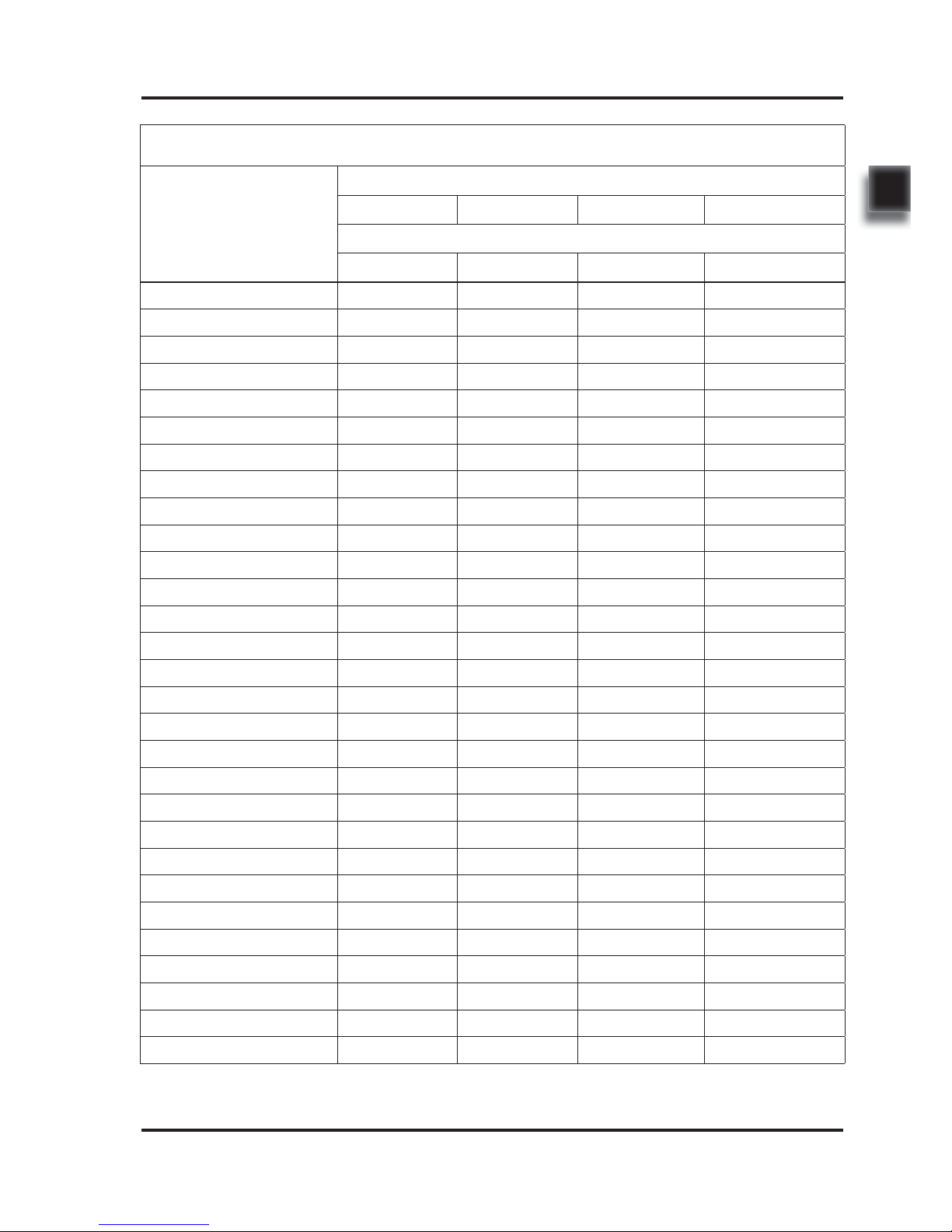
Table 1.4.2 Metric Screws/Bolts Tightening Torque Table (n•m)
Nominal Diameter
(mm)
Performance Level
5.8 8.8 10.9 12.9
Proof Stress (MPa)
380 600 830 970
M6 7~8 10~12 14~17 17~20
M8 16~18 25~30 34~41 41~48
M8×1 17~20 27~32 37~43 43~52
M10 31~36 49~59 68~81 81~96
M10×1 35~41 55~66 76~90 90~106
M12 55~64 86~103 119~141 141~167
M12×1.5 57~67 90~108 124~147 147~174
M14 87~103 137~164 189~224 224~265
M14×1.5 144~170 149~179 206~243 243~289
M16 136~160 214~256 295~350 350~414
M16×1.5 144~170 228~273 314~372 372~441
M18 186~219 294~353 406~481 481~570
M18×1.5 210~247 331~397 457~541 541~641
M20 264~312 417~500 576~683 683~808
M20×1.5 294~345 463~555 640~758 758~897
M22 360~431 568~680 786~941 918~1099
M22×1.5 395~473 624~747 803~1034 1009~1208
M24 457~547 722~864 998~1195 1167~1397
M24×2 497~595 785~940 1086~1300 1269~1520
M27 669~801 1056~1264 1461~1749 1707~2044
M27×2 723~865 1141~1366 1578~1890 1845~2208
M30 908~1087 1437~1717 1984~2375 2318~2775
M30×2 1005~1203 1587~1900 2196~2629 2566~3072
M36 1587~1900 2506~3000 3466~4150 4051~4850
M36×3 1680~2011 2653~3176 3670~4394 4289~5135
M42 2538~3039 4088~4798 5544~6637 6479~7757
M42×3 2731~3269 4312~5162 5965~7141 6921~8345
M48 3813~4564 6020~7207 8327~9969 9732~11651
M48×3 4152~4970 6556~7848 9069~10857 10598~12688

REV. 09/2016
INFORMATION & SPECIFICATIONS
1
8
9
2
2. MAINTENANCE

10
NOTE:
11
REV. 09/2016
MAINTENANCE
2
-
-
-
Working conditions:
-
-
-
2.1 Overview
Only by performing regular vehicle maintenance
and repair, can ensure the continuous and
reliable use of the truck.
Only specially trained and qualified personnel
are capable of maintenance and repair
operations of the equipment. If you want to
perform the maintenance and repair on your
own, it is recommended that on-site training
should be conducted to your maintenance
personnel by the service representative of the
vendor.
When lifting load components or during the
operations under the cabin, sufficiently strong
chains or safety device must be used to secure
the vehicle.
Truck must be parked on the level ground
reserved for maintenance (such area needs
to be clean and with less dust), block the
wheels with wooden wedges, disconnect
the key switch and disconnect the battery
connections.
When lifting the truck, the lifting tools can
only be installed on the fixed positions as
specifi ed.
When jacking up the truck, appropriate tools,
such as wedge blocks, wooden blocks, and
so on, must be used to secure the truck to prevent the occurrence of accidental rolling or
tipping over.
Without the supplier's consent, it is strictly
forbidden to make modifi cations to truck, espe-
cially to the safety devices. It is strictly forbidden
to change the various working speeds of the
truck.
Under harsh working conditions: such as, the
external temperature is too high or too low,
dusty, or implementing multiple shifts per day,
the maintenance and care interval should be
shortened.
Prior to lubrications, replacement of fi lters or
operating the hydraulic system, please clean
the external parts carefully and use a clean
container.
Only compliant lubricants can be used See
Table 2.2 Lubricants.
WARNING
CAUTION
i
NOTE
12
REV. 09/2016
MAINTENANCE
2
-
-
-
-
2.2 Maintenance
2.2.1 Cleaning
Do not use flammable liquids to clean the
truck.
Before starting to clean, all necessary
security measures must be taken to prevent
sparking (short circuit) during operation. If the
truck is powered by battery, battery plug must
be pulled out.
When cleaning electrical and electronic components, you should use low-intensity suction
gas or compressed dry air. Meanwhile, clean
the dust on the surface of components with
non-conductive and antistatic brush.
Do not use vapor steam to clean the equipment.
2.2.2 Inspection
Regular inspection and maintenance under
normal conditions of use:
Operating
Hours (h)
Requirements
50 At least once per 7 days
250 At least once per 60 days
500 At least once per 90 days
1000 At least once every 6 months
2000 At least once per year
When the truck is at running-in phase (after
approximately 100 hours of operation), the
equipment user must check the fastening of
wheel nuts and bolts and re-tighten them if
necessary.
Regular inspection and maintenance under
harsh conditions of use:
Under harsh working conditions, especially:
-
Dusty environment
-
Corrosive environment
-
Cold storage environment
The maintenance intervals should be shortened
by half.
CAUTION
13
REV. 09/2016
MAINTENANCE
2
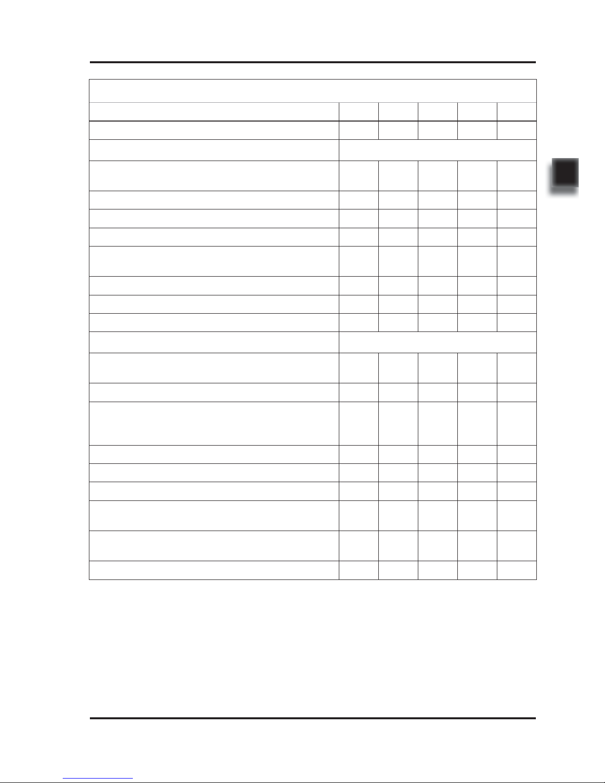
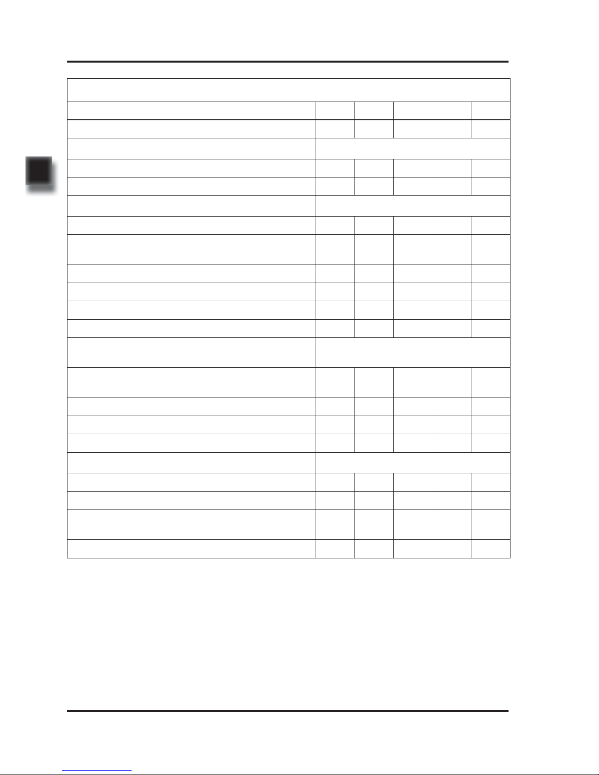
Table 2.1 Inspection & Maintenance List
Interval in days/months/years 7 d 60 d 90 d 6 m 1y
Interval in hours 50 250 500 1000 2000
Functions and Control
Check the functions of the operation switches and
display
A
Check alarm system functions A
Check interlock switch functions A
Check the emergency switch functions A
Check the cables for damage and if the terminals are
secure
A
Check the lifting limit switch functions A
Check and tighten the controllers and contactors A
Check fault information records and operating hours A
Power Supply & Drive System
Check the battery cables for damage and replace if
necessary
A
Check the battery charge connector A
Check if the cable connections between battery monomers are secure, apply some grease to electrodes if
necessary
A
Check the position of various bearings for noise A
Clean or add the gear grease A / L
Check the gearbox for abnormal noise or leaks A
Check and lubricate the bearings between drive motor
and gearbox
A / L
Check the drive wheel and load wheel for worn or
damage
A
Check the wheel bearings and fi xation A
A = Check / Adjust
Please refer to Inspection & Maintenance List
for regular inspection and maintenance of the
vehicles.
L = Lubrication
Under harsh conditions, the lubrication intervals
should be shortened by half.
14
REV. 09/2016
MAINTENANCE
2
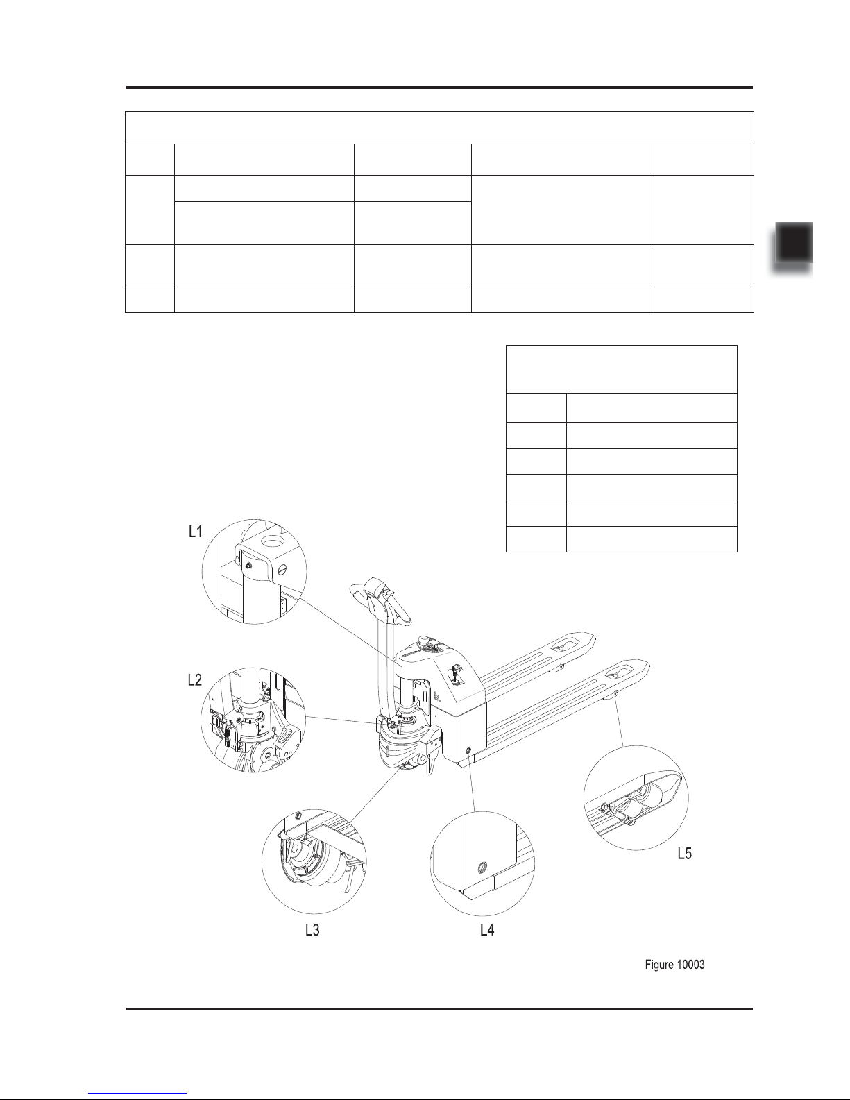
Table 2.1 Inspection & Maintenance List (Continued)
Interval in days/months/years 7 d 60 d 90 d 6 m 1y
Interval in hours 50 250 500 1000 2000
Power Supply & Drive System
Check the bearing bridge for damage or crack A
Check the travel speed A
Hydraulic System
Check the functions of hydraulic system A
Check if the hoses, pipes and interfaces are fastened
or sealed securely, and check if there is damage
A
Check the cylinders for leaks A
Check the cylinders for damages and check the fi xation A
Check the oil tank fi xation and check for leaks A
Check the hydraulic oil level A
Clean or replace the hydraulic oil
Replace after 100 hours of early operation.
Then replace once every 2000 hours
Check the function of emergency pressure relief
valve
A
Check and clean oil tank air fi lter A
Replace the oil tank air fi lter and fi lter A
Check the relief pressure A
Breking System
Check the braking functions of electromagnetic brake A
Check the air gap of electromagnetic brake A
Check the installation and connection of electromagnetic brake
A
Check the braking distance of electromagnetic brake A
A = Check / Adjust
Please refer to Inspection & Maintenance List
for regular inspection and maintenance of the
vehicles.
L = Lubrication
Under harsh conditions, the lubrication intervals
should be shortened by half.

15
REV. 09/2016
MAINTENANCE
2
Table 2.1 Inspection & Maintenance List (Continued)
Interval in days/months/years 7 d 60 d 90 d 6 m 1y
Interval in hours 50 250 500 1000 2000
Lifting Mechanism
Check the connecting rod mechanism for wear or
damage
A
Check whether the pin shaft is fi xed securely A
Check and lubricate the moving parts of connecting
rod mechanism
A / L
Check the lifting and lowering speed A
Other
Check if the signs are clear and complete A
Check the chassis for cracks or damages A
Check the connections of bolts and nuts A
Checking covering parts for damages A
Check if the optional features are functioning properly A
A = Check / Adjust
Please refer to Inspection & Maintenance List
for regular inspection and maintenance of the
vehicles.
L = Lubrication
Under harsh conditions, the lubrication intervals
should be shortened by half.
16
REV. 09/2016
MAINTENANCE
2
-
-
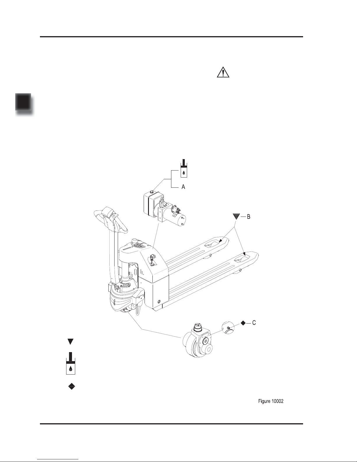
2.2.3 Lubrication
Improper operations may constitute hazards
to the operator's health and life, as well as to
the surrounding environment.
When storing or adding lubricant, use clean
containers. It is strictly forbidden to mix
different types and specifi cations of lubricants
with each other (except for those can be
mixed under clear statement).
The use and disposal of lubricants must be
carried out in strict accordance with the manufacturer's regulations.
Lubricant
Please see Table 2.2 for the lubricants used in
this truck.
Sliding surface
Hydraulic oil injection nozzle
Gear oil injection nozzle
CAUTION
17
REV. 09/2016
MAINTENANCE
2
Table 2.2 Lubricants
Code Type Specifi cation Amount Position
A
Anti-wear hydraulic oil L-HM46
0.65 L
Hydraulic
System
Low temperature anti-wear
hydraulic oil (cold storage)
L-HV32
B
Multi-purpose grease Polylub GA352P Appropriate amount
Sliding surface
(See Table 2.3)
C
Grease (MoS2) - 100 grams Gearbox
Table 2.3 Sliding Surface
Lubrication Table
Code Position
L1 Mounting Shaft
L2 Steering Bearing
L3 Drive Wheel
L4 Long Shaft
L5 Load Wheel

18
REV. 09/2016
MAINTENANCE
2
19
3
3. STRUCTURE & FUNCTIONS
 Loading...