


2−line filters
SIFI−H for very high insertion loss
250 V, 50/60 Hz, 3 ... 36 A
Ordering code: B84113H0000B030 ... G136
Date: 2006−10−10
Version: 02
EPCOS AG 2006. Reproduction, publication and dissemination of this data sheet, enclosures hereto and the
information contained therein without EPCOS’ prior express consent is prohibited.
2−line filters B84113H0000B030 ... G136
SIFI−H for very high insertion loss
Construction
2−line filter
Metal case
Polyurethane potting (UL 94 V−0)
Features
Low leakage current
Compact design
Cost optimized construction
ENEC−, UL− and CUL−approval
c
us
Applications
Switch−mode power supplies in
−industrial electronics
−telecommunications
−data systems
−medical engineering
Terminals
Case style B: Tab connectors for filters up to 16A
Mounting tabs on face ends
Case style G: Screw thread M5 for filters from 20A to 36A
Marking
Marking on component:
manufacturer’s logo, ordering code, rated voltage, rated current,
rated temperature, climatic category, date code
Minimum marking on packaging: maufacturer’s logo, ordering code
Please read Important notes and Cautions and
warnings
at the end of this document.
Page 2 of 11
B84113−H−B30 ... G136−02−7659
2−line filters B84113H0000B030 ... G136
SIFI−H for very high insertion loss
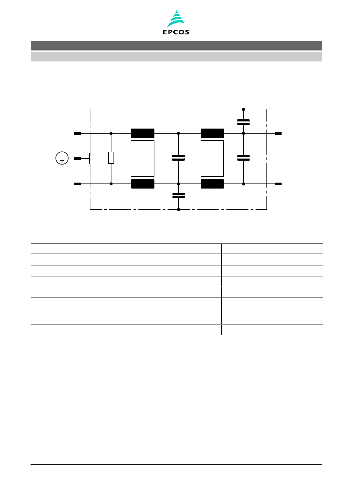
Typical circuit diagram
LINE LOAD
L
N
L’
N’
Technical data and measuring conditions
Rated voltage U
R
250 V AC
Rated frequency f
R
50/60 Hz
Test voltage line to line for 2 s U
test
1414 V DC
Test voltage line to case for 2 s U
test
2700 V DC
Rated temperature T
R
40 °C
Overload capability (thermal)
for 3 min per hour or
for 30 s per hour
1.5 x I
R
2.5 x I
R
Climatic category (IEC 60068−1) 25/100/21
Please read Important notes and Cautions and
warnings
at the end of this document.
Page 3 of 11
B84113−H−B30 ... G136−02−7659

2−line filters B84113H0000B030 ... G136
SIFI−H for very high insertion loss
Characteristics and ordering codes
I
R
C
R
L
R
I
leak
2)
Case
style
Approx.
weight
Ordering code Approvals
A mH mA g
3 2 x 1,0 µF (X2)
+
2 x 4700 pF (Y2)
4 x 5,9 < 0,5 1 250 B84113H0000B030
X X X
6 2 x 1,0 µF (X2)
+
2 x 4700 pF (Y2)
4 x 3,6 < 0,5 1 260 B84113H0000B060
X X X
10 2 x 1,5 µF (X2)
+
2 x 4700 pF (Y2)
4 x 3,9 < 0,5 2 420 B84113H0000B110
X X X
16 2 x 1,5 µF (X2)
+
2 x 4700 pF (Y2)
4 x 1,3 < 0,5 2 440 B84113H0000B116
X X X
20 2 x 2,2 µF (X2)
+
2 x 22 nF (Y2)
4 x 1,2 < 3,5 3 860 B84113H0000G120
X X X
25 2 x 2,2 µF (X2)
+
2 x 22 nF (Y2)
4 x 0,8 < 3,5 3 870 B84113H0000G125
X X X
36 2 x 3,3 µF (X2)
+
2 x 22 nF (Y2)
4 x 0,5 < 3,5 3 870 B84113H0000G136
X X X
X = approval granted
2) maximum voltage = UR; frequency = 50 Hz without harmonics; tolerance of capacitors −20%/ 0%; worst case positioning of the components
Please read Important notes and Cautions and
warnings
at the end of this document.
Page 4 of 11
B84113−H−B30 ... G136−02−7659

2−line filters B84113H0000B030 ... G136
SIFI−H for very high insertion loss
Dimensional drawing (case style 1)
B84113H0000B030...B84113H0000B060
Please read Important notes and Cautions and
warnings
at the end of this document.
Page 5 of 11
B84113−H−B30 ... G136−02−7659

2−line filters B84113H0000B030 ... G136
SIFI−H for very high insertion loss
Dimensional drawing (case style 2)
B84113H0000B110...B84113H0000B116
Please read Important notes and Cautions and
warnings
at the end of this document.
Page 6 of 11
B84113−H−B30 ... G136−02−7659

2−line filters B84113H0000B030 ... G136
SIFI−H for very high insertion loss
Dimensional drawing (case style 3)
B84113H0000G120...B84113H0000G136
Please read Important notes and Cautions and
warnings
at the end of this document.
Page 7 of 11
B84113−H−B30 ... G136−02−7659

2−line filters B84113H0000B030 ... G136
SIFI−H for very high insertion loss
Insertion loss (typical values at Z = 50 Ω)
symmetrical (differential mode)
asymmetrical, all branches in parallel (common mode)
unsymmetrical, adjacent branches terminated
B84113H0000B110
f
10
4
10
5
10
6
10
7
10
8
Hz
e
dB
0
20
40
60
80
100
B84113H0000B116
f
10
4
10
5
10
6
10
7
10
8
Hz
e
dB
0
20
40
60
80
100
B84113H0000B060
f
10
4
10
5
10
6
10
7
10
8
Hz
e
dB
0
20
40
60
80
100
B84113H0000B030
f
10
4
10
5
10
6
10
7
10
8
Hz
e
dB
0
20
40
60
80
100
Please read Important notes and Cautions and
warnings
at the end of this document.
Page 8 of 11
B84113−H−B30 ... G136−02−7659

2−line filters B84113H0000B030 ... G136
SIFI−H for very high insertion loss
Insertion loss (typical values at Z = 50 Ω)
symmetrical (differential mode)
asymmetrical, all branches in parallel (common mode)
unsymmetrical, adjacent branches terminated
B84113H0000G136
f
10
4
10
5
10
6
10
7
10
8
Hz
e
dB
0
20
40
60
80
100
B84113H0000G125
f
10
4
10
5
10
6
10
7
10
8
Hz
e
dB
0
20
40
60
80
100
B84113H0000G120
f
10
4
10
5
10
6
10
7
10
8
Hz
e
dB
0
20
40
60
80
100
Please read Important notes and Cautions and
warnings
at the end of this document.
Page 9 of 11
B84113−H−B30 ... G136−02−7659

2−line filters B84113H0000B030 ... G136
SIFI−H for very high insertion loss
Caution and warnings
Please note the advices in our data book “EMC Filters” (latest edition); attention should
be paid to the chapter “General safety notes”.
It shall be ensured that only qualified persons (electricity specialists) are engaged on work
such as planning, assembly, installation, operation, repair and maintenance. They must
be provided with the corresponding documentation.
Danger of electric shock. EMC filters contain components that store an electric charge.
Dangerous voltages can continue to exist at the filter terminals for longer than five minutes even after the power has been switched off.
The protective earth connections shall be the first to be made when the EMC filter is
installed and the last to be disconnected. Depending on the magnitude of the leakage currents, the particular specifications for making the protective−earth connection must be observed.
Impermissible overloading of the EMC filter, such as with circuits able to cause reso-
nances, impermissible voltages at higher frequencies etc. can lead to bodily injury and
death as well as cause substantial material damages (e.g. destruction of the filter housing).
EMC filters must be protected in the application against impermissible exceeding of the
rated currents by overcurrent protective.
In case of leakage currents > 3.5 mA you shall mount the PE conductor stationary with
the required cross section before beginning of operation and save it against disconnecting. For leakage currents IL
4)
< 10 mA the PE conductor must have a KU value
3)
of 4.5;
for leakage currents IL 10 mA the PE conductor must have a KU value of 6.
3) The KU value (symbol KU) is a classification parameter of safety−referred failure types designed to ensure protection against hazardous
body currents and excessive heating.
A value of KU = 4.5 with respect to interruptions is attained:
− with a permanently connected protective earth circuit 1.5 mm
2
− with a protective earth circuit 2.5 mm2 connected via shroud connectors (IEC 60309−2).
KU = 6 with respect to interruptions is achieved for fixed−connection lines 10 mm2 where the type of connection and line layout correspond to the requirements for PEN conductors as specified in relevant standards.
4) IL = leakage current let−go
Please read Important notes and Cautions and
warnings
at the end of this document.
Page 10 of 11
B84113−H−B30 ... G136−02−7659

2−line filters B84113H0000B030 ... G136
SIFI−H for very high insertion loss
1
Please read Important notes and Cautions and
warnings
at the end of this document.
Page 11 of 11
B84113−H−B30 ... G136−02−7659
Important notes
The following applies to all products named in this publication:
1. Some parts of this publication contain statements about the suitability of our products for cer-
tain areas of application. These statements are based on our knowledge of typical requirements
that are often placed on our products in the areas of application concerned. We nevertheless expressly point out that such statement cannot be regarded as binding statements about the suit-
ability of our products for a particular customer application. As a rule, EPCOS is either unfamiliar with individual customer applications or less familiar with them than the customers themselves.
For these reasons, it is always ultimately incumbent on the customer to check and decide whether
an EPCOS product with the properties described in the product specification is suitable for use in
a particular customer application.
2. We also point out that in individual cases, a malfunction of passive electronic components or
failure before end of their usual service life time cannot be completely ruled out in the current
state of the art, even if they are operated as specified. In customer applications requiring a very
high level of operational safety and especially in customer applications in which the malfunction or
failure of a passive electronic component could endanger human life or health (e.g. in accident prevention or life−saving systems), it must therefore be ensured by means of suitable design of the customer application or other action taken by the customer (e.g. installation of protective circuitry or redundancy) that no injury or damage is sustained by third parties in the event of malfunction or failure
of a passive electronic component.
3. The warnings, cautions and product−specific notes must be observed.
4. In order to satisfy certain technical requirements, some of the products described in this publica-
tion may contain substances subject to restrictions in certain jurisdictions (e.g. because they
are classed as “hazardous”). Useful information on this will be found in our Material Data Sheets
on the Internet (www.epcos.com/material). Should you have any more detailed questions, please
contact our sales offices.
5. We constantly strive to improve our products. Consequently, the products described in this publi-
cation may change from time to time. The same is true of the corresponding product specifications. Please check therefore to what extent product descriptions and specifications contained in
this publication are still applicable before or when you place an order.
We also reserve the right to discontinue production and delivery of products. Consequently,
we cannot guarantee that all products named in this publication will always be available.
6. Unless otherwise agreed in individual contracts, all orders subject to the current version of the
“General Terms of Delivery for Products and Services in the Electrical Industry” published
by the the German Electrical and Electronics Industry Association (ZVEI).
7. The trade names EPCOS, EPCOS−JONES, Alu-X, Baoke, CeraDiode, CSSP, MLSC, PhaseCap,
PhaseMod, SIFERRIT, SIFI, SIKOREL, SilverCap, SIMID, SIOV, SIP5D, SIP5K, WindCap are
trademarks registered or pending in Europe and in other countries. Further information will be
found on the Internet at www.epcos.com/trademarks.
 Loading...