

查询MKK400-D-12.5-01供应商
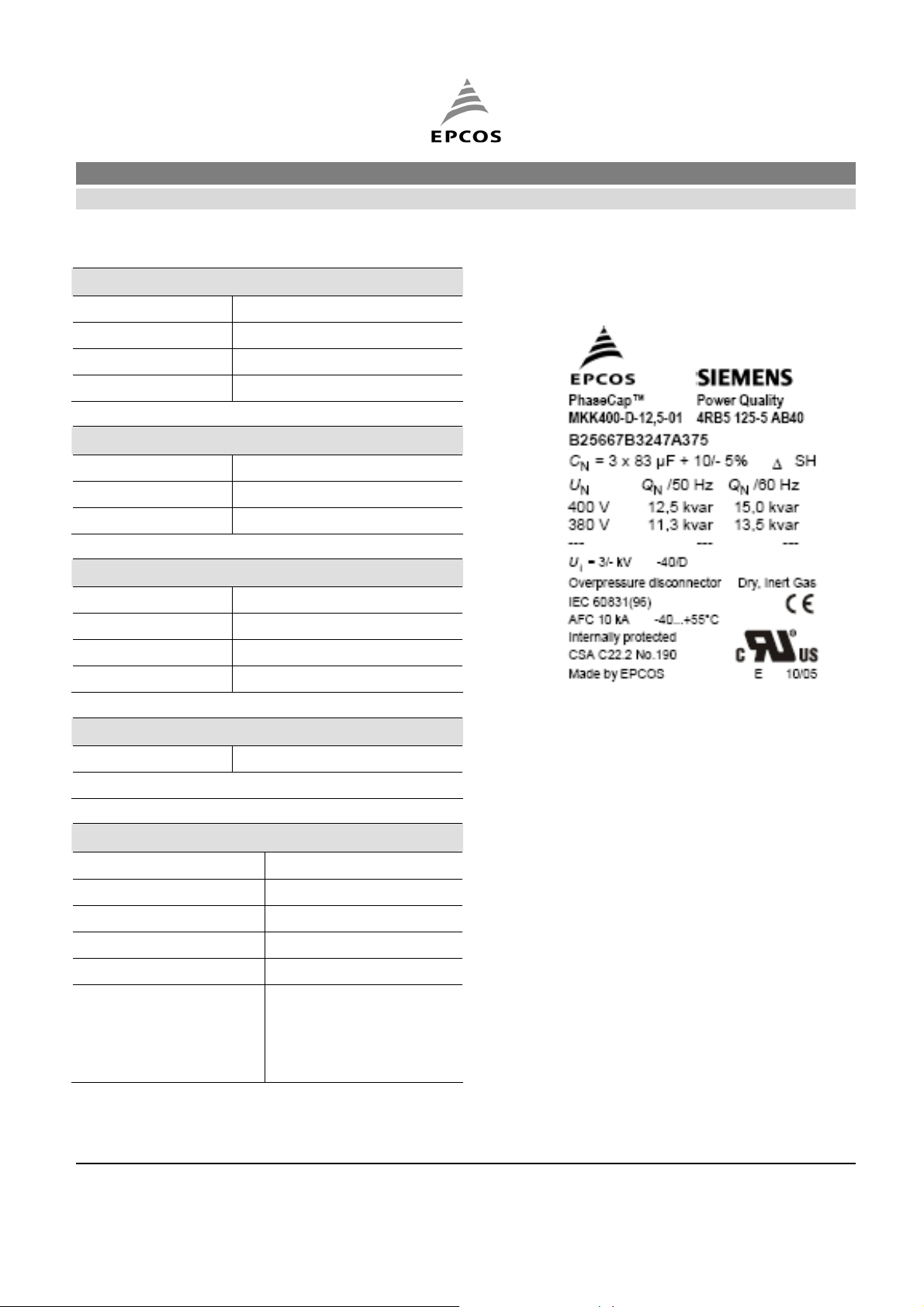
Power Capacitors B25667B3247A375
Power Factor Correction MKK400-D-12.5-01
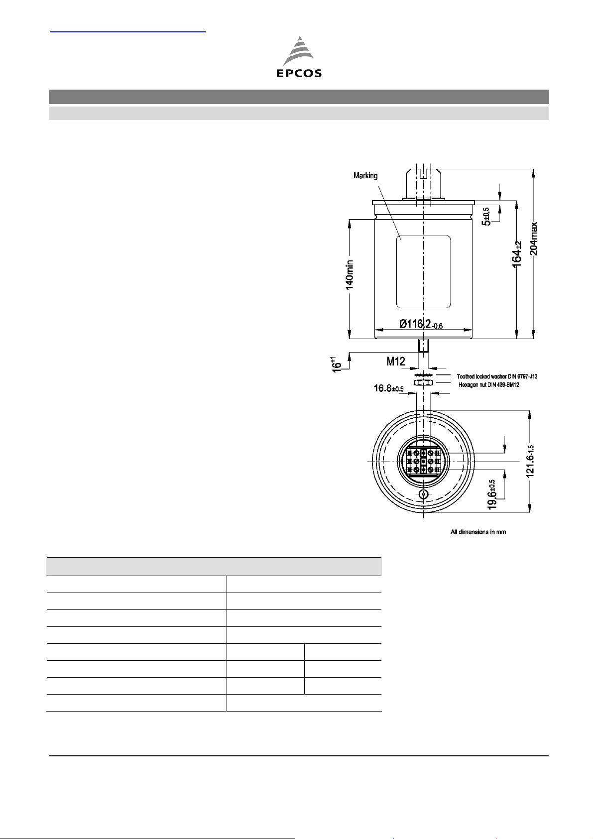
Construction Dimensional drawing
Dielectric: Polypropylene film
Gas-impregnated / dry type
Concentric winding
Wave cut
Extruded round aluminum can with stud
Provided with ceramic discharge module
Triple safety system
Features
Three phase, delta connected
Self-healing technology
Naturally air cooled (or forced air cooling)
Indoor mounting
Typical applications
For Power Factor Correction
Terminals
SIGUT terminals
Mounting parts
Threaded stud at bottom of can
(
max. torque = 10 Nm for M12)
Technical data and specifications
Characteristics
Rated capacitance CR 3 x 83 µF
Tolerance -5 / +10%
Connection D (Delta)
Rated voltage VR 400 VAC
Rated frequency f
Output 12.5 kvar 15 kvar
Rated current IR
tanδ (dielectric) 0.2 W / kvar
50 Hz 60 Hz
R
18 A 22 A
Edition 2.
FK PFC RD / VA 20.10.05
Page 1 of 3
Power Capacitors B25667B3247A375
Power Factor Correction MKK400-D-12.5-01
Maximum ratings
U
(up to 8 h daily) 440 VAC
max
U
(up to 1 min) 520 VAC
max
I
1.3 x IR (A)
max
IS 200 x IR (A)
Test data
UTT 900 VAC / 50 Hz during 10 s
UTC 3,000 VAC / 50 Hz during 10 s
tanδ (50 Hz) ≤ 0.6 W / kvar
Climatic category / -40/D
Label design
T
(-) 40 ºC
min
T
(+) 55 ºC
max
Humidity av. rel. < 95%
Maximum altitude 4,000 m
Mean life expectancy
tLD Up to 115,000 hours
Max. 5000 switchings per year acc. to IEC 60831
Design data
Dimensions (∅ x l)
Weight approx 1.1 kg
Impregnation Dry, inert gas
Fixing Threaded bolt M12
Max. torque (Al can stud) 10 Nm
Mounting position
121 x 164 mm
Any mounting position
possible. See
“Maintenance and
Installation Manual” for
further details.
Edition 2.
FK PFC RD / VA 20.10.05
Page 2 of 3

Power Capacitors B25667B3247A375
Power Factor Correction MKK400-D-12.5-01
Terminals
Degree of protection Isolated terminals, IP20
Max. torque 1.2 Nm
Terminal cross section 16 mm2 (5 AWG)
Maximum terminal current 50 A
Creepage distance 12.7 mm
Clearance 9.6 mm
Safety
Mechanical safety Overpressure disconnector
Max. short circuit current (AFC: 10 kA)
Discharge resistor time ≤ 1 min (75 V)
Reference Standards
IEC 60831-1/2, UL 810-5th edition
Certification: cUL file E238746
U Please read information about PFC capacitors and cautions as well as installation and maintenance instructions (Power Factor Correction Product Profile,
actual version, and Installation and Maintenance Instructions for PFC-capacitors, available in the Internet) to ensure optimum performance and prevent products
from failing, and in worst case, bursting and fire.
Information given in the PFC-product profile and values given in the data sheet reflect typical specifications. You are kindly requested to approve our product
specifications or request our approval for your specification before ordering.
© EPCOS AG 2005. All Rights reserved. Reproduction, publication and dissemination of this data sheet, enclosures hereto and the information contained therein
without EPCOS' prior express consent is prohibited. The information contained in this data sheet describes the type of component and shall not be considered
as guaranteed characteristics. Purchase orders are subject to the General Conditions for the Supply of Products and Services of the Electrical and Electronics
Industry recommended by the ZVEI (German Electrical and Electronic Manufacturers' Association), unless otherwise agreed.
Edition 2.
FK PFC RD / VA 20.10.05
Page 3 of 3

 Loading...