

Page 1

EMC filters
General
Date: January 2006
© EPCOS AG 2006. Reproduction, publication and dissemination of this data sheet and the
information contained therein without EPCOS’ prior express consent is prohibited.
Page 2

General
EMC basics
1 EMC basics
1.1 Legal background
Electromagnetic compatibility (EMC) has become an essential property of electronic equipment. In
view of the importance of this topic, the European legislator issued the EMC Directive as early as
1996 (89/336/EEC): it has since been incorporated at national level by the EU member states in the
form of various EMC laws and regulations.
The EU’s new EMC Directive (2004/108/EC of December 15, 2004) contains several significant innovations compared to the version in force since 1996. It will become binding on all equipment put
on the market after the elapse of the transitional period in July 2009. The most important changes
include:
Regulations for fixed installations
Abolition of the “competent body”
Conformity assessment may also be made without harmonized standards
New definitions of terms (”equipment”, “apparatus”, “ fixed installation”)
New requirements on mandatory information, traceability
Improved market surveillance
The definition of “apparatus“ has now become clearer, so that its scope of validity now covers only
apparatus that the end user can use directly. Basic components such as capacitors, inductors and
filters are definitively excluded.
The “essential requirements” must be observed by all apparatus offered on the market within the
EU. This ensures that all apparatus operate without interferences in its electromagnetic environment without affecting other equipment to an impermissible extent.
1.2 Directives and CE marking
Manufacturers must declare that their apparatus conform to the protection objectives of the EMC
Directive by attaching the CE conformity mark to all apparatus and packaging. This implies that they
assume responsibility vis-à-vis the legislators for observing the relevant emission limits and interference immunity requirements.
The interference immunity requirements in particular are becoming increasingly important for the
operators of apparatus, installations and systems, as their correct functioning can be ensured only
if sufficient EMC measures are taken. However, the need for constant functionality also implies high
availability of installations and systems and thus represents a significant performance figure for the
cost-effective operation of the equipment.
It should be noted that the CE conformity mark not only asserts electromechanical compatibility but
also confirms the observance of all the EU Directives applying to the product concerned. The most
important general directives apart from the EMC Directive include the Low-Voltage Directive and
the Machinery Directive.
Some of these directives also include EMC requirements. Examples are the R&TTE Directive (for
radio and telecommunications terminal equipment) and the Medical Products Directive. The EMC
Directive does not apply to those products which are covered by these directives.
The manufacturer is responsible for taking the necessary steps to ensure that all applicable directives are observed.
Please read Important notes
and Cautions and warnings.
01/06 2
Page 3
General
EMC basics
1.3 EMC standards
Dedicated product standards or product family standards are available for many kinds of equipment
(see Section 1.9). All equipment not covered by these EMC standards are assessed on the basis
of the generic standards. Special rules apply to larger and more complex installations which are assembled on site and are not freely available commercially (see Chapter “Application notes”).
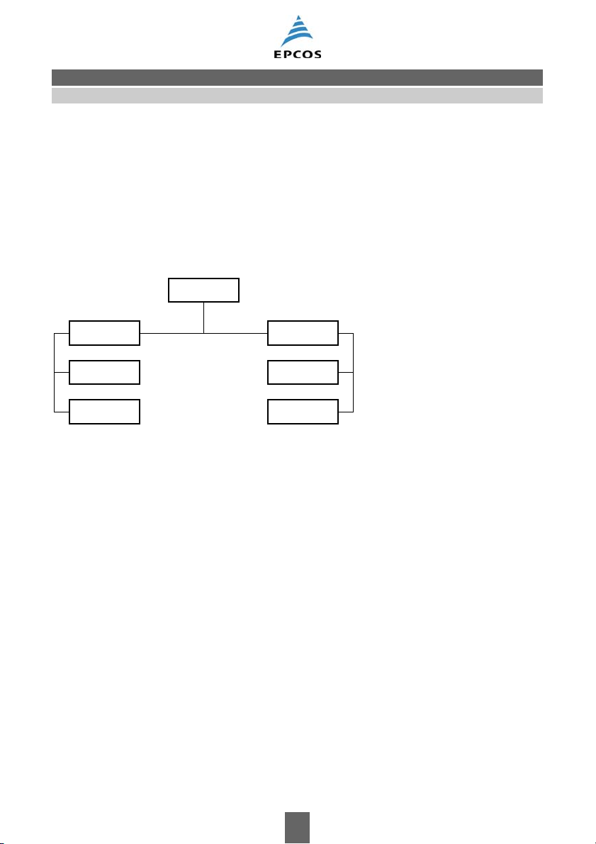
1.4 Basic information on EMC
The term EMC covers both electromagnetic emission and electromagnetic susceptibility
(
Figure 1).
EMC
Emission Susceptibility
EME
EMS
CE
RE
source equipment
conducted
radiated
CS
RS
Disturbed Interference Propagation
SSB0007-3-E
Figure 1 EMC terms
EMC = Electromagnetic compatibility
EME = Electromagnetic emission
EMS = Electromagnetic susceptibility
CE = Conducted emission
CS = Conducted susceptibility
RE = Radiated emission
RS = Radiated susceptibility
An interference source may generate conducted or radiated electromagnetic energy, i.e. conducted
emission (CE) or radiated emission (RE). This also applies to the electromagnetic susceptibility of
disturbed equipment.
In order to work out cost-efficient solutions, all phenomena must be considered, and not just one
aspect such as conducted emission.
Please read Important notes
and Cautions and warnings.
01/06 3
Page 4
General
EMC basics
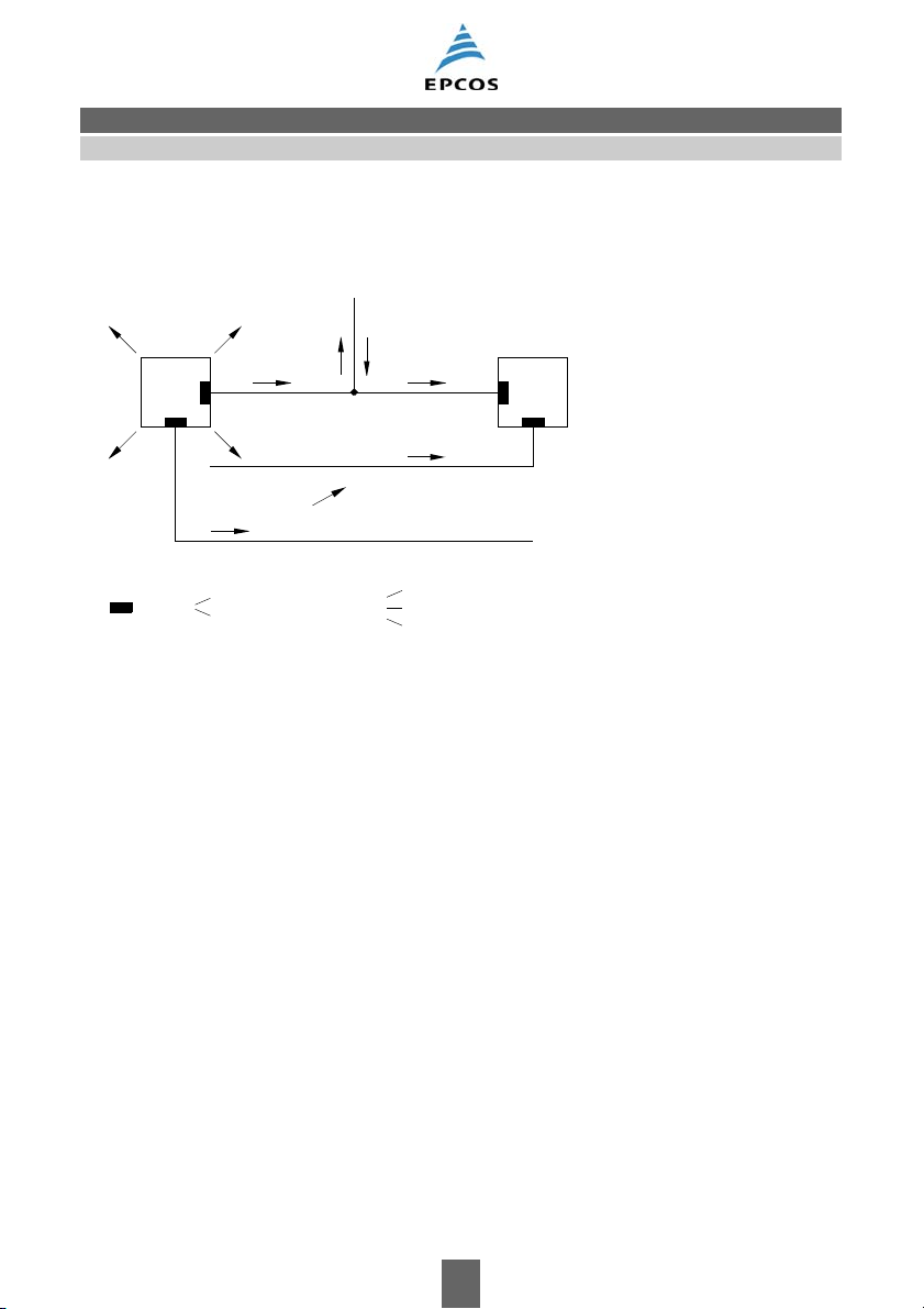
EMC components are used to reduce conducted electromagnetic interferences to the limits defined
in an EMC plan or below the limits specified in the EMC standards (
Figure 2). These components
may be installed either in the source or in the disturbed equipment.
RE
RE
Filter
Source
Interference currents
CE
Interference voltages
RE
RE
CE
CE
CE
Control line
Power supply
CE
RE
RE Magnetic field
CE
CE
Electric field
Electromagnetic field
Disturbed
equip-
ment
Signal line
SSB1685-G-E
Figure 2 Susceptibility model and filtering
EPCOS offers EMC components with a wide range of rated voltages and currents for power lines
as well as for signal and control lines.
Please read Important notes
and Cautions and warnings.
01/06 4
Page 5
General
EMC basics
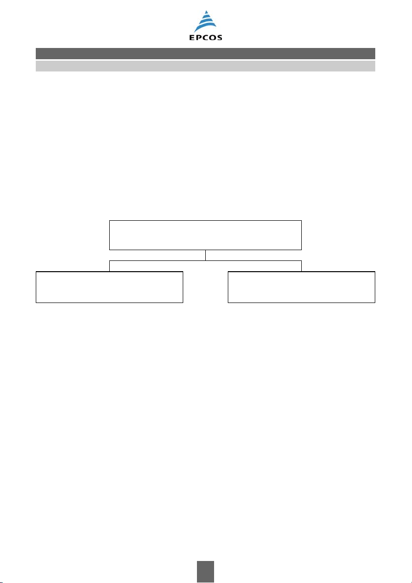
1.5 Interference sources and disturbed equipment
Interference source
An interference source is an electrical equipment which emits electromagnetic interferences. We
can differentiate between two main groups of interference sources corresponding to the type of frequency spectrum emitted (
Interference sources with discrete frequency spectra (e.g. high-frequency generators and microprocessor systems) emit narrowband interferences.
Switchgear and electric motors in household appliances, however, spread their interference energy
over broad frequency bands and are considered to belong to the group of interference sources having a continuous frequency spectrum.
Figure 3).
Interference source (emission)
Discrete frequency spectrum
(Sine-wave, low energy)
μP systems
RF generators
Medical equipment
Data processing systems
Microwave equipment
Ultrasonic equipment
RF welding apparatus
Radio and TV receivers
Switch-mode power supplies
Frequency converters
UPS systems
Electronic ballasts
Figure 3 Interference sources
Please read Important notes
and Cautions and warnings.
Continuous frequency spectrum
(Impulses, high energy)
Switchgear (contactors, relays)
Household appliances
Gas discharge lamps
Power supplies and battery chargers
Frequency converters
Ignition systems
Welding apparatus
Motors with brushes
Atmospheric discharges
01/06 5
Page 6
General
EMC basics
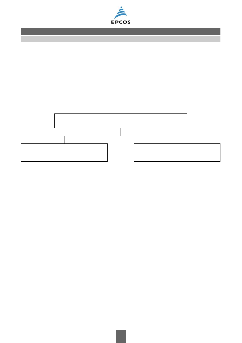
Disturbed equipment
Electrical equipment or systems subject to interferences and which can be adversely affected by it
are termed disturbed equipment.
In the same way as interference sources, disturbed equipment can also be categorized corresponding to frequency characteristics. A distinction can be made between narrowband and broadband
susceptibility (
Narrowband systems include radio and TV sets, for example, whereas data processing systems are
generally characterized as broadband systems.
Figure 4).
Disturbed equipment (susceptibility)
Narrowband susceptibility Broadband susceptibility
Radio and TV receivers
Radio reception equipment
Modems
Data transmission systems
Radio transmission equipment
Remote-control equipment
Cordless and cellular phones
Figure 4 Disturbed equipment
Please read Important notes
and Cautions and warnings.
Digital and analog systems
Data processing systems
Process control computers
Control systems
Sensors
Video transmission systems
Interfaces
01/06 6
Page 7
General
EMC basics
1.6 Propagation of interferences
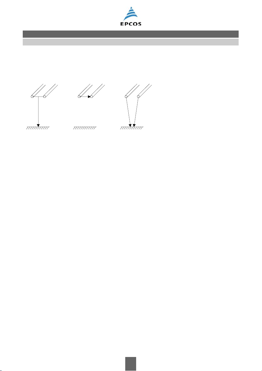
Interference voltages and currents can be grouped into common-mode interferences, differentialmode interferences and unsymmetrical interferences:
(a)
V
as
Common-mode Differential-mode Unsymmetrical
propagation propagation propagation
(b)
(c)
V
s
V
us1 Vus2
SSB1465-P-E
Figure 5 Propagation modes
5 (a)
Common-mode interferences (asymmetrical interferences):
– occurs between all lines in a cable and reference potential;
– occurs mainly at high frequencies (approximately 1 MHz upwards).
5 (b)
Differential-mode interferences (symmetrical interferences):
– occurs between two lines (L-L, L-N);
– occurs mainly at low frequencies (up to several hundred kHz).
5 (c)
Unsymmetrical interferences:
– This term is used to describe interferences between one line and the reference potential.
Please read Important notes
and Cautions and warnings.
01/06 7
Page 8
General
EMC basics
1.7 Characteristics of interferences
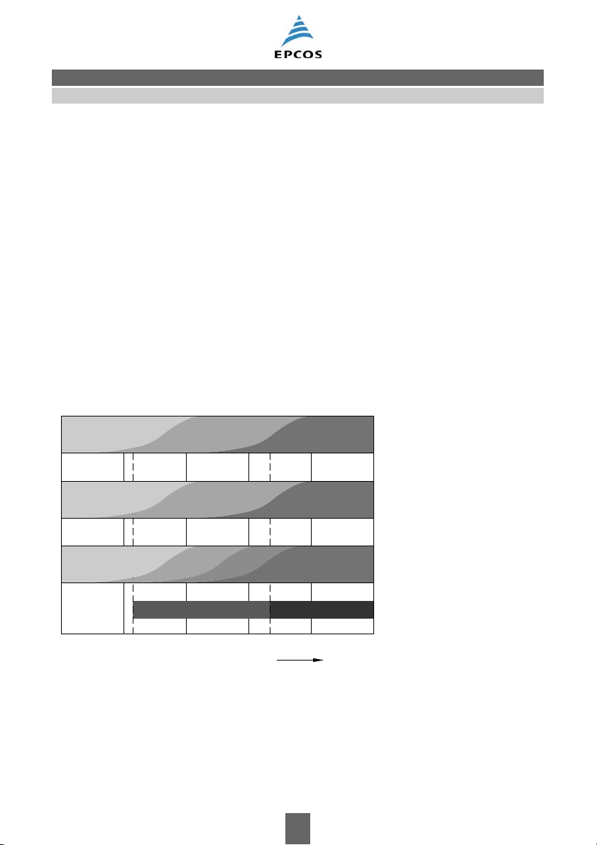
In order to be able to choose the correct EMC measures, we need to know the characteristics of the
interferences, how they are propagated and the coupling mechanisms. In principle, the interferences can also be classified according to their propagation mode (
Figure 6). At low frequencies, it can
be assumed that the interferences only spreads along conductive structures, at high frequencies
virtually only by means of electromagnetic radiation. In the MHz frequency range, the term coupling
is generally used to describe the mechanism.
Analogously, conducted interferences at frequencies of up to several hundred kHz is mainly differential-mode (symmetrical), at higher frequencies, it is common-mode (asymmetrical). This is be-
cause the coupling factor and the effects of parasitic capacitance and inductance between the conductors increase with frequency.
X capacitors and single chokes offer effective differential-mode insertion loss. Common-mode interferences can be reduced by current-compensated chokes and Y capacitors. However, this requires a well-designed EMC-compliant grounding and wiring system.
The categorization of types of interference and suppression measures and their relation to the frequency ranges is reflected in the frequency limits for interference voltage and interference field
strength measurements.
SSB1466-X-E
Differential mode
Common mode
Field
Interference
characteristic
Line
X cap
Pc ch.
Coupling
Y cap
CC ch.
Ground
Interference voltage
10
_
2
10
_
1
10
0
Figure 6 Frequency range overview
Pc ch. = Iron powder core chokes, but also all single chokes
X cap = X capacitors
Cc ch. = Current-compensated chokes
Y cap = Y capacitors
Please read Important notes
and Cautions and warnings.
10
1
Field
Shielding
Field strength
102 MHz 10
f
01/06 8
Interference
propagation
Remedies
Limits
3
Page 9
General
EMC basics
1.8 EMC measurement methods
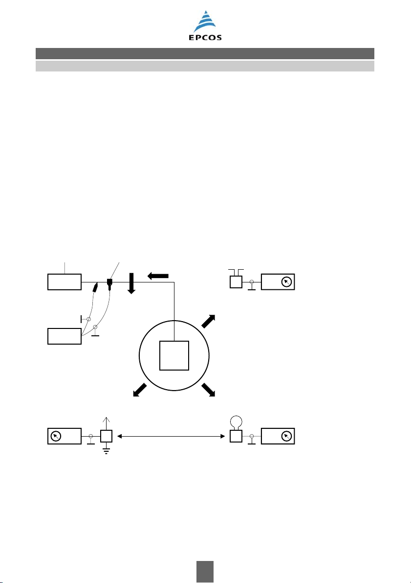
As previously mentioned, an interference source causes both conducted and radiated electromagnetic interferences.
Propagation along lines can be detected by measuring the interference current and the interference
voltage (
Figure 7).
The effect of interference fields on their immediate vicinity is assessed by measuring the magnetic
and electric fields. This kind of propagation is also frequently termed electric or magnetic coupling
(near field).
In higher frequency ranges, characterized by the fact that equipment dimensions are in the order of
magnitude of the wavelength under consideration, the interference energy is mainly radiated directly (far field). Conducted and radiated propagation must also be taken into consideration when testing the susceptibility of disturbed equipment.
Interference sources, such as sine-wave generators as well as pulse generators with a wide variety
of pulse shapes are used for such tests.
Power supply
Line impedance
stabilization
network
Measuring receiver
Spectrum analyzer
Storage oscilloscope
Transient recorder
Current probe
Voltage
probe
Rod antenna
Ι
int
V
int
Broadband dipole antenna
Measuring receiver
P
int
Source
E
int
H
int
Loop antenna
Near field coupling
Measuring receiver
Measuring receiver
SSB0016-2-E
Figure 7 Propagation of electromagnetic interferences and EMC measurement methods
= Magnetic interference fields
H
int
E
= Electrical interference fields
int
= Electromagnetic interference fields (radiated emission)
P
int
I
= Interference current
int
V
= Interference voltage
int
Please read Important notes
and Cautions and warnings.
01/06 9
Page 10
General
EMC basics
1.9 EMC standards
New, harmonized European standards have been issued in conjunction with the EU’s EMC Directive or national EMC legislation. These specify measurement methods and limits or test levels for
both the emissions and immunity of electrical equipment, installations and systems.
The subdivision of the European standards into various categories (see following table) makes it
easier to find the rules that apply to the respective equipment. The generic standards always apply
to all equipment for which there is no specific product family standard or dedicated product stan-
dard. The basic standards contain information on interference phenomena and general measuring
methods.
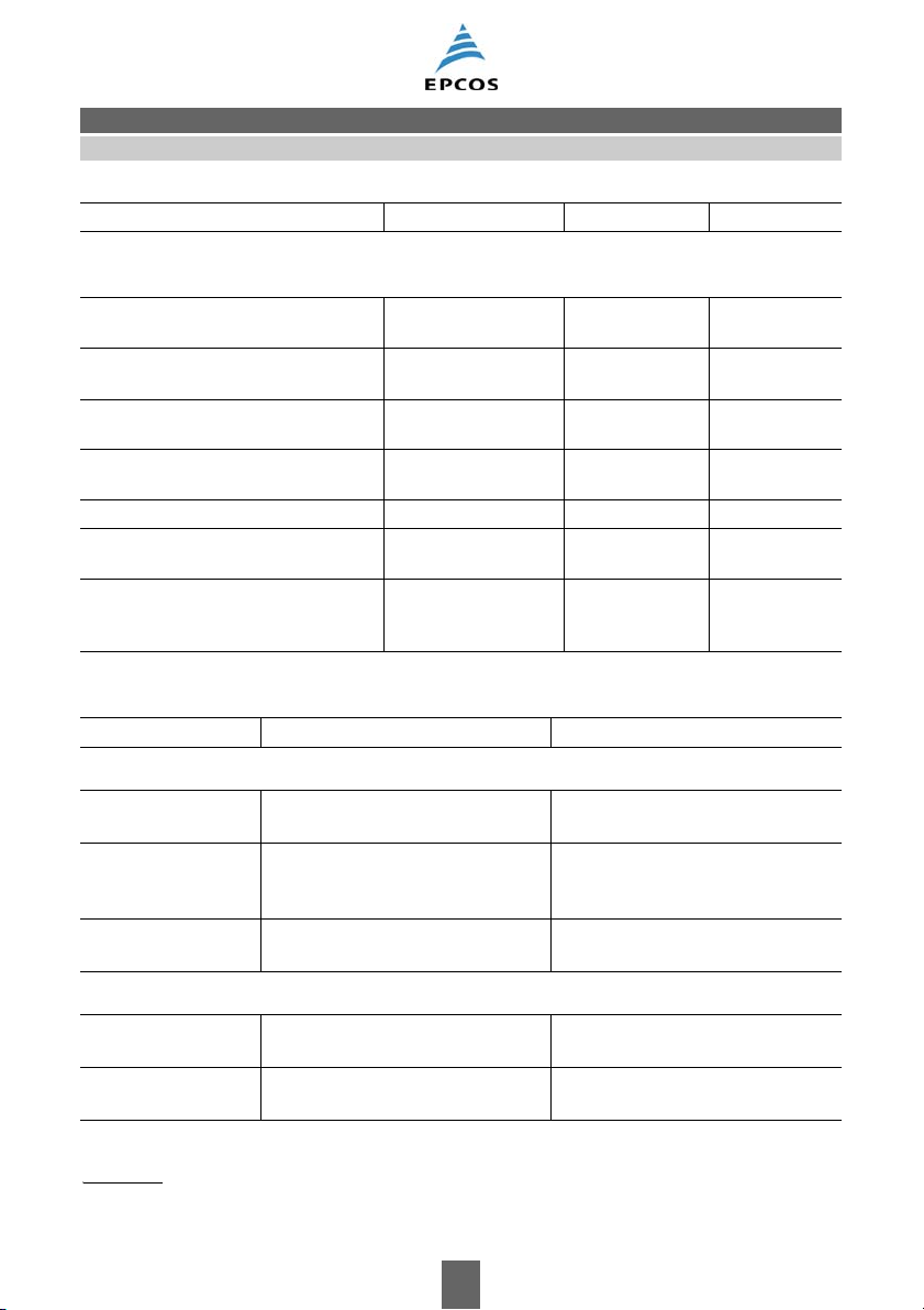
The following standards and regulations form the framework of the conformity tests:
EMC standards Germany Europe International
Generic standards
define the EMC environment in which a device is to operate according to its intended use.
Emissionresidential
industrial
Immunityresidential
industrial
DIN EN 61000-6-3
DIN EN 61000-6-4
DIN EN 61000-6-1
DIN EN 61000-6-2
EN 61000-6-3
EN 61000-6-4
EN 61000-6-1
EN 61000-6-2
IEC 61000-6-3
IEC 61000-6-4
IEC 61000-6-1
IEC 61000-6-2
Basic standards
describe physical phenomena and measurement methods.
Measuring equipment DIN EN 55016-1-x EN 55016-1-x CISPR 16-1-x
Measuring methodsemission
immunity
Harmonics
Flicker
DIN EN 55016-2-x
DIN EN 61000-4-1
DIN EN 61000-3-2
DIN EN 61000-3-3
EN 55016-2-x
EN 61000-4-1
EN 61000-3-2
EN 61000-3-3
CISPR 16-2-x
IEC 61000-4-1
IEC 61000-3-2
IEC 61000-3-3
Immunity parameters
e.g. ESD
EM fields
Burst
Surge
Induced RF fields
Magnetic fields
Voltage dips
DIN EN 61000-4-2
DIN EN 61000-4-3
DIN EN 61000-4-4
DIN EN 61000-4-5
DIN EN 61000-4-6
DIN EN 61000-4-8
DIN EN 61000-4-11
EN 61000-4-2
EN 61000-4-3
EN 61000-4-4
EN 61000-4-5
EN 61000-4-6
EN 61000-4-8
EN 61000-4-11
IEC 61000-4-2
IEC 61000-4-3
IEC 61000-4-4
IEC 61000-4-5
IEC 61000-4-6
IEC 61000-4-8
IEC 61000-4-11
Please read Important notes
and Cautions and warnings.
01/06 10
Page 11
General
EMC basics
EMC standards Germany Europe International
Product family standards
define limit values for emission and immunity.
ISM equipment emission
immunity
Household appliances emission
immunity
Lighting emission
immunity
Radio and TV emission
equipment immunity
DIN EN 55011
1)
DIN EN 55014-1
DIN EN 55014-2
DIN EN 55015
DIN EN 61547
DIN EN 55013
DIN EN 55020
EN 55011
1)
EN 55014-1
EN 55014-2
EN 55015
EN 61547
EN 55013
EN 55020
CISPR 11
1)
CISPR 14-1
CISPR 14-2
CISPR 15
IEC 1547
CISPR 13
CISPR 20
High-voltage systems emission DIN VDE 0873 — CISPR 18
ITE equipment
3)
Vehicles emission
emission
immunity
immunity
DIN EN 55022
DIN EN 55024
DIN EN 55025
—
EN 55022
EN 55024
EN 55025
2)
CISPR 22
CISPR 24
2)
CISPR 25
ISO 11451
ISO 11452
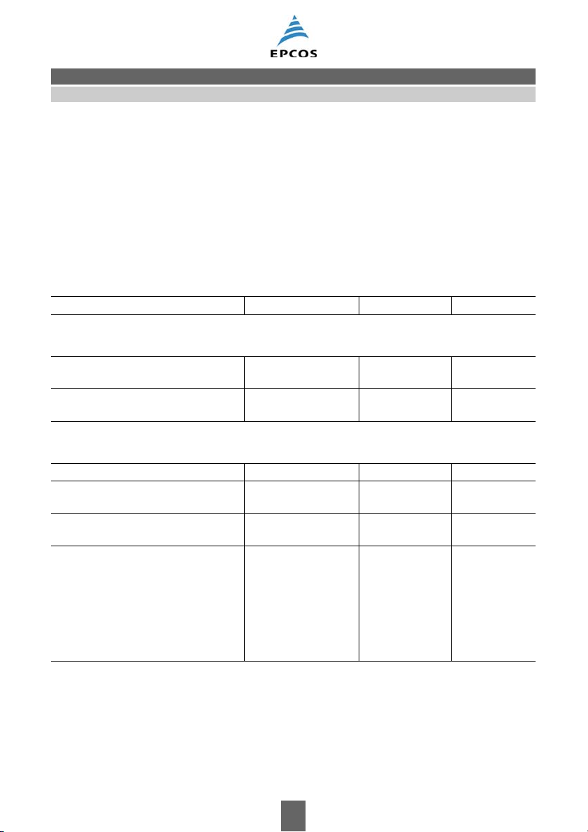
The following table shows the most important standards concerning immunity.
Standard Test characteristics Phenomena
Conducted interferences
EN 61000-4-4
IEC 61000-4-4
EN 61000-4-5
IEC 61000-4-5
5/50 ns (single impulse)
2.5 kHz, 5 kHz or 100 kHz burst
1.2/50 μs (open-circuit voltage)
8/20 μs (short-circuit current)
Burst
Cause: switching processes
Surge (high-energy transients)
Cause: lightning strikes mains supply,
switching processes
EN 61000-4-6
IEC 61000-4-6
1; 3; 10 V
150 kHz to 80 MHz (230 MHz)
High-frequency coupling
Narrow-band interferences
Radiated interferences
EN 61000-4-3
IEC 61000-4-3
EN 61000-4-8
IEC 61000-4-8
1) Is governed by the safety and quality standards of the product families.
2) The EU Automotive Directive (95/54/EC) also covers limits and immunity requirements.
3) Some equipment is covered by the R & TTE Directive (Radio- and Telecommunications Terminals).
Please read Important notes
and Cautions and warnings.
3; 10 V/m
80 to 1000 MHz
up to 100 A/m
50 Hz
High-frequency interference fields
Magnetic interference fields
with power-engineering frequency
01/06 11
Page 12
General
EMC basics
Standard Test characteristics Phenomena
Electrostatic discharge (ESD)
EN 61000-4-2
to 15 kV Electrostatic discharge
IEC 61000-4-2
Instability of the supply voltage
EN 61000-4-11
IEC 61000-4-11
EN 61000-4-11
IEC 61000-4-11
e.g. 40 % V
0 % V
e.g. 40 % V
(2 s reduction, 1 s reduced voltage,
for 1 … 50 periods
N
for 0,5 periods
N
or 0 % V
N
N
Voltage dips
Short-term interruptions
Voltage variations
2 s increase)
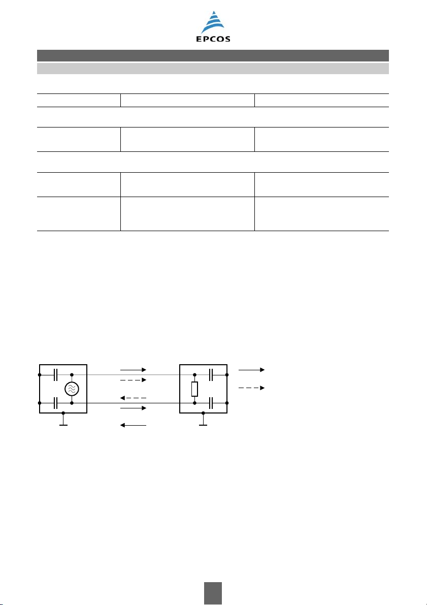
1.10 Propagation of conducted interferences
In order to be able to select suitable EMC components, the way in which conducted interferences
are propagated needs to be known.
A floating interference source primarily emits differential-mode interferences which are propagated
along the connected lines. The interference current will flow towards the disturbed equipment on
one line and away from it on the other line, just as the mains current does.
Differential-mode interferences occur mainly at low frequencies (up to several hundred kHz).
Interference Disturbed
source equipment
Common-mode
interference current
C
p
C
R
p
Differential-mode
interference current
C
: Parasitic capacitance
p
SSB0022B-E
Figure 8 Common-mode and differential-mode interferences
However, parasitic capacitances in interference sources and disturbed equipment or intended
ground connections, also lead to an interference current in the ground circuit. This common-mode
interference current flows towards the disturbed equipment through both the connecting lines and
returns to the interference source through ground. Since the parasitic capacitances will tend towards representing a short-circuit with increasing frequencies and the coupling effects the connecting cables and the equipment itself will increase correspondingly, common-mode interferences become dominant above some MHz.
Please read Important notes
and Cautions and warnings.
01/06 12
Page 13
General
EMC basics
In Europe, the term of an “unsymmetrical interference” is used to describe the interference voltage
between one line and a reference potential. It consists of symmetrical and asymmetrical parts.
EPCOS specifies characteristic values of insertion loss for the individual filter types in order to facilitate the selection of suitable EMC filters.
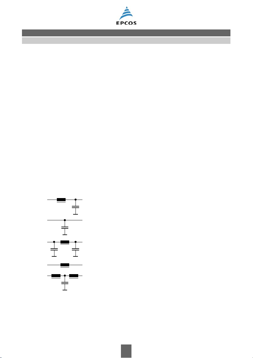
1.11 Filter circuits and line impedance
EMC filters are virtually always designed as reflecting lowpass filters, i.e. they reach their highest
insertion loss when they are – on the one hand – mismatched to the impedance of the interference
source and disturbed equipment and – on the other hand – mismatched to the impedance of the
line. Possible filter circuits for various impedance conditions are shown in
Figure 9.
It is, therefore, necessary to find out the impedances so that optimum filter circuit designs as well
as economical solutions can be implemented.
The impedances of the power networks under consideration are usually known from calculations
and extensive measurements, whereas the impedances of interference sources or disturbed equipment are, in most cases, not or only inadequately known.
For this reason, it is impossible to design the most suitable filter solution without EMC tests. In this
context, we offer our customers the competent consulting of our skilled staff, both on-site and in our
EMC laboratory in Regensburg (see also “EMC services”, Section 7, “EMC laboratory”).
Line Impedance of
impedance source of interference/disturbed equipment
low high
high high
high high
unknown
low low
low low
unknown
unknown
unknown
Figure 9 Filter circuits and impedance relationships
Please read Important notes
and Cautions and warnings.
SSB0042-Q-E
01/06 13
Page 14

General
Selection criteria
2 Selection criteria for EMC filters
To comply with currently valid regulations, a frequency range of 150 kHz to 1000 MHz has to be
taken into consideration, in most cases, in order to ensure electromagnetic compatibility; in addition,
however, further aspects such as low-frequency phenomena should be considered.
EMC filters must thus have good RF characteristics and are ususally required to be effective over
a broad frequency range.
For individual components (inductors, capacitors) the RF characteristics are specified by stating
the impedance as a function of frequency.
The insertion loss is used as a criterion for selecting EMC filters (see Section 3.1.17).
If the device under test (DUT) is terminated on both sides with an ohmic impedance of 50 Ω, for
example, the result of the measurement is referred to as being the 50-Ω insertion loss.
Depending on the particular application intended, priorities for consideration of the three possible
kinds of insertion loss
common-mode (asymmetrical)
differential-mode (symmetrical) or
unsymmetrical
must be decided upon.
The measuring method for 50-Ω insertion loss has been adapted from the field of communications
engineering and is also specified in the relevant national and international standards.
Although it permits a comparison of different filters, it provides only little information on the efficiency
in practical applications.
The reason is – as already mentioned in the previous section – that neither the interference source
or disturbed equipment nor the connected power line system will have an ohmic impedance of 50 Ω
at frequencies below 1 MHz.
Likewise, the attenuation of interference pulses cannot simply be determined on the basis of the
insertion loss curve. In this case, it is also necessary to take the non-linear response of the EMC
chokes in the filters into consideration.
We can quote filter-specific values on request if you send us the pulse shapes in question.
Please read Important notes
and Cautions and warnings.
01/06 14
Page 15
General
Terms and definitions
3 Terms and definitions
3.1 Electrical characteristics
3.1.1 Rated voltage V
R
The rated voltage VR is either the maximum RMS operating voltage at the rated frequency or the
highest DC operating voltage which may be continuously applied to the filter at temperatures between the lower category temperature T
and the upper category temperature T
min
. Filters which
max
are rated for a frequency of 50/60 Hz may also be operated at DC voltages.
3.1.2 Nominal voltage V
N
The nominal voltage VN is the voltage which designates a network or electrical equipment and to
which specific operating characteristics are referred.
IEC 60038 defines the most widely used nominal voltages for public supply networks (e.g.
230/400 V, 277/480 V, 400/690 V). It is recommended that the voltage at the transfer points should
not deviate from the nominal voltage by more than ±10% under normal network conditions.
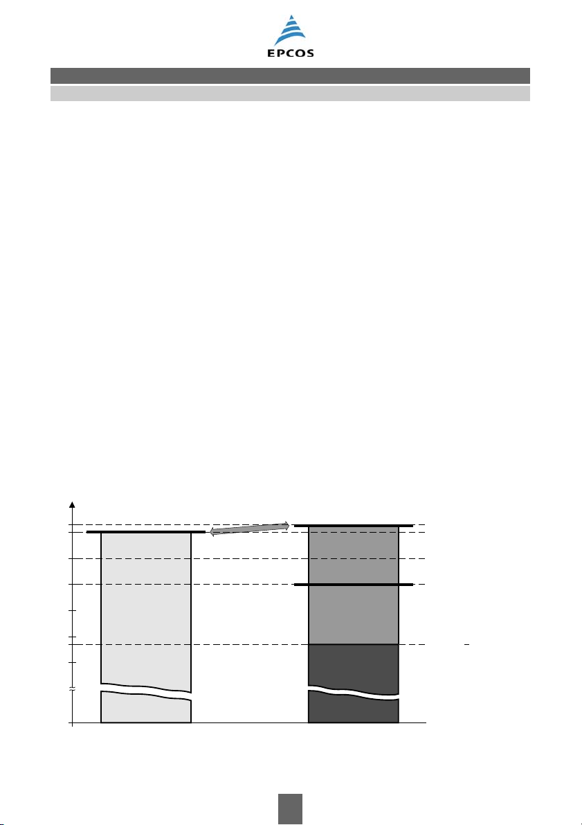
3.1.3 Difference between rated and nominal voltage
For filters, the rated voltage is defined as a reference parameter. It specifies the maximum voltage
at which the filter can be continuously operated (see Section 3.1.1). This voltage must never be exceeded, as otherwise damage may occur.
Only small deviations are tolerated, such as may occur when a filter with a rated voltage of 250 V
is operated at in a network with a nominal voltage of 230 V (230 V +10% = 253 V). This relationship
is shown in
V
250
V
240
230
220
Figure 10.
Filter Network
Rated voltage Nominal voltage V
R N
V
253 (VN +10 %)
V
N
210
200
0
Figure 10 Difference between rated and nominal voltage
Please read Important notes
and Cautions and warnings.
01/06 15
SSB1592-S-E
207 (V
N
10 %)
Page 16
General
Terms and definitions
When EMC filters and other EMC components are selected, care shall be taken to ensure that the
maximum line voltage in each case, e.g. V
mitted according to EN 133200.
+10%, is not exceeded. Short voltage surges are per-
N
3.1.4 Network types
The filters are approved for various network types (e.g. TN, TT, IT networks). They are described
in Section 7 “Power distribution systems”.
3.1.5 Test voltage V
The test voltage V
test
is the AC or DC voltage which may be applied to the filter for the specified test
test
duration at the final inspection (100% test). If necessary, we recommend a single repetition of the
test at a maximum of 80% of the specified voltage. The rate of voltage rise or fall must then not exceed 500 V/s. The time shall be measured as soon as 90% of the test voltage permissible for the
repeat test has been reached. During the test, no dielectric breakdown may occur (the insulation
would no longer limit the current flow). Healing effects of the capacitors are permissible.
3.1.6 Rated current I
R
The rated current IR is the maximum AC or DC current at which the filter can be continuously operated under nominal conditions.
Above the rated temperature T
the derating curves (see Section 10).
, the operating current shall as a rule be reduced in accordance with
R
For 2 and 3-line filters, the rated current is specified for the simultaneous flow of a current of this
value though all the lines. For 4-line filters (e.g. filters with three phase lines and one neutral line),
the sum current of the neutral line is assumed to be close to zero.
Higher thermal loads may occur during AC operation due to non-sinusoidal waveforms. These must
be taken into account where necessary.
The temperature rise of the EMC filters at rated current and temperature is tested with a connection
via test cross-sections as specified in UL 508:Aug 22, 2000 "Industrial Control Equipment", Table
43.2, Table 43.3 (broadly similar to EN 60947:1999).
3.1.7 Overload capability
The rated current may be exceeded for a short time. Details of permissible currents and load durations are specified in the various data sheets.
3.1.8 Pulse handling capability
Saturation effects (e.g in the ferrite cores used) may occur when high-energy pulses are applied to
the components and these may lead to impaired interference suppression. The maximum permissible voltage-time integral area is used to characterize the pulse handling capability of chokes and
filters. For standard components a range from 1 to 10 mVs can be assumed. More specific data can
be obtained upon request.
Please read Important notes
and Cautions and warnings.
01/06 16
Page 17
General
Terms and definitions
3.1.9 Current derating I/I
R
At ambient temperatures above the rated temperature stated in the data sheet, the operating current of chokes and filters must be reduced according to the derating curve (see Section 10).
3.1.10 Rated inductance L
R
The rated inductance LR is the inductance which has been used to designate the choke, as
measured at the frequency f
3.1.11 Stray inductance L
The stray inductance L
.
L
stray
(also termed leakage inductance) is the inductance measured through
stray
both coils when a current-compensated choke is short-circuited at one end. This affects differentialmode interferences.
L
stray
SSB1593-L-E
Figure 11 Stray inductance
3.1.12 Inductance decrease ΔL/L
0
The inductance decrease ΔL/L0 is the drop in inductance at a given current relative to the initial
inductance L
measured at zero current. The data sheets specify this as a percentage. This de-
0
crease is caused by the magnetization of the core material, which is a function of the field strength,
as induced by the operating current. Generally the decrease is less than 10%.
, R
3.1.13 DC resistance R
typ
min
, R
max
The DC resistance is the resistance of a line as measured using direct current at a temperature of
20 °C, whereby the measuring current must be kept well below the rated current.
typical value
R
typ
R
minimum value
min
maximum value
R
max
3.1.14 Winding capacitance, parasitic capacitance C
p
Parasitic capacitances Cp, which impair the RF characteristics of the filters, are related to the filter
geometry. These capacitances may affect the lines mutually (differential-mode) as well as the lineto-ground circuit (common-mode). The design of all EMC filters supplied by EPCOS minimizes the
parasitic effects. Due to this, our filters have excellent interference suppression characteristics right
up to high frequencies.
Please read Important notes
and Cautions and warnings.
01/06 17
Page 18
General
Terms and definitions
3.1.15 Quality factor Q
The quality factor Q is the quotient of the imaginary part of the impedance divided by the real part,
measured at frequency f
3.1.16 Measuring frequencies f
.
Q
, f
Q
L
fQ is the frequency for which the quality factor Q of a choke is specified.
is the frequency at which the inductance of a choke is measured.
f
L
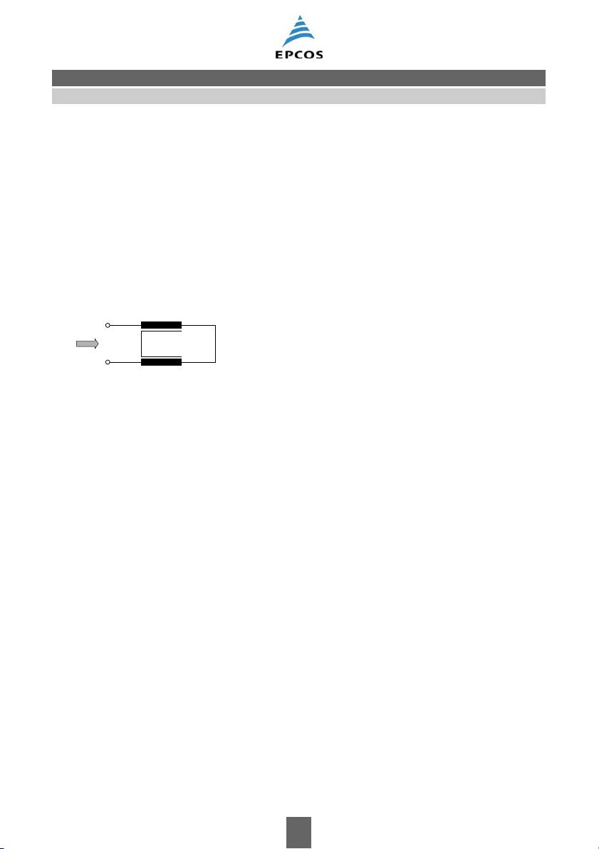
3.1.17 Insertion loss
The insertion loss is a measure for the efficiency of EMC components, as measured by using a standardized test setup (
Z
V
~
0
Figure 12).
Reference measurement
V
10
Z 1
V=V=V
20 10
V
Z
20
.
0
2Z =2
V
0
V
|
|
Z = 50
Ω α
Z
V
~
0
V
DUT
1
A
11 A21
A =
A
12 A22
Z
= 20 log
V
2
V2 = V
V
|
.
A11(ω) =V
1
20
|
2
Insertion loss measurement
= 20 log
.
α
0
SSB1464-G-E
V
|
|
0
V
2
|
2
ω
()
1
|
Figure 12 Definition of insertion loss
The input terminals of the device (circuit) are connected to an RF generator with impedance Z (usually 50 Ω) . At the output of the component, the voltage is measured using an RF voltmeter having
the same impedance Z. The insertion loss is then calculated from the quotient of half the open-circuit generator voltage V
and the filter output voltage V
0
2.
Please read Important notes
and Cautions and warnings.
01/06 18
Page 19
General
Terms and definitions
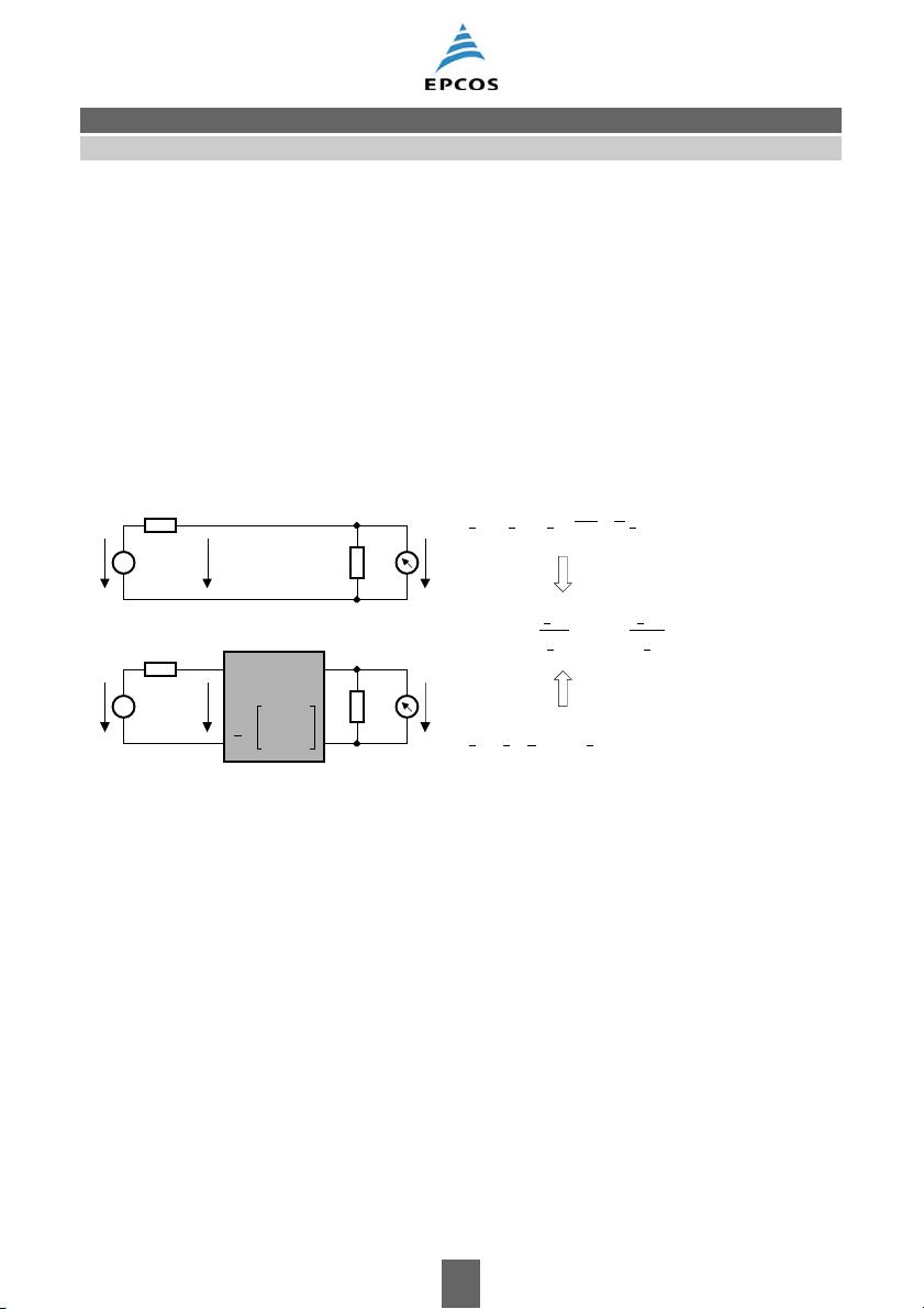
Test setups for insertion loss measurement used for EMC filters
a) Differential mode (symmetrical insertion loss measurement)
Transmitter Filter Receiver
50 Ω
1:1
~
~
V
~
0
1:1
V
2
50 Ω
Figure 13 Symmetrical insertion
loss measurement
to CISPR 17 (1981) Fig. B5
Insertion loss α = 20 lg
V
------------2 ⋅ V
0
[dB]
-
2
SSB0183-Y-E
b) Common mode (asymmetrical measurement, branches connected in parallel)
Transmitter Filter Receiver
50 Ω
~
~
V
~
0
V
50 Ω
2
Figure 14 Asymmetrical measurement
to CISPR 17 (1981) Fig. B6
SSB0184-7-E
Common-mode measurement with lines connected in parallel is widely used in the United States.
Some diagrams in this data book show the results of this measurement in addition to those obtained according to a) and c).
Please read Important notes
and Cautions and warnings.
01/06 19
Page 20

General
Terms and definitions
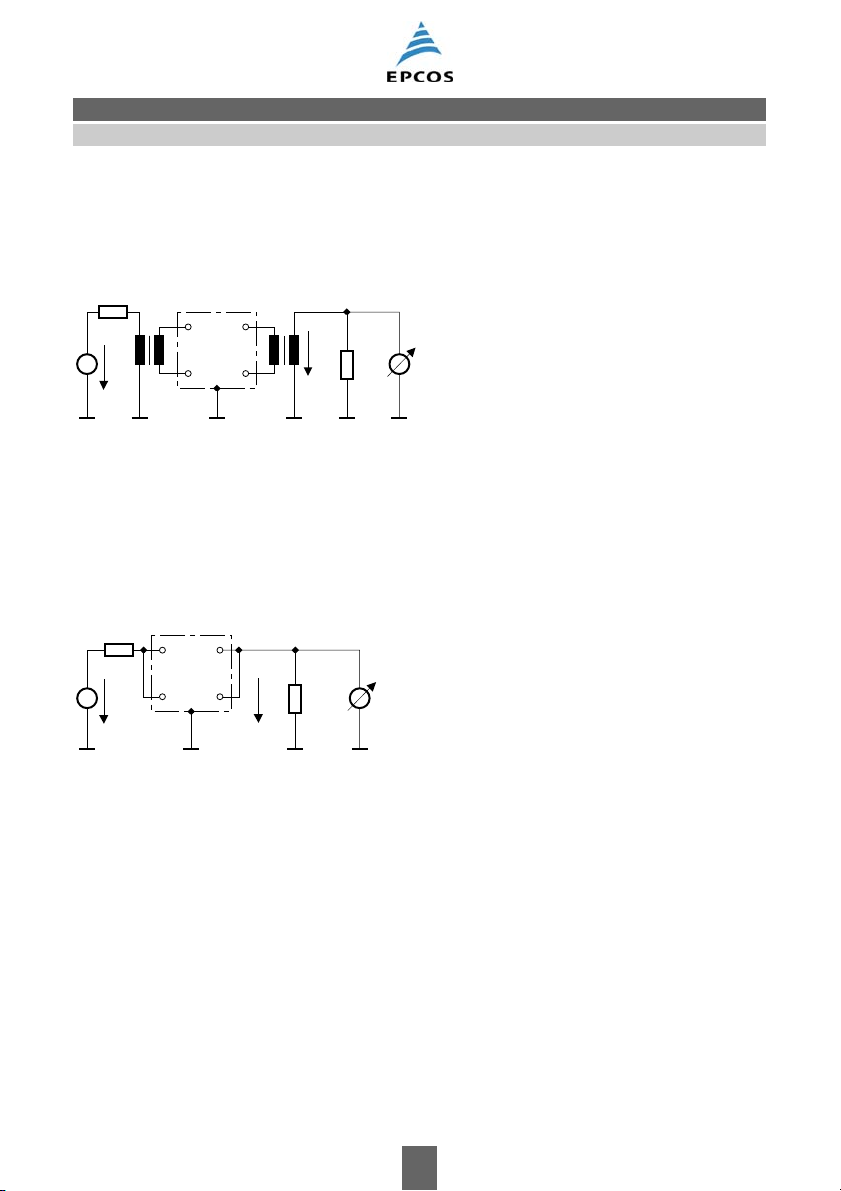
c) Unsymmetrical measurement, adjacent branch terminated
Transmitter Filter Receiver
50 Ω
~
~
V
~
0
Ω 50 50 Ω
V
50 Ω
2
Figure 15 Unsymmetrical measurement
to CISPR 17 (1981) Fig. B7
SSB0185-F-E
The termination of the adjacent line with a defined resistance value has not yet been standardized.
As far as this data book contains insertion loss characteristics determined by other measuring
arrangements, the deviations are indicated where the relevant diagrams are shown.
3.1.18 Leakage current
A detailed description of the leakage current together with measurement circuits and safety hints
may be found in Section 8, “Leakage current”.
3.1.19 Discharge resistor
Discharge resistors are meant to ensure that the energy stored in the capacitors is reduced to low
levels within a short period, so that the voltage at the equipment terminals drops to below permissible maximum values (see also Section 6, “Safety regulations”).
Please read Important notes
and Cautions and warnings.
01/06 20
Page 21

General
Terms and definitions
3.2 Mechanical properties
3.2.1 Potting (economy potting, complete potting)
We distinguish between economy potting and complete potting.
Economy potting is used to fix the various parts of the filter in the case. This is an economical tech-
nique which allows a single resin-casting procedure to be used. Many EMC filters from EPCOS are
thus produced by this method.
Complete potting is required only if the heat dissipation of economy potting is inadequate or in the
case of special customer requirements.
3.2.2 Types of winding
EMC filters from EPCOS use chokes with outstanding technical properties. All chokes have exactly
reproducible and optimized RF characteristics and are matched to the relevant application (e.g.
saturation characteristic with respect to pulses). Both for this reason and because of their design,
the filters have reproducible properties (such as insertion loss).
Chokes with different types of winding are used depending on the respective technical requirements. The different types of winding lead to different choke characteristics, especially at high frequencies.
Single-layer winding:
In comparison to all other types of winding, this type of winding leads to the lowest possible capacitances and thus the highest resonance frequencies.
Multi-layer winding:
In comparison to all other types of winding, this type leads to the highest capacitances and thus the
lowest resonance frequencies.
Random winding:
This method of winding a coil does not permit the final position of a turn to be predetermined exactly.
The cross-section of this type of winding clearly shows a disorderly, “random” arrangement of the
turns. This leads to the parasitic capacitances being only minimally greater than those achieved by
single-layer winding, and the resonance frequencies are comparable to those achieved by singlelayer winding.
RF characteristics of various types of winding
Figure 16 shows impedance as a function of frequency for two chokes of equal inductance. One of
the chokes has a 2-layer winding and the other is randomly wound. The choke with random
windings has a considerably higher first resonance frequency. The secondary resonances are very
much higher than 10 MHz. The impedance at frequencies above the first resonance frequency is
approximately five times higher. This leads to better interference suppression at high frequencies.
Please read Important notes
and Cautions and warnings.
01/06 21
Page 22

General
Terms and definitions
10
6
SSB0948-Q-E
Ω
|Z|
5
2-layer winding
10
Random winding
4
10
3
10
2
10
0
10 10
1
10
2
10
3
kHz 10
4
f
Figure 16 Impedance |Z| versus frequency f
comparison between 2-layer winding and random winding
The RF characteristics of all chokes supplied by EPCOS are reproducible, as the winding processes
which we have developed for single-layer, multi-layer and random winding ensure that the characteristics of the inductors produced display very little variation.
The reproducibility of electrical characteristics of chokes is mainly determined by the production
technique used. At EPCOS, coils are wound mainly by automatic machines (either fully or semiautomated). This permits even complicated winding patterns to be produced in large production
runs with very little variation in product characteristics.
Please read Important notes
and Cautions and warnings.
01/06 22
Page 23

General
Terms and definitions
3.2.3 Recommended tightening torques for screw connections
Screw mounting
Most EPCOS EMC filters have metallic housings. The screw mounting is used for mechanical fixing
and at the same time sets up the large-area connection to the reference ground via the housing contact (see also Section "Mounting instructions“). A distinction must be made between the functions
of mechanical mounting, ground connection and PE connection for protection against shock.
For standard screw connections for the filter mounting, we refer to the state of the art, as the tightening torques depend on the rated size, length, strength category, corrosion protection and lubricant. In case of frontal self-clinching nuts, especially for EMC-compliant mounting, it should be noted that additional fixing is required for filter weights exceeding 10 kg. The installer must always
check the strength of the connection with respect to stresses (such as vibrations and shock).
Unless otherwise specified in the data sheets, we recommend the tightening torques listened in the
following tables.
Recommended tightening torques for self-clinching nuts:
Rated dimension of self-clinching nut Torque in Nm
(tolerance specifications for setting values)
M 4 1.5 ( 1.43 … 1.58)
M 5 3.0 ( 2.85 … 3.15)
M 6 5.1 ( 4.90 … 5.40)
M 8 12.6 (12.00 … 13.20)
Screw connections via threaded bolts
Tightening torques for feedthrough components are specified separately in the introduction to the
Chapter on "1-line filters – feedthrough components".
For current-carrying and PE terminals contacted via threaded bolts, we recommend the following
tightening torques:
Rated dimension of threaded bolts Torque in Nm
(tolerance specifications for setting values)
M 4 1.2 ( 1.10 … 1.30)
M 5 2.0 ( 1.90 … 2.10)
M 6 3.0 ( 2.85 … 3.15)
M 8 6.0 ( 5.70 … 6.30)
M10 10.0 ( 9.00 … 11.00)
M12 15.5 (14.00 … 17.00)
Please read Important notes
and Cautions and warnings.
01/06 23
Page 24

General
Terms and definitions
Screw connections of busbars
For EMC filters with rated currents >100 A, copper bars may be used as contact elements. We recommend the following materials for busbar screw connections.
Part Recommendation
Busbar Copper
Screw Strength category 8.8 or higher to ISO 898 T1,
corrosion protection tZn (hot-dip galvanized)
Nut Strength category 8 or higher to ISO 898 T2,
corrosion protection tZn (hot-dip galvanized)
Spring element on the screw and nut side Conical spring washer to DIN 6796 T2, corrosion
protected
Lubricant MoS
-based
2
In order to ensure the required surface pressure, we recommend the following tightening
torques:
Rated dimension of threaded bolts Torque in Nm
M8 15
M10 30
M12 60
Please read Important notes
and Cautions and warnings.
01/06 24
Page 25

General
Terms and definitions
3.3 Climatic characteristics
3.3.1 Upper and lower category temperature T
The upper category temperature T
and the lower category temperature T
max
max
und T
min
are defined as the
min
highest and the lowest permissible ambient temperature, respectively, at which the filter can be operated continuously.
3.3.2 Rated temperature T
R
The rated temperature TR is defined as the highest ambient temperature at which the filter may be
operated at rated current.
3.3.3 Reference temperature for measurements
According to IEC 60068-1, Section 5.1, a temperature of 20 °C is specified as the reference temperature for all electrical measurements, unless the data sheets specifically define other values.
3.3.4 Climatic category
The usability of components in various climates is defined by the climatic category according to
IEC 60068-1, Annex A. It is made up of three parameters delimited by slashes.
These parameters represent the stress temperatures for the tests with cold and dry heat and the
duration in days of the stress with steady-state damp heat.
Example: 40/085/21
– 40 °C
+ 85 °C
21 days
parameter:
1st
Absolute value of the lower category temperature T
as a test temperature for
min
test Aa (cold) to IEC 60068-2-1
2nd parameter:
Absolute value of the upper category temperature T
test Ba (dry heat) to IEC 60068-2-2
as a test temperature for
max
test duration: 16 h
3rd parameter:
Stress duration in days.
Test Cab (damp heat, steady-state) to IEC 60068-2-7
at (93 ±3) % relative humidity (r.h.) and 40 °C ambient temperature
Please read Important notes
and Cautions and warnings.
01/06 25
Page 26

General
Terms and definitions
Our filters are also subjected to the following type tests:
– Rapid temperature cycling to EN 133200
Temperature change in air (test Na).
Severity of the test, e.g.:
= −25 °C, TB = 100 °C, 5 cycles
T
A
Dwell time: 1 h
– Temperature increase to EN 133200
Determination of the filter temperature with a rated current at the maximum permissible ambient
temperature (rated temperature).
We also examine compliance with respect to other environmental influences at the customer’s
request.
These include:
– Saline vapor test to IEC 60068-2-11
NaCl solution 5%
Test duration 96 h
– Noxious gas test to IEC 60068-2-60, method 4
“4K climate”: 0,01 ppm H2S; 0,01 ppm Cl2; 0,2 ppm SO2; 0,2 ppm NO2; 25 °C/75% r.h.
– Damp heat, cyclic to IEC 60068-2-30
between 25 °C/97% r.h. and 55 °C/ 96% r.h., 24 h per cycle
Specialized test laboratories are available for testing the climatic effects.
3.3.5 Transport and storage temperature
EPCOS EMC filters should ideally be stored at temperatures in the range from –25 to +55 °C as
specified for class 1K4 by IEC 60721-3-1: 1997. Please contact our specialists if you face tougher
requirements such as air humidity or condensation so that the package can be adapted to its required purpose.
Please read Important notes
and Cautions and warnings.
01/06 26
Page 27

General
Terms and definitions
3.4 Terms relating to legislation and directives
The EU Directives and the national laws derived from them make use of important terms, some of
which differ from their meaning in everyday language. For this reason, the most important terms
from EMC Directive 2004/108/EC of December 15, 2004 as well as from the “Blue Guide” (”Guide
to the Implementation of Directives based on the New Approach and the Global Approach”) of the
EU are summarized here. Further terms and explanations can be found in the relevant EU Directives or in the “Blue Guide”.
3.4.1 Equipment (EMC Directive)
The term ”equipment” means any apparatus or fixed installation.
3.4.2 Apparatus (EMC Directive)
The term “apparatus” means any finished appliance or combination thereof made commercially
available as a single functional unit, intended for the end user and liable to generate electromagnetic disturbance, or the performance of which is liable to be affected by such disturbance.
The following are also deemed to be an apparatus in the sense of the EMC Directive:
a) “Components” or “subassemblies” included for incorporation into an apparatus by the end user,
which are liable to generate electromagnetic disturbance, or the performance of which is liable
to be affected by such disturbance;
b) “Mobile installations”, defined as a combination of apparatus and, where applicable, other de-
vices, intended to be moved and operated in a range of locations.
3.4.3 Fixed installation (EMC Directive)
“Fixed installation“ means a particular combination of several types of apparatus and, where applicable, other devices which are assembled, installed and intended to be used permanently at a predefined location.
3.4.4 Manufacturer (Blue Guide)
A manufacturer in the meaning of the New Approach is the person who is responsible for designing
and manufacturing a product with a view to placing it on the Community market on his own behalf.
The manufacturer has an obligation to ensure that a product intended to be placed on the Community market is designed and manufactured, and its conformity assessed, to the essential requirements in accordance with the provisions of the applicable New Approach directives.
The manufacturer may use finished products, ready-made parts or components, or may subcontract these tasks. However, he must always retain the overall control and have the necessary competence to take responsibility for the product.
A person who produces new equipment from already manufactured end-products or significantly
changes, reconstructs or adapts equipment with respect to its electromagnetic compatibility, also
counts as a manufacturer.
3.4.5 Placing on the market and taking into service (Blue Guide)
Placing on the market is the initial action of making a product available for the first time on the Community market with a view to distribution or use in the Community. Making available can be either
for payment or free of charge.
Please read Important notes
and Cautions and warnings.
01/06 27
Page 28

General
Terms and definitions
Putting into service takes place at the moment of first use within the Community by the end user.
However, the need to ensure, within the framework of market surveillance, that the products are in
compliance with the provisions of the directives when put into service, is limited.
A product must comply with the applicable New Approach directives when it is placed on the Community market for the first time and put into service.
Placing on the market then refers to a single item of equipment to which this Directive applies, irrespective of the time and place of its manufacture, and irrespective of whether it was manufactured
as an individual unit or in series. Placing on the market excludes setting up and displaying the product at exhibitions and trade fairs.
Please read Important notes
and Cautions and warnings.
01/06 28
Page 29

General
Terms and definitions
4 Safety approval marks
Now that the various national standards in Europe have been superseded, filters are only tested to
1)
the current European standard EN 133200
for filters. After approval has been assigned by an authorized test center, the filters are automatically approved in the other member states of the EU with
no further testing. The filter then bears the safety approval mark issued by the authorizing center.
Our filters are approved by VDE and thus bear the ENEC mark with identification number 10 of the
VDE Certification Institute.
Many of our filters bear the UL or CSA approval mark for use in the North American market. A filter
additionally tested for the Canadian market by US certification authority UL bears the cUL approval
mark or the combined cULus test mark.
The safety approval marks granted for filters are listed in the data sheets.
At the test organizations, our filters are listed under the following file numbers:
Certification institute File number Standard
VDE 40405-4730-* EN 133200
1)
UL E70122 UL 1283
CSA LR54258 CSA C22.2 No.8
Europe:
ENEC 10
North America:
UL CSA cUL cULus
USA Canada Canada USA/Canada
1) In future EN 60939-2 (identical with IEC 60939-2:2000-02)
Please read Important notes
and Cautions and warnings.
01/06 29
Page 30

General
Terms and definitions
5 CE conformity mark
5.1 What is the CE mark?
The CE mark is a conformity mark valid within the European Economic Area (as formulated in various directives). It declares the conformity of a product to the directives applicable within the single
European market.
In the first instance, it must be made clear what the CE mark is not:
The CE mark is not an approval mark
The CE mark is not a certification mark
The CE mark is not a safety mark
The CE mark is not issued by a third independent body.
With a number of exceptions, the CE mark is attached to the product by the manufacturer at his own
responsibility after conformity with the protection objectives stipulated by the EC Directives has
been determined.
In line with the new approach, the EC Directives contain only the general definition of the protection
objectives to be observed. The main objective is to avoid jeopardizing the safety of people and animals or the maintenance of physical assets (Low-Voltage Directive, Article 2).
5.2 No CE mark for components
Purchasers of electronic components have repeatedly called for the introduction of a CE mark. It is
erroneously assumed that the use of CE-marked individual parts offers the assurance that CE-compliant equipment will be manufactured so that verification of equipment conformity can be either completely avoided or at least significantly simplified. The wish to “do nothing wrong” also leads to a call
for CE-marked components at times.
This attitude overlooks the fact that despite all due care and efforts, the component manufacturer
cannot ensure compliance with the required protection objectives of the directives even in the case
of components certified by a third party (EMC capacitors, inductors and filters). The tests permit only
the safety of the components under standardized test conditions to be assessed, which in the nature
of things can only cover part of the stresses occurring in practice. They can never reveal faults in
the design of an item of equipment or in its production phase.
This situation inevitably results in the manufacturer’s responsibility for an item of equipment directly
usable by the end user. He alone can assess its conformity, test it and ultimately confirm it. This
means that any marking of individual components is not relevant to the declaration of conformity of
the end product.
The free availability of parts by everyone from wholesale and retail sources is often given as a criterion for marking. This is certainly correct for many freely available products, as these may be used
directly by the buyer (= end user), for instance domestic appliances, electrical tools, extension parts
for equipment such as graphics cards or hard disks for PCs.
However, this argument does not apply to electronic components, as the buyer cannot use them
directly. They are used either as spares for repairs or for constructing new equipment (by hobbyists
or amateur radio operators). In any case, however, there is no need to take any action as regards
safety in the sense of these directives as long as the components are not further processed. These
activities are unequivocally designated in the EU Directives as manufacturing, i.e. a private person
acting as a hobbyist or repair technician is regarded in this sense as a manufacturer and must consequently test the resulting (new or modified) products to ensure their conformity.
Please read Important notes
and Cautions and warnings.
01/06 30
Page 31

General
Terms and definitions
5.3 Conclusions
All the arguments presented here, above all the “spirit of the law” which reflects the intentions of the
founders of the CE marking and of the directives, support the conviction of the components industry
that it is impermissible to apply CE marks to the following components:
passive components (such as capacitors, inductors, resistors, filters) and
semiconductors (such as diodes, transistors, triacs, GTOs, IGBTs, integrated circuits and micro-
processors).
Please read Important notes
and Cautions and warnings.
01/06 31
Page 32

General
Safety regulations
6 Safety regulations
Our consistent goal in manufacturing our components is to satisfy the highest safety standards. As
a result of the diverse applications of our customers, however, certain requirements are mutually
exclusive. Thus some applications require high insulation resistance (e.g. insulation monitoring),
whereas others require residual voltages to be kept within permissible limits.
6.1 Protection from residual voltages
IEC 60204 and/or EN 50178 stipulate that all active parts must be discharged to a voltage of
less than 60 V (or 50 μC) within a period of 5 s. If these stipulations cannot be observed as a result
of the mode of operation, the danger zone must be marked in a clearly visible way. This shall
be done by attaching a suitable text as well as graphical symbols, such as “Hazardous Voltage”
(417-IEC-5036) or “Warning” (7000-ISO-0434). In the case of exposed conductors, a discharge
time of 1 s shall be observed or protection grades IP2X or IPXXB (IEC 60529) shall be assured.
The safety requirements “Ensuring protection by limiting the discharge energy” stipulated in the
Annex to EN 50178 must also be observed. The limit value of 50 µC lies below the threshold of
ventricular flutter.
For active parts which are liable to being touched, the values specified in EN 501178, Annex
A.5.2.8.2 table A1 determined by the capacitor voltage V
and the capacitance C shall be applied
C
(see table below). Calculations and/or measurements must be performed to check these values.
Values of capacitance and load voltage liable to touching (pain threshold):
Capacitor voltage V
Capacitance C
C
nF
70 42400
78 10000
80 3800
90 1200
100 580
150 170
200 91
250 61
300 41
Capacitor voltage VC Capacitance C
nF
500 18
700 12
1000 8
2000 4
5000 1.6
10000 0.8
20000 0.4
40000 0.2
60000 0.133
400 28
These requirements are as a rule observed because the EMC filters are in most cases connected
to the installation and thus to other low-impedance loads.
The manufacturer of the installation or equipment is obliged to check the conditions of the application and to take appropriate action where necessary.
Please read Important notes
and Cautions and warnings.
01/06 32
Page 33

General
Safety regulations
6.2 Discharge resistors
The EMC filters manufactured by EPCOS are supplied with internal high-ohmic discharge
resistors (unless otherwise requested by the customers). Although this measure alone does not as
a rule satisfy the stipulations of all the relevant standards, regulations and specifications, it does
discharge the capacitance within a certain period of time.
Filters which are not permanently connected (e.g. when the test voltage is applied to the filter at the
incoming goods inspection) must be discharged after the voltage has been turned off. Circuit variants with a star configuration of the X capacitors and connection of Y capacitors from a virtual star
point are also used to reduce the leakage currents. In this case, discharge may produce internal
charge shifts between the capacitors, i.e. a voltage > 60 V may exist between the phase and the
case or PE. To avoid this problem, a low-ohmic connection should be set up immediately after the
discharge starting at the case or PE terminal to the live terminals of the filter. The relevant safety
specifications must be observed.
In customer-specific filters, discharge resistors may also be incorporated between the phase and
1)
the case if required. If the voltages and currents exceed rating class 3
are used which satisfy the requirements of the KU values
2)
for safety-relevant components. The re-
, special discharge resistors
quired KU value of 6 (DIN VDE 0800-1) is then achieved for the overall system. However, high insulation resistance can no longer be ensured in this case.
1) The rating class is a range of currents and voltages from which the same physiological values can be expected in
a contact circuit (DIN VDE 0800-1).
2) The KU value (symbol KU) is a classification parameter of safety-referred failure types designed to ensure protec-
tion against hazardous body currents and excessive heating (DIN VDE 0800-1).
Please read Important notes
and Cautions and warnings.
01/06 33
Page 34

General
Safety regulations
6.3 EMC capacitors
For operation at AC line voltages, EMC filters from EPCOS contain EMC capacitors to EN 132400.
These capacitors are subdivided into two classes (class X and class Y).
Class X is designed for applications where capacitor failure would not lead to the danger of electrical
shock (typically capacitors between the phases). Class X is subdivided into subclasses X1, X2 and
X3 according to the peak pulse voltage in operation.
Class Dielectric
strength
X1 4.3 V
X2 4.3 V
X3 4.3 V
Peak pulse voltage
Application Pulse test
in operation
2.5 kV < Vs ≤ 4.0 kV Use for high peak voltages 4.0 kV
R
Vs ≤ 2.5 kV General purpose 2.5 kV
R
Vs ≤ 1.2 kV General purpose none
R
1)
1)
For applications in which capacitor failure could result in a dangerous electrical shock, capacitors
of class Y are used (typically located between phase and case). Depending on the type of bridged
insulation used, the range of rated voltages and the peak value of the voltage, a subdivision is made
into subclasses Y1, Y2, Y3 and Y4.
Class Type of bridged insulation Dielectric strength Pulse test Rated voltage range
Y1 Double or reinforced insulation 4.0 kV AC 8.0 kV V
Y2 Basic or supplementary insulation 1.5 kV AC 5.0 kV 150 V < V
Y3 Basic or supplementary insulation 1.5 kV AC none 150 V < V
Y4 Basic or supplementary insulation 0.9 kV AC 2.5 kV V
≤ 500 V
R
< 150 V
R
≤ 300 V
R
≤ 250 V
R
1) For CR ≤1 μF, see also EN 132400.
Please read Important notes
and Cautions and warnings.
01/06 34
Page 35

General
Safety regulations
6.4 Installing and removing EMC filters
We recommend that the rules generally applicable for the operation of electrical equipment be
observed when installing and removing our EMC filters. This includes establishing and securing a
no-voltage condition while observing the five safety rules described in EN 50110-1.
The following steps should be performed in the specified sequence, unless important reasons make
it necessary to diverge from it:
Clear all connections
Secure against turn-on
Check no-voltage condition
Ground and short-circuit
Cover or safeguard adjacent live parts.
1)
1) The grounding and short-circuit steps may be obviated in small and low-voltage installations unless there is a risk
that the installation may be made live (e.g. second input etc.).
Please read Important notes
and Cautions and warnings.
01/06 35
Page 36

General
Power distribution systems (network types)
7 Power distribution systems (network types)
IEC 60364-4-41 describes various distribution systems for setting up power installations with nominal voltages up to 1 kV.
The distribution systems released for our filters from the data book range are specified in the selector guide.
The operating conditions must be carefully checked, especially with the use of filters in distribution systems diverging from the specified type of power network! This includes testing the line-toline voltages and the line-to-ground voltages at possible operating conditions such as faultless operation, earth faults as well as single and multi-phase overcurrent switch. For example, for the error
cases of one or two-pole tripping of the overcurrent protective device from surge currents, care
should be taken to maintain the permissible line-to-line voltages and line-to-ground voltages. In cases of doubt, please contact the EPCOS technical staff, who will advise you on your specific filter
application.
7.1 Designation of the distribution systems
T N ( - C - S )
Supply
I: insulated
T: grounded
Installation (body)
N: connected to PE
T: directly grounded
7.2 Grounded phase conductor
In systems in which one phase is grounded, the rated voltage of the filters is reduced to typically
3times
1/
Deviations should be approved after a check has been made with our development department for
EMC filters.
7.3 TN system
In TN systems, one point is directly grounded. The bodies of the electrical installation are connected
to this point via PE. A distinction is made between three subsystems:
TN-S system
TN-C system
TN-C-S system
Please read Important notes
and Cautions and warnings.
the specified rated voltage.
01/06 36
-S: A part of the system is also
designed with separate N
and PE lines
N and PE
-C: connected
-S: separated
Page 37

General
Power distribution systems (network types)
In the TN-S system, a separated PE is used in the entire system.
TN-S system, 4-line
L1
L2
L3
N
TN-S system, 3-line
L1
L2
L3
PE
PE
SSB1594-9-E
SSB1595-H-E
Figure 17 Separated neutral and PE Figure 18 Separated (grounded) phase
in the entire system; and PE in the entire system;
grounded star point grounded phase
In the TN-C system, the functions of the neutral and PE are combined in a single line for the entire
system.
In the TN-C-S system, these functions are split up in a part of the system.
TN-C-S system
PE
L1
L2
L3
PEN
TN-C system
L1
L2
L3
PEN N
PE
SSB1596-Q-E
SSB1597-Y-E
Figure 19 Neutral and PE Figure 20 Neutral and PE in a part
in the entire system (combined) of the system (combined)
Please read Important notes
and Cautions and warnings.
01/06 37
Page 38

General
Power distribution systems (network types)
7.4 TT system
In the TT system, one point is directly grounded. The bodies of the electrical installation are connected to ground points which are electrically separate from the ground points used to ground the
system.
L1
L2
L3
TT system, 4-line
L1
L2
L3
TT system, 3-line
N
SSB1598-7-E
SSB1599-F-E
Figure 21 Grounded star point Figure 22 Grounded phase
7.5 IT system
In the IT system, either all active parts are separated from ground or one point is connected to
ground via a high impedance (R
). The bodies can be grounded singly or jointly as well as together
is
with the system ground.
L1
L2
L3
IT system, 4-line
L1
L2
L3
IT system, 3-line
N
R
ins
SSB1600-M-E
R
ins
SSB1601-V-E
Figure 23 High-impedance grounded
Figure 24 High-impedance grounded phase
star point
The system may be separated from ground; the neutral line may but need not be distributed.
Please read Important notes
and Cautions and warnings.
01/06 38
Page 39

General
Power distribution systems (network types)
7.6 Special features in IT systems
In the IT system, a phase line may be continuously short-circuited to ground (conditions
and duration as detailed in the equipment specification) in order to complete a running process (for
instance a newspaper printing machine). This short circuit is described as the “first fault case”.
When EMC filters are used, two possible problems may then occur:
If the first fault case occurs between the feed (line side) and the filter, one of the X capacitors in the
filter is connected to ground and thus in parallel to the Y capacitor caused by the external short
circuit (see
Figure 26). The shift of the star point leads to an increase of the voltage across the
remaining X capacitors and the combined X/Y capacitor. The capacitors may then be overloaded if
the filter is not rated for this stress.
Our filters approved for IT systems are designed for this first fault case.
C
3 ×
L1
L2
L3
V
X
V
LE
V
Y
X
LOAD
C
Y
= 0 V
V
Y
= V
V
X
LE
Independent of
R
ins
und C
C
X
Y
Figure 25 Regular operation
2 ×
C
L1
L2
L3
V
X
V
Y
X
LOAD
C
Y
C
X
Figure 26 First fault case (one line shorted to ground)
Please read Important notes
and Cautions and warnings.
01/06 39
(V
Y
V
X
R
ins
increases) < ( V
and V
depend on CX and C
Y
= 0
SSB1602-4-E
X
increases)
Y
SSB1603-C-E
Page 40

General
Power distribution systems (network types)
However, if the first fault case occurs between the converter and the motor, the output voltage is
shorted directly to ground and thus to the Y capacitors of the filter (see
Figure 27). As a result of the
high dv/dt of the converter output (several kV/μs), which also exists in no-fault operation, the current
through the Y and X capacitors can become very high and consequently damage the filter. Damage
may also occur with regenerative converters in the event of an earth fault on the converter input
side.
C3 ×
L1
X
L2
L3
C
I
Y
C
Converter
M
High dv/dt
SSB1604-K-E
Figure 27 First fault case between converter and motor
Our filters are not designed to handle this or other fault cases. However, if all the boundary conditions are known, some filters can be approved for certain cases by the EPCOS filter development
department.
7.7 IT system suitability of filters
The filters of the B84143B*S024 series can be used in IT systems as long as the operating
conditions specified in the data book are observed.
These filters continue to be operable in an IT system
– in the event that one phase on the line side shorts to ground (with the exception of regenerative
converters),
– at a specified operating voltage (see rated voltage in the data sheet as well as the marking on
the filter) and
– usual power-line quality (see EN 50160).
To obtain information about the functional reliability of the filters in a particular IT application, the
possible boundary conditions of operation and the fault cases must either be known exactly or else
specified by the user. As the requirements of an IT system differ greatly depending on the application (e.g. short circuit at the converter output), we cannot make any statements which are generally
and broadly applicable. However, we will be pleased to support and advise our customers in the
event of any special requirements.
Also, we can only assess the risks involved in the use of filters and equipment if we know the boundary conditions.
Please read Important notes
and Cautions and warnings.
01/06 40
Page 41

General
Power distribution systems (network types)
Only a single high-ohmic connection is permissible in an IT system. An effective EMC filter already
sets up this permissible connection to ground due to its Y capacitors (see also EN 61800-3, Annex
D.2).
Our IT system filters can handle the line-side short circuit of one phase to ground. All other faults
can result in damage to the installation and the filter.
The following factors are relevant for the approval or development of filters designed for special
application conditions:
– specifications of the dv/dt value between lines as well as between lines and ground,
– the duration, frequency and combination of the fault cases, and
– the type of installation.
The leakage currents from the filters can trigger an earth-fault monitoring even in the absence of a
fault.
Please read Important notes
and Cautions and warnings.
01/06 41
Page 42

General
Leakage current
8 Leakage current
8.1 General definition
“Leakage current (in an installation): the current which flows to ground or to an external conducting
part in a faultless circuit.“
This definition continues to be found in the German standards DIN VDE 0100-200 (terms) and annex. Unfortunately the terms leakage current, touch current and protective-earth current are no longer defined in the standards.
In general, leakage current is the generic term for the following types of current:
– Touch current I
(electric current passing through a human body that touches one or several
T
parts permitting contact to take place); it is subdivided among its main effects of perception, reac-
tion, let-go and burn.
– Protective earth current I
– Insulation sub-current I
(current flowing to protective earth during correct operation).
PE
(current flowing via the insulation).
IT
Except for the introduction, EN 60950-1 and the associated measuring procedure EN 60990 cover
only the contact and protective-earth currents.
8.2 Definition of filter leakage current
The following definition applies to all specifications in the data book:
The filter leakage current I
is the current which flows via the protective earth terminal of the filter
leak
to the PE (grounding) point of the installation (as a rule through the EMC capacitors connected to
ground). The specified filter leakage current refers exclusively to the filter and differs from the leakage current of the equipment or installation.
In the data sheets, the filter leakage current is known in brief as the “leakage current I
”. It is specified
leak
as a typical value at the rated voltage for standard power systems. It does not represent a maximum
value which takes into account all possible cases such as line voltage tolerances, voltage asymmetry, harmonics and maximum component tolerances.
8.3 Measurement circuits for the filter leakage current I
Please note that the filter leakage current I
(e.g. parasitic capacitances of cables, motor windings etc.) present in the equipment or installation!
is added to the leakage currents of the other loads
leak
leak
The following measurement circuits are based on those published in the standards. During measurement of the filter leakage current I
The filter leakage current I
leak
, no loads are connected to the filter output.
leak
is measured with an amperemeter P1. This should preferably be a
low-resistance multimeter covering the mA range.
Please read Important notes
and Cautions and warnings.
01/06 42
Page 43

General
Leakage current
8.3.1 Measurement circuit for a 2-line filter
Isolating transformer
Power line
S2
P1
A
EMC filter
PE
S1
SSB1605-T-E
Figure 28 Measurement circuit for a 2-line filter
For the duration of the measurement, switch S1 is opened (open protective earth circuit to PE). The
highest value of the filter leakage current I
in positions 1 and 2 of switch S2.
is specified which results from measurements made
leak
8.3.2 Measurement circuit for a 3-line filter
EMC filter
Power line
Isolating transformer
N
L1
L2
L3
P1
PE
A
S1
SSB1606-2-E
Figure 29 Measurement circuit for a 3-line filter
For the duration of the measurement, switch S1 is opened (open protective earth circuit to PE).
Please read Important notes
and Cautions and warnings.
01/06 43
Page 44

General
Leakage current
8.3.3 Measurement circuit for a 4-line filter
EMC filter
SSB1607-A-E
Power line
Isolating transformer
N
P1
A
L1
L2
L3
PE
S1
Figure 30 Measurement circuit for a 4-line filter
For the duration of the measurement, switch S1 is opened (open protective earth circuit to PE).
8.3.4 Measurement circuit for a 2-line filter in an IT network
EMC filter
Power line
Isolating transformer
L1
L2
L3
N
S2
P1
A
S1
SSB1608-I-E
Figure 31 Measurement circuit for a 2-line filter in an IT network
For the duration of the measurement, switch S1 is opened (open protective earth circuit to PE). The
highest value of the filter leakage current I
is specified which results from measurements made
leak
in positions 1, 2 and 3 of switch S2.
Please read Important notes
and Cautions and warnings.
01/06 44
Page 45

General
Leakage current
8.3.5 Measurement circuit for a 3-line filter in an IT network
Power line
Isolating
tarnsformer
N
L1
L2
L3
S3
S4
S5
S2
P1
A
S1
EMC filter
SSB1609-R-E
Figure 32 Measurement circuit for a 3-line filter in an IT network
For the duration of the measurement, switch S1 is opened (open protective earth circuit to PE). The
highest value of the filter leakage current I
is specified which results from measurements made
leak
in positions 1 to 4 of switch S2 together with the 8 possible combinations resulting from switch positions S3 to S5 (a total of 32 combinations).
Please read Important notes
and Cautions and warnings.
01/06 45
Page 46

General
Leakage current
8.3.6 Measurement circuit for a 4-line filter in an IT network
Power line
Isolating
transformer
N
L1
L2
L3
S3
S4
S5
S6
S2
P1
A
S1
EMC filter
SSB1610-U-E
Figure 33 Measurement circuit for a 4-line filter in an IT network
For the duration of the measurement, switch S1 is opened (open protective earth circuit to PE). The
highest value of the filter leakage current I
is specified which results from measurements made
leak
in positions 1 to 4 of switch S2 together with the eight possible combinations resulting from switch
positions S3 to S6 (a total of 64 combinations).
Please read Important notes
and Cautions and warnings.
01/06 46
Page 47

General
Leakage current
8.4 Safety notes on leakage currents
It should be noted that the maximum leakage current of the entire electric equipment or installation is limited for safety reasons. The limits applicable to your application shall be obtained from
the relevant specifications, regulations and standards.
As a rule, the following principles apply. However, differing requirements may also exist as a result
of certain equipment specifications and may in some cases vary between countries. Be sure to find
out the specific requirements for your application. We will be pleased to support you with professional advice in this matter.
Before putting the installation into operation, first of all connect the filter case to protective earth.
The protective earth connection shall be set up as specified in DIN VDE 0100-540.
For leakage currents I
and the load network. This connection may not be set up via plug connectors. The protective
measure against excessive touch current must have a KU value of 6
KU = 6 with respect to interruptions is achieved for stationary cable connection ≥10 mm
1)
≥10 mA, a fixed connection must be set up between protective earth
L
2)
.
2
where
the type of connection and laying correspond to the requirements for PEN conductors as specified in DIN VDE 0100-540.
For stationary equipment of protection class I (via industrial connectors or a fixed connection)
and a leakage current I
1)
<10 mA, a KU value of 4.52) shall be attained for the protective earth
L
connection.
A value of KU = 4.5 with respect to interruptions is attained:
– with a permanently connected protective earth circuit ≥1.5 mm
2
– for a protective earth contact ≥2.5 mm2 connected via plugs for industrial installations
(IEC 60309-2, EN 60309-2).
If earth leakage circuit breakers are used, the leakage current of the entire equipment or instal-
lation must not exceed half the rated trigger current of the protection device.
8.5 Leakage current limits
For touch currents, the limits for perception and reaction are usually of major importance, as the
values for let-go and burn are as a rule higher. When measuring protective-earth currents, care
should be taken to assure a low impedance of the measuring equipment as well as non-arithmetical
summation of the protective-earth currents of the various components in the ramified grounding
system.
Two examples will now be shown from standards containing leakage current limits. In all cases, the
standards and specifications relevant to the application must be observed. Thus, standards for medical equipment often contain lower limit levels.
1) IL = Leakage current – let-go
2) The KU value (symbol KU) is a classification parameter of safety-referred failure types designed to ensure protection
against hazardous body currents and excessive heating (DIN VDE 0800-1, 800-8, 800-9).
Please read Important notes
and Cautions and warnings.
01/06 47
Page 48

General
Leakage current
8.5.1 Electrical equipment for domestic use and similar purposes to EN 60335-1
Protection class Equipment type;
Class Explanation
connection type
(Leakage current
Touch current perception
and reaction
0 Equipment with basic insulation
– .5 mA
0
without a protective earth
0I Equipment with basic insulation
– .5 mA
0
without a protective earth, but with
a PE terminal
I Equipment with a protective earth Moveable appliances 0.75 mA
Stationary motor-opera-
3.5 mA
ted appliances
Stationary heating
appliances
0.75 mA
or
0.75 mA/kW rated current,
max. 5 mA
II Equipment with double
– .25 mA
0
or reinforced insulation
without a protective earth
III Equipment with safety extra low
– .5 mA
0
voltage (SELV)
1)
)
8.5.2 Requirements for equipment and installations with a rated frequency of 50 or 60 Hz
to EN 61140
Current-using equipment Operating current
of equipment
Maximum protective
current
With connectors ≤ 32 A ≤ 4 A 2 mA
7 A but ≤ 10 A 0.5 mA per A
of the rated current
10 A 5 mA
With connectors > 32 A
or
permanently connected or fixed
(with no special measures
for the protective earth)
Permanently connected with protective earth
≥ 10 mm² Cu (or 16 mm² Al)
≤ 7 A 3.5 mA
> 7 A but ≤ 20 A 0.5 mA per A
of the rated current
20 A 10 mA
– ≤ 5% of the rated current
of the external conductor
or
connection of two protective earths via separate clamp points with standard cross-section
1) To EN 60990 Fig. 4: Measuring circuit for touch current, evaluated for perception and reaction.
Please read Important notes
and Cautions and warnings.
01/06 48
Page 49

General
Leakage current
8.6 Notes on handling the topic of leakage current in accordance with practice
Users of EMC filters in applications often need to know how to evaluate the filter leakage current
specified in the data sheets. At the beginning of Section 8, the term leakage current (I
leak
) was
described for EPCOS EMC filters. As the standards for EMC filters contain no definition or mandatory procedural notes for the specification of the leakage current, this definition depends on the
respective manufacturer. A simulation of the leakage currents under the specific application conditions (voltage asymmetry, harmonics, voltage level) may be performed upon request.
Low leakage-current filter circuits are used in many EPCOS filters as far as technically feasible and
meaningful. These circuits represent a technically optimized solution for the user, e.g. in a threephase current TN-S system, the leakage current is close to zero (only insulation currents) for the
same phase-ground voltages and exactly identical capacitance values. In practice, of course, the
capacitors have a capacitance tolerance. However, EPCOS uses EMI suppression capacitors from
leading manufacturers whose technologies have minimized the scatter width of the capacitance tolerance. According to the definition of the features in public power utilities (EN 50160) the voltage
difference between phases and neutral does not exceed 6% for 95% of the time (2% unbalance of
the positive-sequence system).
The magnitude of a filter’s leakage current depends not only on the circuit and the nominal capacitance values, but also on the unbalance and the harmonic content in the power network at the
measurement time as well as on the capacitance tolerance and its distribution in the circuit. So the
measured value applies only to this measured filter at the particular measuring time. These currents
through the Y-capacitors depend not only on the properties of the filter but also on the environment,
i.e. the equipment, installations or systems. In converter applications in particular, the low-frequency leakage-current component loses significance compared with the asymmetrical current caused
by the switched output voltage.
Although the leakage current was defined for a fault-free circuit (see Section 8.1), its magnitude is
also a criterion for the danger to human beings existing in the event of interruption of a protective
earth connection when live parts are touched. Depending on the magnitude of the leakage current
as measured in a defined manner, certain measures such as suitably designed protective earths of
higher reliability are therefore required. See also the previous Section 8.4 “Safety notes on leakage
currents“.
Please read Important notes
and Cautions and warnings.
01/06 49
Page 50

General
Leakage current
The following example shows measured data from 3 EMC filters from various production series of
the B84143B0050R110 type in an industrial TN-S power system 400V/230V 50 Hz and in a synthetic power system (free of harmonics).
1)
System supply
and time of measurement
Measurement of 3 filters from different production lots
Touch current to EN 60990 Difference
2)
Unweighted Perception
Let-go
current
and reaction
Data book
Filter
leakage
current I
leak
as per data
sheet
mA mA mA mA mA
Industrial system time 1 2.14 … 2.22 1.82 … 1.86 1.56 … 1.58 12.05 … 12.50 < 14
Industrial system time 2 2.14 … 2.18 1.76 … 1.82 1.44 … 1.50 11.82 … 12.27
Industrial system time 3 2.06 … 2.10 1.72 … 1.76 1.40 … 1.44 11.36
Synthetic power system 0.22 … 0.28 0.20 … 0.27 0.20 … 0.27 0.30 … 0.41
The example shows that the tolerance of the filter values from three production lots is very low,
which is highly indicative of the quality of the EPCOS EMC filters. Due to the harmonic components
in the industrial power system, differences to the synthetic power system of almost a power of ten
were recorded. The values of the difference current (measurement by summation current transformer are closest to the leakage current specified in the data book, as they have similar definitions.
The data-book specification of the filter leakage current are intended for user information only. The specific application must be tested on the basis of applicable standards for observance of the limits in conjunction with all parts of the system! For permanently connected
equipment with protective earth currents >10 mA, a fixed protective earth with at least
10 mm² Cu (or 16 mm² Al) or two protective earth wires each with a standard cross-section
connected to separate clamp points are required.
1) Measurement by test laboratory.
2) Vector sum of the momentary values of the currents flowing at the power-side filter input through all active conductors
(L1, L2, L3); evaluated as a function of frequency (measured with a leakage current meter 5SZ9 300 from Siemens).
Please read Important notes
and Cautions and warnings.
01/06 50
Page 51

General
Voltage derating
9 Voltage derating for EMC filters
9.1 General
EMC filters are designed to operate at the rated voltage and frequency specified in the data sheet.
This assumes that the line voltage is almost sinusoidal and its harmonics lie within the limits permitted by the power utilities.
Voltage derating may be required to deal with any higher voltages which may occur in operation at
frequencies exceeding the rated frequency. These may be caused by low-frequency supply-current
reactions or overvoltages resulting from system resonances, such as those originating from the
switching frequency of a converter in the power line.
9.2 Theoretical relationships
Voltage
V
Rated voltage
of the filter
Corona
discharge
Break point
Heating of the dielectric
10
1
10
2
f
3
10
K
10 4 Hz
f
SSB1611-3-E
Figure 34 Theoretical relationships of voltage derating in filters
The maximum permissible voltage at the filter depends particularly on two limiting phenomena:
The horizontal line in the range up to f
Above f
, the permissible voltage declines with frequency and the curve represents the maxi-
K
represents the limiting effect due to the corona discharge.
K
mum permissible voltage for each singular frequency. If the voltage lies exactly on the curve, the
maximum permissible inherent heating of 10 K is attained.
In practice, the filter is subjected to several frequencies (e.g. harmonics of the switching frequency).
In order to calculate the total heating effect and thus to determine whether the filter is still being operated in the permissible range, all voltage amplitudes at the various frequencies shall be calculated
as described below.
Please read Important notes
and Cautions and warnings.
01/06 51
Page 52

General
Voltage derating
9.3 Calculating the permissible stress
The entire additional heating of the dielectric must not exceed 10 K.
The additional heating for a particular frequency point is calculated by the following formula:
10 ⋅ (V
----------------------------
=
Δ T
n
= Value measured at a frequency f
V
Mn
V
= Limit value for a frequency f
Gn
ΔTn = Calculated heating of the dielectric for a frequency f
fn = Chosen frequency
This should be calculated for all values f
= ∑Δ Tν =
Δ T
ges
ν = 1 ν = 1
= Value measured at a frequency f
V
Mν
V
= Limit value for a frequency f
Gν
ΔT
= Calculated heating of the dielectric for all frequencies
ges
= Frequency (with index ν 1 … m)
f
ν
2
)
Mn
-[]K
2
(V
)
Gn
m m
∑
10 ⋅ (V
Mν
------------------------(VGν)
Formula 1
n
n
n
≥ fK which actually occur and should then be summed.
n
2
)
K K
-
[]≤ 10[]
2
ν
ν
Formula 2
9.4 Estimating the actual stress
The actual stress on a filter by higher-frequency voltages can be determined by using the procedure
described above to calculate the temperature increase on the basis of the measured voltages.
The RMS value of the voltage at the line side of the filter must initially be measured at all actually
occurring frequencies (higher than f
can display the values directly at the individual frequencies, or by measuring the time function and
). This can be done most simply with a network analyzer which
K
then performing a Fourier transform.
This measurement shall be performed for all line/line and line/PE combinations and converted to
the temperature increase for all these cases. The limit values are read off from the relevant diagram
(Chapter 9.7) at the corresponding frequency and used in the formula together with the measured
value. All temperature values are subsequently summed for each case. If this sum is below 10 K,
there is no danger. If it is higher, appropriate measures must be taken to reduce the voltage to permissible values.
Important point:
The voltages must always be measured with the filters connected under rated operating conditions.
Any equipment in the vicinity must also be taken into account. Measurements without filters can at
best serve as a rough guide. Thus parameters such as the resonances resulting from the circuitry
(compensation capacitors, series chokes, transformers, cables) can be changed considerably by
the incorporation of a filter.
Please read Important notes
and Cautions and warnings.
01/06 52
Page 53

General
Voltage derating
9.5 Example of permissible stress
A filter of type B84143B*S021 may be stressed with an rms line-line voltage of 760 V AC (rated
voltage 690 V AC +10%) and maximum permissible harmonics up to the 25th order according to
EN 50160.
9.5.1 Line/line stress
For this example, the maximum permissible values of the harmonics specified by DIN EN 50160 are
used, i.e. this represents a kind of worst-case condition for low-voltage networks.
n
(V) Frequency (Hz) ΔT (K)
V
Mn
2 8.8 100 0.0040
3 21.9 150 0.0270
4 4.4 200 0.0013
5 26.3 250 0.0582
7 21.9 350 0.0538
9 6.6 450 0.0065
11 15.4 550 0.0470
13 13.2 650 0.0433
17 8.8 850 0.0325
15, 21 2.2 750. 1050 0.0043
19, 23, 25 6.6 950 … 1250 0.0844
6, 8, 10 … 24 2.2 300 … 1200 0.0172
Total 2 … 25 0.3795
There is a temperature increase of around 0.4 K caused by all maximum permissible harmonics
(EN 50160) calculated by formula 2 came to around 0.4 K (10 K is permissible). It should be noted
that the total value of the harmonic content must not exceed the 8% specified by the standard. The
above example yields a THD (Total Harmonic Distortion) of over 11% with all maximum values.
The example shows that EMC filters from EPCOS are securely dimensioned and ensure sufficient
distance to the permissible limit values under normal conditions of use and under typical interference aspects.
It should be noted that every component, even if it is dimensioned with a high safety margin,
has physical limits which may be reached in cases such as large higher-frequency voltages or
resonances.
Please read Important notes
and Cautions and warnings.
01/06 53
Page 54

General
Voltage derating
9.6 Example of impermissible stress
Use of a filter with a rated voltage of 440/250 V at a converter.
During operation, a converter with a non-optimal design (resonances) generates various impermis-
sible higher-frequency voltages.
9.6.1 Line/ground stress
n
(V) Frequency (Hz) ΔT (K)
V
Mn
1 7.34 2350 0.11
2 18.92 2400 0.77
3 29.31 2450 2.03
4 8.13 2500 0.16
5 14.32 4600 0.93
6 56.89 4650 15.98
7 65.33 4700 22.05
8 3.45 4750 0.07
To tal 42.10
For example, point 6 from the table yields a V
diagram (
Figure 36) for 440/250 V.
value of 45 V when transferred to the derating
Gn
The calculation with formula 2 yields a temperature increase of 15.98 K specifically for this frequency.
The summed values (ΔT) come to 42 K.
9.6.2 Line/line stress
n
(V) Frequency (Hz) ΔT (K)
V
Mn
1 5.23 2350 0.11
2 21.47 2400 2.00
3 27.32 2450 3.24
4 13.39 2500 0.81
5 9.73 4600 0.87
6 73.12 4650 55.64
7 64.83 4700 46.70
8 23.73 4750 6.70
To tal 116.06
In this case, point 7 from the table yields a V
diagram (
Figure 36) for 440/250 V.
value of 30 V when transferred to the derating
Gn
The calculation by formula 2 yields a temperature increase of 46.7 K specifically for this frequency.
The summed values (ΔT) come to 116 K.
Please read Important notes
and Cautions and warnings.
01/06 54
Page 55

General
Voltage derating
9.7 General data on voltage derating
The derating curves shown below are typical for many filters and should be regarded as an orientation aid for the various filter groups (2, 3 and 4-line filters). The values for particular filters may
deviate from these figures. This is because the voltage handling capability at higher frequencies
depends on several parameters:
The voltage derating of the capacitors used.
The configuration of the capacitors in the filter
e.g. several capacitors in series, in a star circuit, or in a delta circuit.
The rated voltage of the filter (line/line and line/PE).
If the inherent heating of the capacitors calculated with the formulas given above comes close to
the limits of the permissible values, you should request exact data for the filter in question.
9.7.1 2-line filters
10
3
SSB2168-1-E
V
V
RMS
10
Line/line
Line/PE
2
1
10
0
10
0
10
10
1
10
2
10
3
Hz 10
4
f
Figure 35 Derating curves for 2-line filters at 250 V.
Please read Important notes
and Cautions and warnings.
01/06 55
Page 56

General
Voltage derating
9.7.2 3 and 4-line filters
3
10
V
V
RMS
Line/line
Line/PE
2
10
SSB2169-9-E
V
RMS
10
10
3
V
Line/line
SSB2170-C-E
Line/PE
2
10
10
1
0
0
10
10
1
10
2
10
3
Hz 10
4
10
10
1
0
0
10
10
1
10
2
f
Figure 36 Derating curves for Figure 37 Derating curves for
3 and 4-line filters at 440/250 V 3 and 4-line filters at 480/275 V
SSB2171-K-E
3
10
Hz 10
3
10
Line/line
V
V
RMS
Line/PE
2
10
1
10
0
4
10
10
0
10
1
10
2
V
RMS
10
10
10
10
3
Line/line
V
Line/PE
2
1
0
0
10
10
1
10
2
f
3
10
SSB2172-T-E
3
10
Hz 10
f
Hz 10
f
4
4
Figure 38 Derating curves for Figure 39 Derating curves for
3 and 4-line filters at 500/290 V 3 and 4-line filters at 520/300 V
Please read Important notes
and Cautions and warnings.
01/06 56
Page 57

General
Voltage derating
3
10
V
RMS
10
10
10
V
Line/PE
2
1
0
0
10
1
10
10
Line/line
2
Figure 40 Derating curves for
3 and 4-line filters at 690/400 V
SSB2173-2-E
103 Hz 10
f
3
10
V
V
RMS
10
10
4
10
Line/PE
2
1
0
0
10
10
Figure 41 Derating curves for
3 and 4-line filters at 760/440 V
1
10
2
Line/line
10
SSB2174-A-E
3
Hz 10
f
4
9.8 Hazards caused by overloading the filters
Experience has shown that as a rule low-voltage power networks contain no critical higher-frequency voltages. Capacitor overload and any associated hazards can therefore be excluded. The
maximum permissible values for the 2nd to 25th harmonics of the line frequency specified in the
EN 50160 standard can be seen as a kind of worst case.
However, care should be taken to ensure that no circuits capable of generating resonances oc-
cur, for instance as a result of uncoordinated compensation capacitors, transformers, capacitive
components of the filters or cables.
Special care must be taken when using frequency converters to ensure that possible resonant
frequencies do not coincide with the switching frequency of the converter or its harmonics.
If the permissible limits for the higher-frequency voltages at the filter are exceeded, the filter may
be damaged or destroyed.
An impermissible overload leads to strong heating of the dielectrics in the capacitors, which can result in arc-overs and short circuits. Such short circuits can as a rule carry very high follow-currents
which are fed by the energy stored in the filter capacitors or directly from the connected power supply. These current sources have an extremely low impedance in both cases, thus producing high
follow currents (several kA).
The follow-currents generated by the power supply are not turned off until the fuse is triggered.
However, this is never an effective protection for the filter and the capacitors which it contains.
Depending on the ambient conditions (e.g. mounting in equipment or a switch cabinet) and the design of the filter, subsequent damage may also occur in the filter itself and in the environment.
Please read Important notes
and Cautions and warnings.
01/06 57
Page 58

General
Current derating
10 Current derating
10.1 Current derating at ambient temperatures exeeding the rated temperature
EMC filters from EPCOS are dimensioned for continuous operation at the rated voltage and frequency. They are designed for operation at the full rated current up to the specified rated temperature (as a rule 40 °C or 60 °C). When they are operated at ambient temperatures T
which exceed
A
this temperature, the maximum permissible continuous operating current is obtained by multiplying
the rated current by the corresponding derating factor (
Figure 42). Non-observance of current der-
ating may lead to overheating and consequently represent a fire hazard.
1.2
I
I
R
1
Rated temperature/
upper category temperature
0.91
0.8
SSB2182-1-E
40/085
40/100
60/085
60/100
Formula 3
I
max
(TA )
Example
0.6
0.4
0.2
Figure 42 Current handling capability I/IR as a
0
20 30 40
60 70 80 90 ˚C 110
50
T
A
function of ambient temperature T
The following curves apply for the specified conditions:
Curve Rated temperature T
R
Upper category temperature T
40/085 40 °C 85 °C
40/100 40 °C 100 °C
60/085 60 °C 85 °C
60/100 60 °C 100 °C
= IR ⋅
I
⎛⎞
----
-
⎝⎠
I
R
max
A
1)
1) Second parameter of climatic category (e.g. 25/085/21; 25/100/21) see chapter 3.3.1 and 3.3.4.
Please read Important notes
and Cautions and warnings.
01/06 58
Page 59

General
Current derating
Example:
Given the following:
– Filter B84143B0320S020 (I
– Switch cabinet with a maximum internal temperature of 50 °C
= 320 A)
R
– Maximum continuous rms current at the converter input of 280 A
Solution:
From the data sheet of the filter B84143B0320S020:
– Rated current 320 A at a
– rated temperature of 40 °C
– Upper category temperature 100 °C (climatic category 25/100/21)
From the current derating curves:
– Select the relevant curve 40/100
– Read off the associated current handling capability I/I
–320 A ×
.
0.91 = 291 A (maximum permissible continuous current at 50 °C)
= 0.91 at an ambient temperature of 50 °C
R
– 291 A > 280 A
This result shows that in this particular example the filter may be used with a maximum continuous
current of 280 A and is thus correctly dimensioned.
10.2 Current derating of 4-line filter with neutral line loading
For 4-line filters (3 phase lines + 1 neutral line), the specification of the rated current refers to 3phase loading with a sum current of the neutral line close to zero. Significant loading of the total line
is to be expected specifically in applications with clocked power supplies such as computers, electronic ballasts etc. In the least favorable case, it can exceed the magnitude of the phase currents.
The 4-line filter shall then be dimensioned for a rated current greater than the expected operating
current. When the current of the neutral line has the same value as the phase line, the result is a
derating factor of I/I
= 0.85.
R
Example:
Given the following:
= IL2 = IL3 = IN = 36 A
–I
L1
– Selected filter, e.g. B84144A0050R000 where I
= current through line L1 … L3
I
Lx
= current through neutral line
I
N
= 50 A
R
Solution:
Permissible loading 3-phase + N line:
I = 0.85 ⋅ l
Please read Important notes
and Cautions and warnings.
= 0.85 ⋅ 50 A = 42 A
R
01/06 59
Page 60

General
Mechanical tests
11 Mechanical tests
Depending on the application and the mounting position, the various vibration, shock or bump tests
must be satisfied.
11.1 Passive filters for suppressing electromagnetic interferences
The sectional specification EN 133200 and EN 60068-2-* (IEC 60068-2-*) stipulate the following
test conditions:
a) Vibration (test Fc to EN 60068-2-6; IEC 60068-2-6)
Vibration stress shall be applied with a gliding frequency. The preferred severity levels are shown
below:
2
0.75 mm displacement or 98 m/s
.
The lower amplitude applies in one of the following frequency ranges:
10 Hz to 55 Hz,
10 Hz to 500 Hz,
10 Hz to 2000 Hz.
The preferred duration is 6 h, i.e. 2 h for each axis of vibration.
The detail specification must define both the severity level and the mode of attachment.
b) Shocks (test Ea to EN 60068-2-27; IEC 60068-2-27)
The mode of attachment and the severity level must be defined in the detail specification. The
following severity levels are preferred:
Pulse form: half-sinusoidal
Peak value of acceleration
2
(g)
m/s
Associated pulse duration
ms
49 ( 5) 30
294 ( 30) 18
490 ( 50) 11
981 (100) 6
c) Continuous shocks (test Eb to EN 60068-2-29; IEC 60068-2-29)
The mode of attachment and the severity level must be defined in the detail specifications. Preference should be given to the following severity levels:
Total number of shocks: 1000 or 4000
Acceleration
2
(g)
m/s
Associated pulse duration
ms
390 ( 40) 6
98 ( 10) 16
The values specified above can be met only with filters which are fully potted and as a rule also
small (<1 kg).
Please read Important notes
and Cautions and warnings.
01/06 60
Page 61

General
Mechanical tests
11.2 Filters for converters or non-potted filters
Because these tend to be highly complex, mechanically resonant filters the general specifications
according to EN 60068-2-* (IEC 60068-2-*) do apply. However, very much less rigorous severity
levels are applied than in EN 133200. (In some cases, the measured response spectrum showed
resonance increases up to a factor of seven.)
a) Vibration Test Fc to EN 60068-2-6 (IEC 60068-2-6):
packaged or unpackaged
as a rule 2 g, max.
Frequency range 10 … 500 Hz.
b) Shocks Test Ea to EN 60068-2-27 (IEC 60068-2-27):
Acceleration 5 g max.
Pulse duration 30 ms
Six directions 18 shocks altogether
In special cases, the following additional tests are performed:
c) Drop Test to EN 60068-2-31:
Unpackaged 100 mm height,
1 × around each base edge.
d) Topple Test to EN 60068-2-31:
1 × around each base edge
e) Free fall Test to EN 60068-2-32:
Unpackaged 100 mm,
Transport packaged 500 mm,
2 × onto the base area.
11.3 Mounting power and telecommunications line filters in special protective rooms
In Germany, the conditions laid down by the German Federal Ministry for Regional Planning, Building and Urban Development apply in this case. The most important parameters are known as rule
classes.
, a
, s
, r
A shock safety class is defined by the shock polygon (V
safety class simultaneously define the minimum values of the shock test parameters and the pa-
max
max
). The parameters of the
max
max
rameters used to calculate the stability and deformation verification.
The parameter combinations listed in the following table are defined as rule classes for protected
rooms.
Rule class Main parameters Secondary parameters
V
max
a
max
s
max
r
max
Rk 0.63/ 6.3 0.63 m/s 6.3 g = 10 cm = 1.5 g / ms
Rk 1.0 /10 1.0 m/s 10 g = 16 cm = 2.5 g / ms
Rk 1.6 /16 1.6 m/s 16 g = 25 cm = 4.0 g / ms
Rk 2.5 /25 2.5 m/s 25 g = 40 cm = 6.3 g / ms
Rk 4.0 /40 4.0 m/s 40 g = 63 cm = 10 g / ms
A value of Rk 1.6/16 is usually selected for attaching the filters to ceilings and walls.
Please read Important notes
and Cautions and warnings.
01/06 61
Page 62

General
Mechanical tests
11.4 Military applications
In Germany, military applications are largely subject to the requirements of the Federal Office for
Defense Technology and Procurement (BWB). The test center must have the approval of this authority in order to conduct the tests.
The tests are defined by the BWB depending on the mounting position. The layout and presentation
of the test report are specified.
Extract from the requirements for the shake test:
(mm) a0 m/s
S
0
2
f 1/s
0.63 4 2 … 31.5
1.0 6.3 2 … 40
1.6 10 2 … 50
2.5 16 2 … 63
Shock safety classes A to C, as well as set-up ranges I … III are defined for the shock tests. The
shock pattern may be triangular, rectangular or sinusoidal. In some cases, military specifications
(e.g. MIL 810) are applied. Bump tests are also included.
Please read Important notes
and Cautions and warnings.
01/06 62
Page 63

General
Identification
12 Identification of EMC filters
EMC filters from EPCOS usually bear the following markings:
– Manufacturer’s name or logo
– Ordering code
– Approval marks
– Rated voltage; rated frequency
– Rated current; rated temperature
– Climatic category
– Date of manufacture (coded)
General: CYCWD
Example:
05102 => 05 = Calendar year 2005
10 = Calendar week 10
2 = 2nd day of the week = Tuesday
= 8th March 2005
SIFI series, feedthrough filters and capacitors: MM.YY
Example:
03.05 => 03 = Month of March
05 = Calendar year 2005
= March 2005
Different markings may be used at the customer’s request.
Please read Important notes
and Cautions and warnings.
01/06 63
 Loading...