

查询B37979G1100J051供应商
Multilayer Ceramic Capacitors
C0G, X7R, Z5U (Y5U)
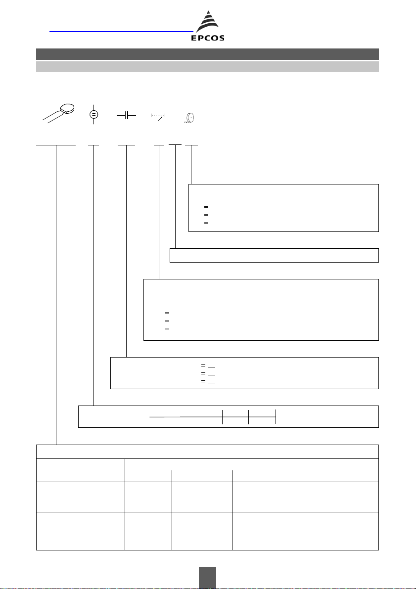
Ordering code system
B37979N 1 100 K 54
0
Internal coding
Capacitance tolerance
^
J
± 5 %
^
K ± 10 % (standard for C0G)
^
M ± 20 % (standard for X7R and Z5U (Y5U))
Packaging
^
51 cardboard tape, reel packing (360-mm reel)
^
54 Ammo packing (standard)
^
00 bulk
Leaded
Rated voltage
Type and size
With radial leads
EIA standard
Lead spacing 2,5 mm
Lead spacing 5,0 mm
´ 5,0 ´ 2,5
5,5
6,5
´ 5,0 ´ 2,5
5,5
´ 5,0 ´ 2,5
´ 5,0 ´ 2,5
6,5
´ 7,5 ´ 2,5
9,0
1
Code
101
222
473
^
10 · 10
^
22 · 10
^
47 · 10
pF = 100 pF
2
pF = 2,2 nF
3
pF = 47 nF
50 100
51
Capacitance, coded
(example)
Rated voltage [VDC]
Temperature characteristic
C0G X7R Z5U (Y5U)
B37979N B37981M B37982N
B37986N B37987M B37988N
B37979G B37981F B37982G
B37986G B37987F B37988G
— B37984M B37985N
152 10/02

Multilayer Ceramic Capacitors
C0G
Features
■ Good thermal stability
■ High insulation resistance
■ Low dissipation factor
■ Low inductance
Applications
■ Resonant circuits
■ Filter circuits
■ Timing elements
■ Coupling and filtering, particularly in RF circuits
Termination
■ Parallel wire leads, iron-nickel, tinned
■ Crimped leads
■ Non-standard lead lengths on request
Marking
■ Rated capacitance, tolerance, manufacturer’s logo,
ceramic material, voltage
Delivery mode
■ Cardboard tape in Ammo packing (standard)
■ Cardboard tape on 360-mm reel or bulk on request
Leaded
Electrical data
Temperature characteristic C0G
Climatic category (IEC 60068-1) 55/125/56
Standard EIA
Dielectric Class 1
Rated voltage V
Test voltage V
Capacitance range / E series C
Temperature coefficient 0
Dissipation factor (limit value) tan
Insulation resistance1) at + 25 °C R
Insulation resistance1) at +125 °C R
50, 100 VDC
R
2,5 · VR/5 s VDC
test
10 pF … 10 nF (E12)
R
± 30 · 10
d < 1,0 · 10
> 10
ins
> 10
ins
–6
/K
–3
5
4
Time constant1) at + 25 °C t > 1000 s
1)
Time constant
Operating temperature range T
at +125 °C t > 100 s
–55 … +125 °C
op
Ageing none
1) For CR > 10 nF the time constant t = C · R
is given.
ins
153 10/02
MW
MW
C0G
Multilayer Ceramic Capacitors
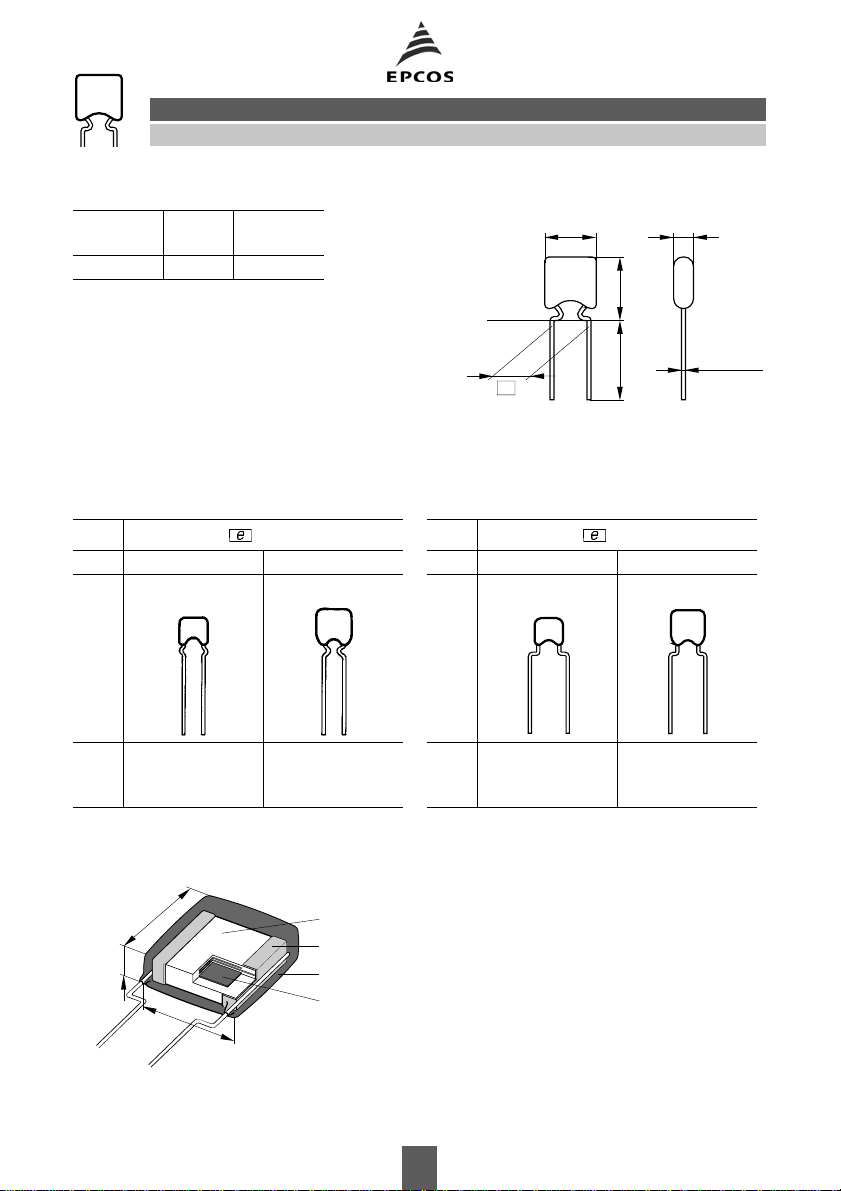
Capacitance tolerances Dimensional drawing
Code letter J K
To le r a nc e
±5% ±10%
(standard)
bs
h30+5
**)
*)
e
*)
Lead length for bulk packaging
**)
Seating plane in acc. with IEC 600717
Dimensions (mm)
Lead spacing = 2,5 +0,6/ – 0,1 mm Lead spacing = 5,0 +0,6/ – 0,1 mm
Type B37979N B37986N Type B37979G B37986G
C0G
ø0,50±0,05
KKE0456-R-E
h
5,5
max
b
5,0
max
s
2,5
max
Termination
h
s
6,5
5,0
2,5
5,5
h
max
b
5,0
max
s
2,5
max
6,5
5,0
2,5
Ceramic dielectric
Termination
Encapsulation
b
Metal layers
KKE0457-Z-E
154 10/02
Multilayer Ceramic Capacitors
C0G
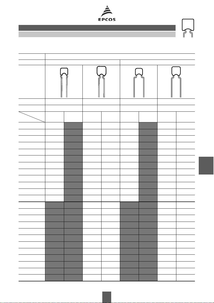
Product range leaded capacitors
C0G
Lead spacing 2,5 mm 5,0 mm
h
´ b ´ s (mm) 5,5 ´ 5,0 ´ 2,5 6,5 ´ 5,0 ´ 2,5 5,5 ´ 5,0 ´ 2,5 6,5 ´ 5,0 ´ 2,5
Type B37979N B37986N B37979G B37986G
C
R
VR (VDC)
50 100 50 100 50 100 50 100
10 pF
12 pF
15 pF
18 pF
22 pF
27 pF
33 pF
39 pF
47 pF
56 pF
68 pF
82 pF
100 pF
120 pF
150 pF
180 pF
220 pF
270 pF
330 pF
390 pF
470 pF
560 pF
680 pF
820 pF
C0G
155 10/02

C0G
Multilayer Ceramic Capacitors
Product range leaded capacitors
C0G
Lead spacing 2,5 mm 5,0 mm
h
´ b ´ s (mm) 5,5 ´ 5,0 ´ 2,5 6,5 ´ 5,0 ´ 2,5 5,5 ´ 5,0 ´ 2,5 6,5 ´ 5,0 ´ 2,5
Type B37979N B37986N B37979G B37986G
C
R
VR (VDC)
50 100 50 100 50 100 50 100
1,0 nF
1,2 nF
1,5 nF
1,8 nF
2,2 nF
2,7 nF
3,3 nF
3,9 nF
4,7 nF
5,6 nF
6,8 nF
8,2 nF
10, nF
C0G
156 10/02

Multilayer Ceramic Capacitors
C0G
Ordering codes and packing for C0G, 50 VDC, lead spacing 2,5 mm
Ammo packing Reel packing Bulk
^ ^ ^
C
R
Ordering code
1)
** 54 ** 51 ** 00
pcs pcs/reel pcs
B37979, 50 VDC, 5,5 × 5,0 × 2,5 mm
100, pF B37979N5101K0** 2500 2500 2000
120, pF B37979N5121K0** 2500 2500 2000
150, pF B37979N5151K0** 2500 2500 2000
180, pF B37979N5181K0** 2500 2500 2000
220, pF B37979N5221K0** 2500 2500 2000
270, pF B37979N5271K0** 2500 2500 2000
330, pF B37979N5331K0** 2500 2500 2000
390, pF B37979N5391K0** 2500 2500 2000
470, pF B37979N5471K0** 2500 2500 2000
560, pF B37979N5561K0** 2500 2500 2000
680, pF B37979N5681K0** 2500 2500 2000
820, pF B37979N5821K0** 2500 2500 2000
1,0 nF B37979N5102K0** 2500 2500 2000
1,2 nF B37979N5122K0** 2500 2500 2000
1,5 nF B37979N5152K0** 2500 2500 2000
1,8 nF B37979N5182K0** 2500 2500 2000
2,2 nF B37979N5222K0** 2500 2500 2000
B37986, 50 VDC, 6,5 × 5,0 × 2,5 mm
2,7 nF B37986N5272K0** 2500 2500 2000
3,3 nF B37986N5332K0** 2500 2500 2000
3,9 nF B37986N5392K0** 2500 2500 2000
4,7 nF B37986N5472K0** 2500 2500 2000
5,6 nF B37986N5562K0** 2500 2500 2000
6,8 nF B37986N5682K0** 2500 2500 2000
8,2 nF B37986N5822K0** 2500 2500 2000
10, nF B37986N5103K0** 2500 2500 2000
C0G
1) The table contains the ordering codes for the standard capacitance tolerance.
For other available capacitance tolerances see page 154.
157 10/02

C0G
Multilayer Ceramic Capacitors
Ordering codes and packing for C0G, 50 VDC, lead spacing 5,0 mm
Ammo packing Reel packing Bulk
^ ^ ^
C
R
Ordering code
1)
** 54 ** 51 ** 00
pcs pcs/reel pcs
B37979, 50 VDC, 5,5 × 5,0 × 2,5 mm
100, pF B37979G5101K0** 2500 2500 2000
120, pF B37979G5121K0** 2500 2500 2000
150, pF B37979G5151K0** 2500 2500 2000
180, pF B37979G5181K0** 2500 2500 2000
220, pF B37979G5221K0** 2500 2500 2000
270, pF B37979G5271K0** 2500 2500 2000
330, pF B37979G5331K0** 2500 2500 2000
390, pF B37979G5391K0** 2500 2500 2000
470, pF B37979G5471K0** 2500 2500 2000
560, pF B37979G5561K0** 2500 2500 2000
680, pF B37979G5681K0** 2500 2500 2000
820, pF B37979G5821K0** 2500 2500 2000
1,0 nF B37979G5102K0** 2500 2500 2000
1,2 nF B37979G5122K0** 2500 2500 2000
1,5 nF B37979G5152K0** 2500 2500 2000
1,8 nF B37979G5182K0** 2500 2500 2000
2,2 nF B37979G5222K0** 2500 2500 2000
B37986, 50 VDC, 6,5 × 5,0 × 2,5 mm
2,7 nF B37986G5272K0** 2500 2500 2000
3,3 nF B37986G5332K0** 2500 2500 2000
3,9 nF B37986G5392K0** 2500 2500 2000
4,7 nF B37986G5472K0** 2500 2500 2000
5,6 nF B37986G5562K0** 2500 2500 2000
6,8 nF B37986G5682K0** 2500 2500 2000
8,2 nF B37986G5822K0** 2500 2500 2000
10, nF B37986G5103K0** 2500 2500 2000
C0G
1) The table contains the ordering codes for the standard capacitance tolerance.
For other available capacitance tolerances see page 154.
158 10/02

Multilayer Ceramic Capacitors
C0G
Ordering codes and packing for C0G, 100 VDC, lead spacing 2,5 mm
Ammo packing Reel packing Bulk
^ ^ ^
C
R
Ordering code
1)
** 54 ** 51 ** 00
pcs pcs/reel pcs
B37979, 100 VDC, 5,5 × 5,0 × 2,5 mm
10, pF B37979N1100K0** 2500 2500 2000
12, pF B37979N1120K0** 2500 2500 2000
15, pF B37979N1150K0** 2500 2500 2000
18, pF B37979N1180K0** 2500 2500 2000
22, pF B37979N1220K0** 2500 2500 2000
27, pF B37979N1270K0** 2500 2500 2000
33, pF B37979N1330K0** 2500 2500 2000
39, pF B37979N1390K0** 2500 2500 2000
47, pF B37979N1470K0** 2500 2500 2000
56, pF B37979N1560K0** 2500 2500 2000
68, pF B37979N1680K0** 2500 2500 2000
82, pF B37979N1820K0** 2500 2500 2000
100, pF B37979N1101K0** 2500 2500 2000
120, pF B37979N1121K0** 2500 2500 2000
150, pF B37979N1151K0** 2500 2500 2000
180, pF B37979N1181K0** 2500 2500 2000
220, pF B37979N1221K0** 2500 2500 2000
270, pF B37979N1271K0** 2500 2500 2000
330, pF B37979N1331K0** 2500 2500 2000
390, pF B37979N1391K0** 2500 2500 2000
470, pF B37979N1471K0** 2500 2500 2000
560, pF B37979N1561K0** 2500 2500 2000
680, pF B37979N1681K0** 2500 2500 2000
820, pF B37979N1821K0** 2500 2500 2000
1,0 nF B37979N1102K0** 2500 2500 2000
B37986, 100 VDC, 6,5 × 5,0 × 2,5 mm
1,2 nF B37986N1122K0** 2500 2500 2000
1,5 nF B37986N1152K0** 2500 2500 2000
1,8 nF B37986N1182K0** 2500 2500 2000
2,2 nF B37986N1222K0** 2500 2500 2000
C0G
1) The table contains the ordering codes for the standard capacitance tolerance.
For other available capacitance tolerances see page 154.
159 10/02

C0G
Multilayer Ceramic Capacitors
Ordering codes and packing for C0G, 100 VDC, lead spacing 5,0 mm
Ammo packing Reel packing Bulk
^ ^ ^
C
R
Ordering code
1)
** 54 ** 51 ** 00
pcs pcs/reel pcs
B37979, 100 VDC, 5,5 × 5,0 × 2,5 mm
10, pF B37979G1100K0** 2500 2500 2000
12, pF B37979G1120K0** 2500 2500 2000
15, pF B37979G1150K0** 2500 2500 2000
18, pF B37979G1180K0** 2500 2500 2000
22, pF B37979G1220K0** 2500 2500 2000
27, pF B37979G1270K0** 2500 2500 2000
33, pF B37979G1330K0** 2500 2500 2000
39, pF B37979G1390K0** 2500 2500 2000
47, pF B37979G1470K0** 2500 2500 2000
56, pF B37979G1560K0** 2500 2500 2000
68, pF B37979G1680K0** 2500 2500 2000
82, pF B37979G1820K0** 2500 2500 2000
100, pF B37979G1101K0** 2500 2500 2000
120, pF B37979G1121K0** 2500 2500 2000
150, pF B37979G1151K0** 2500 2500 2000
180, pF B37979G1181K0** 2500 2500 2000
220, pF B37979G1221K0** 2500 2500 2000
270, pF B37979G1271K0** 2500 2500 2000
330, pF B37979G1331K0** 2500 2500 2000
390, pF B37979G1391K0** 2500 2500 2000
470, pF B37979G1471K0** 2500 2500 2000
560, pF B37979G1561K0** 2500 2500 2000
680, pF B37979G1681K0** 2500 2500 2000
820, pF B37979G1821K0** 2500 2500 2000
1,0 nF B37979G1102K0** 2500 2500 2000
B37986, 100 VDC, 6,5 × 5,0 × 2,5 mm
1,2 nF B37986G1122K0** 2500 2500 2000
1,5 nF B37986G1152K0** 2500 2500 2000
1,8 nF B37986G1182K0** 2500 2500 2000
2,2 nF B37986G1222K0** 2500 2500 2000
C0G
1) The table contains the ordering codes for the standard capacitance tolerance.
For other available capacitance tolerances see page 154.
160 10/02

Multilayer Ceramic Capacitors
C0G
Typical characteristics
Capacitance change
temperature T (tolerance range )
1,0
%
∆C
0,8
C
25
0,6
0,4
0,2
0
_
0,2
_
0,4
_
0,6
_
0,8
_
1,0
__
55
40 20
DC/C
versus
25
_
020406080˚C
KKE0107-F
C0G
Capacitance change DC/C0 versus
superimposed DC voltage V
KKE0368-9
∆C
C
0,5
%
0
0,3
0,2
0,1
0
_
0,1
_
0,2
_
0,3
_
0,4
_
120
0,5
T
200
40 60 80 V 100
V
Insulation resistance R
versus
ins
temperature T
8
10
M
Ω
R
ins
6
10
5
10
4
10
3
10
2
10
0 20 40 60 80 100 ˚C 140
KKE0129-B
T
Dissipation factor tan d versus
temperature T
_
2
10
tan
δ
_
3
10
_
4
10
_
5
10
_
60_40_20
0 20 40 60 80 100 ˚C 140
161 10/02
KKE0118-V
T

C0G
Typical characteristics
Impedance |Z | versus
frequency f
3
10
Ω
Z
2
10
1
2
10
10
1
0
3
4
5
KKE0338-M
Multilayer Ceramic Capacitors
Capacitance change
time t
5
%
C∆
C
1
0
_
5
_
10
DC/C
versus
1
C0G
KKE0100-S
_
1
10
_
2
10
10
0
10
1
1: Chip
2: 1,5 mm lead length
3: 5,0 mm lead length
4: 10,0 mm lead length
5: 20,0 mm lead length
10
_
15
_
20
2
MHz
10
3
10
0
f
10
1
10
2
3
10
h
t
162 10/02

Published by EPCOS AG
Corporate Communications, P.O. Box 80 17 09, 81617 Munich, GERMANY
++49 89 636 09, FAX (0 89) 636-2 26 89
(
EPCOS AG 2002. Reproduction, publication and dissemination of this brochure and the information contained therein without
EPCOS’ prior express consent is prohibited.
Purchase orders are subject to the General Conditions for the Supply of Products and Services of the Electrical and Electronics
Industry recommended by the ZVEI (German Electrical and Electronic Manufacturers’ Association), unless otherwise agreed.
This brochure replaces the previous edition.
For questions on technology, prices and delivery please contact the Sales Offices of EPCOS AG or the international Representa-
tives.
Due to technical requirements components may contain dangerous substances. For information on the type in question please
also contact one of our Sales Offices.
 Loading...