

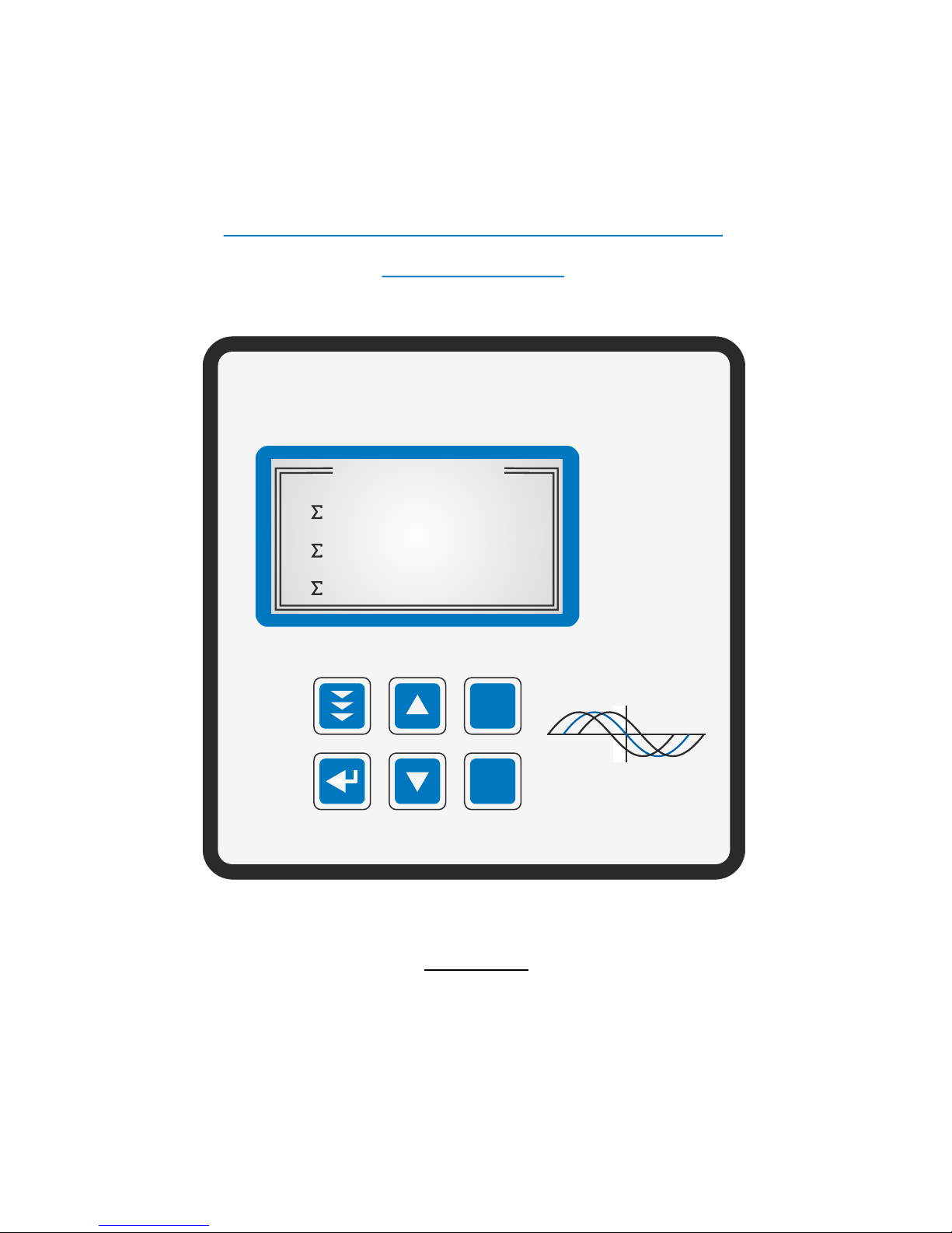
Power Factor Controller
BR 7000
Manual
Version 1.1 E
Power Factor
Controller
BR 7000
Auto
Program
Manual
Service
Enter
OK
Power Quality Solutions
HELP
ESC
AUTO-MODE 2/2
14
137
140
kvar
kW
kVA
Q
P
S
cos
ϕ

!
CAUTIONS:
1. High voltage !
2. BR7000 may only be used indoor !
3. Make sure that the discharge time set in the controller matches
the capacitor discharge time !

CONTENTS
Section 1 General p.3
Section 2 Installation and instructions for usage p.4
Section 3 Connection alternatives measuring voltage p.6
and measuring current
Section 4 Display functions p.8
Section 5 Display of grid parameters p.9
Section 6 PROGRAM-MODE / Manual programming p.11
6.1 Programming lock p.18
6.2 QUICK-Program p.19
Section 7 Automatic initialization p.20
Section 8 Automatic test run p.21
Section 9 HELP-function / actual assignment of outputs p.21
Section 10 MANUAL OPERATION p.23
Section 11 SERVICE MENU / Error storage p.24
Section 12 EXPERT MODE
12.1 Expert-Mode 1 p.25
12.2 Expert-Mode 2 p.27
Section 13 Control principle p.28
Section 14 Interfaces p.29
14.1 ASCII -protocol p.30
14.2 Controller coupling p.30
14.3 Windows-software for PC p.31
Section 15 Alarm relay / Error messages p.32
Section 16 Display-editor p.32
Section 17 OSCI-MODE p.32
Section 18 Maintenance and warranty p.32
Appendixes/ Tables:
Annex 1 Troubleshooting p.33
Annex 2 Technical data p.35
Annex 3 Factory settings p.37
Annex 4 Control series table p.39
Control series editor
Annex 5 Register MODBUS protocol p.40
Annex 6 Operation diagram p.43
- 2 -
Rev.: 04.2013

Section 1: GENERAL
The power factor controller BR7000 is the consequent follow-up development of the well
proven series BR6000.
The main distinctive feature is the new 3-phases measuring system. Due to the 3-phases
recording of voltage and current the device allows a convenient usage as grid measuring
device and as power factor controller.
All measuring values can be edited and may be displayed in big letters for easier
readability.
2 interfaces are standard. By means of the comfortable windows-software that is included
in the delivery and by using one interface for a connection to a PC the execution and
evaluation of grid measurements is possible. The second interface can be used for
customer specific purposes.
Used as PF-controller various control modes are available. They allow not only to control
according to the phase with the highest load or the average demand of the phases, but
also to realize a real single-phase control (balancing) or a mix of balancing and
conventional three-phases-control.
All well proven functions of the BR6000-series are available for the BR7000; for example
the control series editor, the automatic initialization etc. For an easy usage the concept of
graphic menu navigation has mainly been adapted. New are amongst others an
integrated help (HELP-button) and the possibility to jump back in the programming menu
by an additional ESCape-button.
The usage of a fully graphic support display allows an additional Oscilloscope-Mode where
the phases (half waves) of voltage and current can graphically be displayed.
R 3 x 5 free programmable switching outputs
R 1 alarm relay, 1 programmable message relay, 1 relay for the cabinet fan
R Operating voltage: 110 ... 230VAC (+/-15%)
R Measuring voltage: 3 x 30 ... 440 VAC (L-N) / 50...760 V (L-L)
R Measuring current: 3 x 5A / 1A
R Pre-programmed control series and control series editor
R Illuminated graphic display 128 x 64 dot, graphical menu navigation
R 4-quadrant-operation
R Automatic initialization possible
R Measuring of capacitor current possible
R Three-phase display of various grid parameters ( U, I, F, Q, P, S Delta Q ... )
R Switch over to large display possible
R Display up to 31st harmonic of voltage and current
R Simultaneous graphical display 1 period of voltage and current in Osci-mode
R Monitoring of temperature and particular capacitor output
R Storage of maximum grid parameters and switching operations/switch on times of
capacitors with time stamp
R Manual/automatic operation
R Programming of fixed steps or mascing of particular outputs possible
R Control possible as 3-phase, 1-phase or mixed-mode
R Display of different error messages
R Error storage
R Complete 2nd parameter set programmable
R 2 integrated separate interfaces
R Integrated clock, several timers possible
R Integrated help-function/plain text
R Panel-mounted instrument 144 x 144 x 60 mm
- 3 -

- 4 -
Section 2: INSTALLATION AND INSTRUCTIONS FOR USAGE
The BR7000 is designed as panel mounting instrument in PFC-systems. This requires a
cut out of 138 x 138 mm according to DIN 43700 / IEC 61554. The controller has to be
inserted from the front and fixed with the clamps (included in delivery). The device may
only be installed by qualified personnel and may only be operated according the given
safety regulations. In addition the relevant legal and safety instructions have to be
obeyed.
The measuring input is designed for 1- and 3-phase grids with or without neutral
conductor. The maximum measuring voltage is 440V+ (L-N) / 760V ~ (L-L).
The supply voltage is 110...230 V +/-15%.
Wiring connections must be suitable for the particular voltages. Input leads have to be
protected by over-current-protection devices. The supply voltage must be protected by a
fuse; it must be possible to switch off the supply voltage by a separator.
The BR7000 must not be operated without protective earth contactor connected!
Before connecting the BR7000, it has to be checked that all connections are at zero
potential; current transformers have to be short circuited. Correct phasing of measuring
voltage and measuring current have to be checked. The measuring current circuits must
2
be wired with minimum 2.5 mm Cu.
Terminals may only be plugged when de-energized!
Attention!
During single-phase operation the coil voltage for the capacitor contactors must be drawn
from the same phase as the measuring voltage as only the measuring voltage is
monitored. (Protection against direct re-switching of contactors during a short-term
single-phase voltage drop.)
The controller may only be operated when installed. The complete programming of all
application-specific parameters is done according chapter programming. Then the device
is set to automatic operation by pushing the operation mode button. The controller is now
ready for operation.
Operating the controller without following to these operating instructions may be harmful
and dangerous!
!
!
!
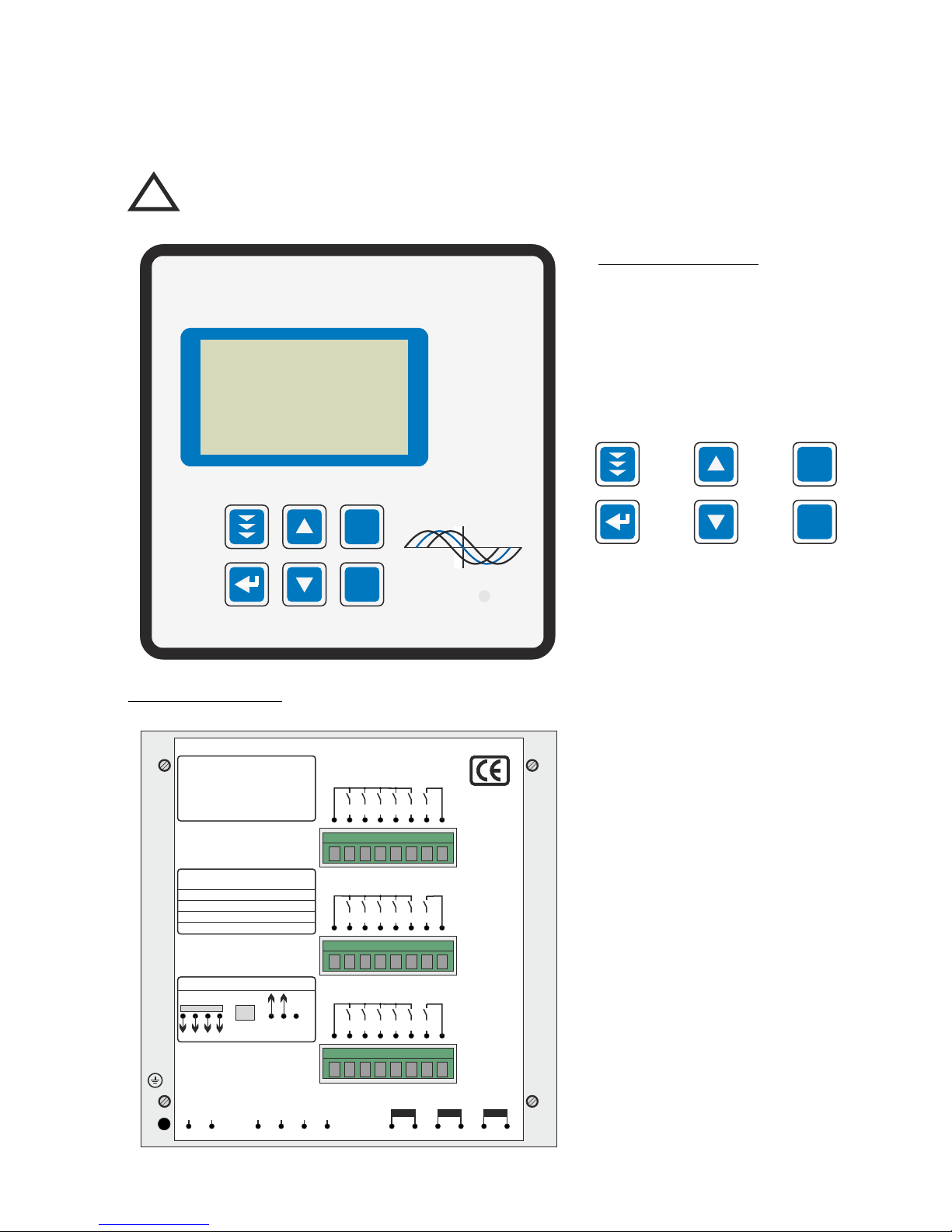
BR 7000 rear view
Operating mode:
- Automatic
- Program.
- Manual oper.
- Service
- Expert Mode
- Osci - Mode
- Display Editor
ENTER/ OK
Confirmation
storage of
values
Increase
selected
parameter
HELP
opens
Help pages
Reduce
selected
parameter
Escape
previous
page/value
in the display
- 5 -
BR 7000 front view
The controller is supplied for a standard operating voltage of 110...230VAC (+/-15%), a
measuring voltage of 30...440 V~ (L-N) resp. 50...760V~ (L-L), 50/60Hz, and a
measuring current of 5A or 1A (programmable). A voltage converter is required for
different operating voltages.
Caution!
Voltages which exceed the allowed voltage range can damage the
device !
!
Power Factor
Controller
BR 7000
Auto
Program
Manual
Service
Enter
OK
Power Quality Solutions
HELP
ESC
HELP
ESC
Power factor controller BR7000
Type: BR7000-R
Meas voltage: 50 - 760VAC 50/60Hz
Supply voltage:110 - 230VAC 50/60Hz
Ser.Nr.: 0815 / 2009
P1
P2
P3
K1
K6
K11
K2
K7
K12
K3
K8
K13
K4
K9
K14
K5
K10
K15
K21
K22
K23
Meas.current
k L1 l
Supply voltage
110...230V~
Measuring voltage
30 ... 440V L-N
Output 11-15
Output 6-10
Output 1-5
Switching outputs:
Fan relay
Message relay
Alarm relay
Meas.current
k L2 l
Meas.current
k L3 l
Interface 1
Contact assignment 2nd terminal at bottom
Interface 2
External input
230V~
GND B A PE
L1 N L1 L2 L3 N
The allocation of switching outputs K1…K15
to the capacitors complies to the selected
connection variant and the desired
CONTROL-MODE
(Programming/point 2)
Especially in ”Mixed Mode“ where some
outputs are used for single phase capacitors,
others for 3-phase-capacitors the proper
connection must be assured!
In the “HELP”-menu the BR7000 directly
displays the actual correct allocation of
outputs (AUTO-MODE: Help-page 7-9).
For examples also see chapter 9.
cos
ϕ
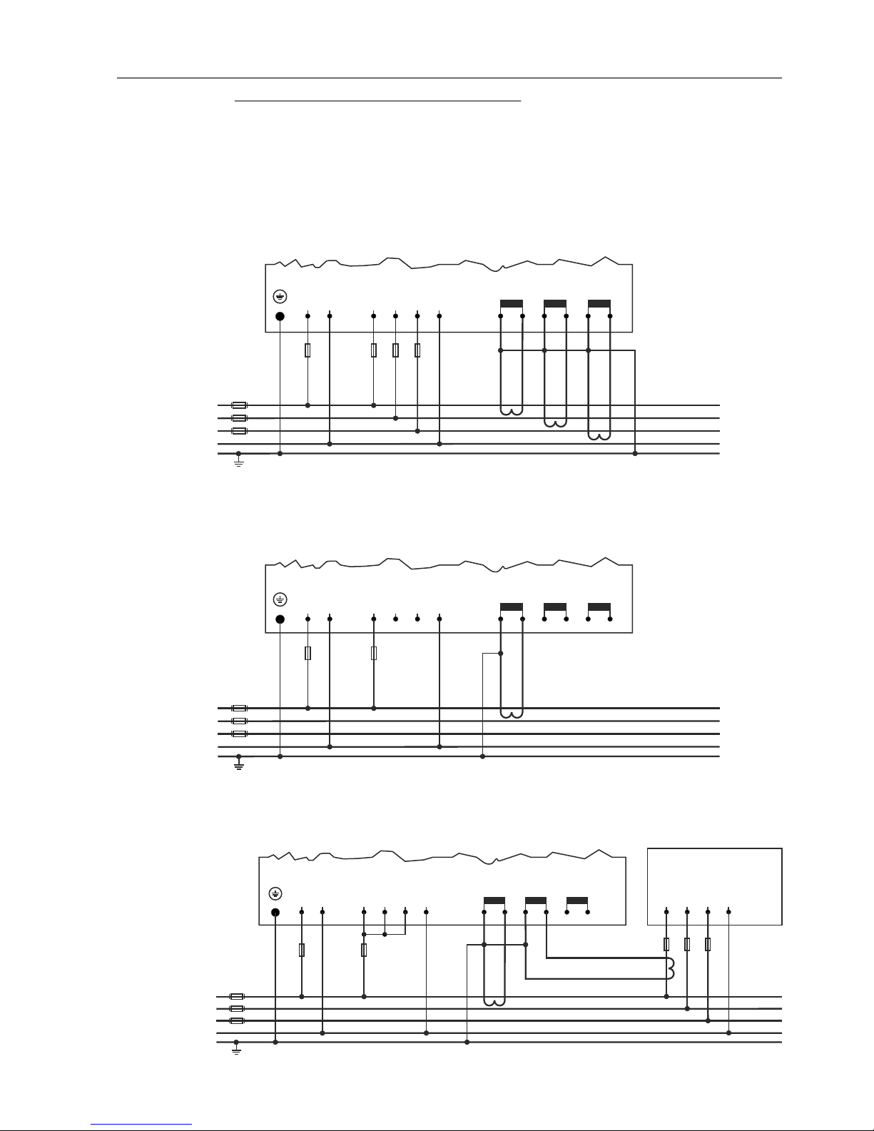
Section 3: CONNECTION ALTERNATIVES MEASURING VOLTAGE
AND MEASURING CURRENT
According to the existing grid and the desired operating mode (CONTROL-MODE
Programming) the BR7000 has to be connected accord. one of the following alternatives.
In grids without neutral conductor the connector N(PE) from meas.voltage at
the controller has to be connect with the PE of the grid !
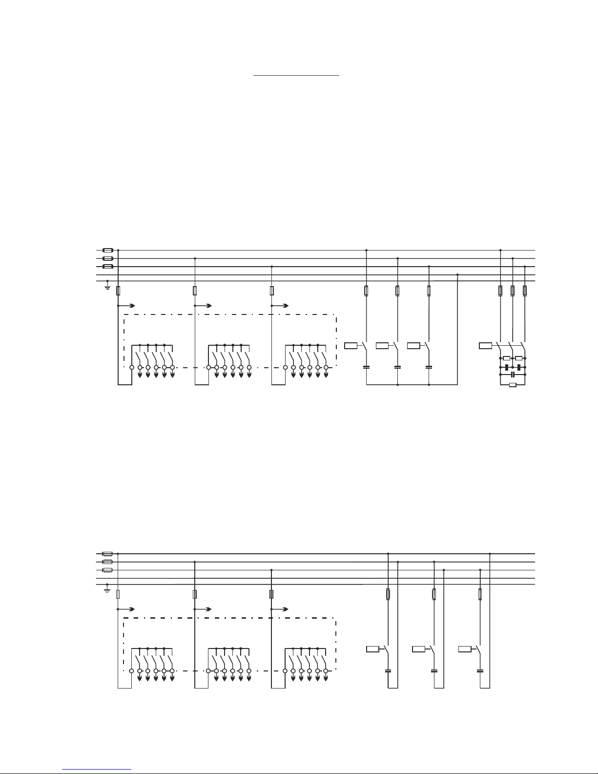
Alternative 1: measuring performed in each phase - 3 current transformers needed
Use: CONTROL-MODE: 1 - 4 (control modes see page 11)
BR7000
Alternative 2: single-phase measuring via current transformer in L1 Values extrapolated (balance assumed).
Measuring complies with conventional measuring for switching of three-phase capacitors.
Use: CONTROL-MODE 5
BR7000
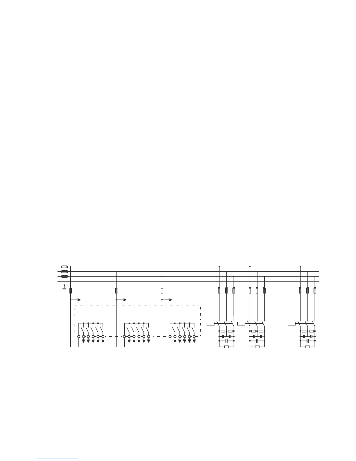
Alternative 3: single-phase measuring as alternative 2 , but with capacitor current measuring in the compensation
system for collection of real capacitor currents.
Use: CONTROL-MODE 6
BR7000
Reserve
PE
N
L2 (S)
L3 (T)
L1 (R)
( L1) ( N )
L1 L2 L3 N(PE)*
Supply voltage
110-230V~
Measuring voltage Um
Meas.current
L3
Meas.current
L2
Meas.current
L1
Load site
( L1) ( N )
L1 L2 L3 N(PE)*
Supply voltage
110-230V~
Measuring voltage Um
Meas.current
L3
Meas.current
L2
Meas.current
L1
L1 (R)
L2 (S)
L3 (T)
PE
N
Load site
- 6 -
( L1) ( N )
L1 L2 L3 N(PE)*
Supply voltage
110-230V~
Measuring voltage Um
Meas.current
L3
Meas.current
L2
Meas.current
L1
L1 (R)
L2 (S)
L3 (T)
PE
N
L1 L2 L3 N
P F C- system
- 7 -
kK k K
lL l L
Feed 1 Feed 2
K L K L
Measurement via sum current converter
P.F.Controller
Current
measurement
k l
k l
Example:
C.converter 1: 1000/5A
C.converter 2: 1000/5A
Sum-current converter: 5A+5A / 5A
C.converter ratio is: 2000 /5A
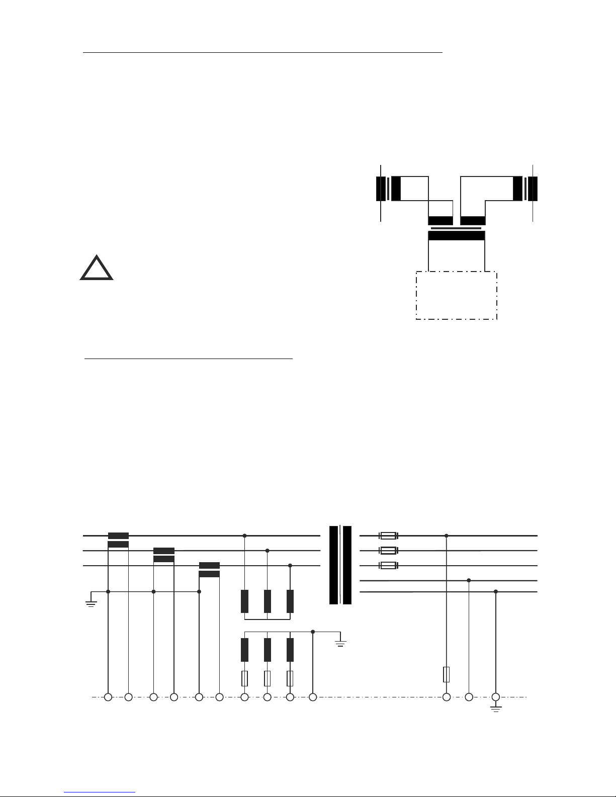
Connection of current transformer / sum current transformer
When installing the current converter, care should be taken to ensure that the load
current flows through it. The outputs of the compensation network must be installed
behind the current converter (in the direction of current flow). If the is connected
up via sum-current converters, the overall conversion ratio is entered.
Current converter clamps should be grounded on one side!
Caution!
Current converter clamps should
be grounded on one side !
The secondary clamps of the CT
have to be short circuited before
current leads are iterrupted !
BR7000
!
BR7000 in High Voltage Application
The example shows the connection of BR7000 in HV-application.
The measuring current is taken off primary via X/1A transformer. Measuring voltage
produced via transformer 20000/100 V. In this case, the BR7000 has to be programmed
as follows:
4 I-CONVERTER sek: X / 1A
14 MEASUR.VOLTAGE: 100 V
15 V-CONVERTER: 20kV / 100 V
L1 (R)
L1 (R)
L2 (S)
L2 (S)
L3 (T)
L3 (T)
N
Meas.current
Im (X/1A)
supply
voltage
Ub
Meas voltage
Um
BR 7000
PE
Meas.current Meas. voltage Um
Supply voltage Ub
L1 L2 L3
L1 L2 L3 N
L1 N
HIGH VOLTAGE LOW VOLTAGE
20 kV / 400 V
20000
100
Section 4: DISPLAY - FUNCTIONS
After the operating voltage has been switched on, the BR7000 briefly indicates with
description and software-version before changing to automatic operation.
Actual values and symbols of the particular operation state are shown in the display.
In the automatic operation (standard) capacitor steps are automatically switched on or
off to reach the pre-set target cos-phi. This happens when the required reactive power is
higher than the value of the smallest capacitor step.
Example 1: Automatic operation
L1...L3: Individual compensation by single-phase capacitors
- 8 -
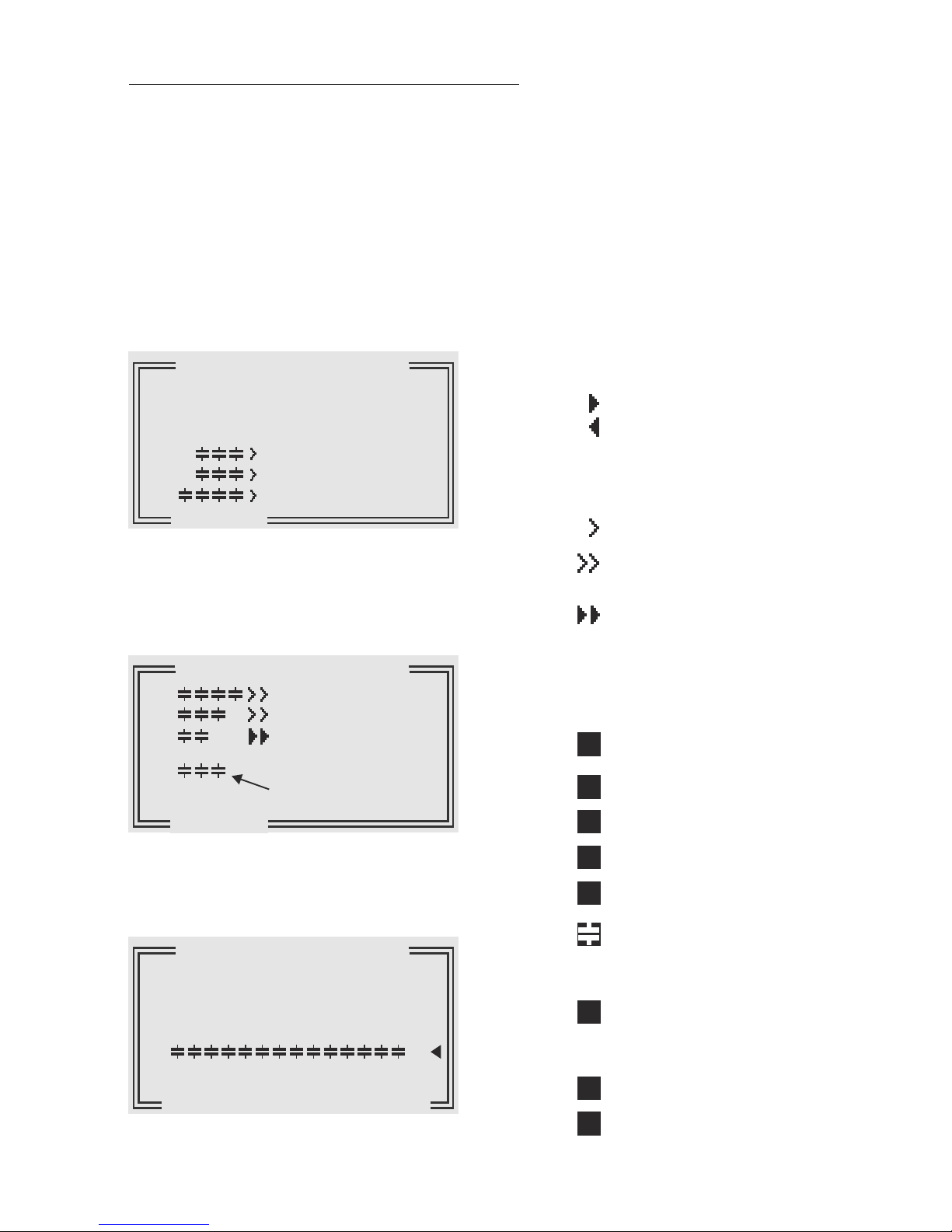
Number of switching outputs until end stop.
Here: 15 three-phase capacitors, end-stop: 15
Control direction is symbolized by a
compact arrow:
Connecting-in
Connecting-out
The connecting-in arrow is always
located after the maximum possible
number of stages (end stop)
An open arrow indicates that the
required blocking time (Discharge time)
is running before an impending
switching step
A double arrow symbolizes switching of
several branches
The sigma-sign indicates the threephase-value (mean-value) resp.
activated three-phase-capacitors
Alarm relay activated
(declines in case of error)
Message relay activated: “SUPPLY”
Message relay activated:“Undercurrent”
Message relay aktivated: “Harmonics”
FAN-relay: ON
The particular capacitor outputs are
permanently monitored. Inverse display
= capacitor out of range
Display of 2nd parameter-set
Supply display (i.e.generator operation)
nd
2 Target-cos phi activated by timer
nd
2 Target-cos phi activated by supply
S
A
U
H
F
2
T
é
é
Example 2: Automatic operation (Mixed Mode)
L1...L3: phase wise compensation by
single phase capacitors
Σ: Three-phase capacitors activated
Example 3: Automatic operation
Measuring in one phase
Controlling of 15 three-phase-capacitors
Σ
AUTO-MODE 1/2
cosϕ 0.869 IND
cosϕ 0.869 IND
cosϕ 0.869 IND
cosϕ 0.917 CAP
L1
L1
L2
L2
L3
L3
1 2 3 4
Σ
Σ
Σ
AUTO-MODE 1/3
AUTO-MODE 1/2
L1
L2
L3
1 2 3 4
1 2 3 4 5 6 7 8 9
10 11 12 13 14 15
control direction
(here: connected-in)
active capacitor
branches
Section 5: DISPLAY OF GRID PARAMETERS
5.1 Display of 3 selected grid parameters
In Auto-Mode, button é leads to display mode 1. Here 3 (free selectable) grid parameters
are displayed in large letters. The selection and storage of these values is done in the
Display- Editor.
Example: Display mode 1:
Desired values selected in the
Display Editor (see section 16 )
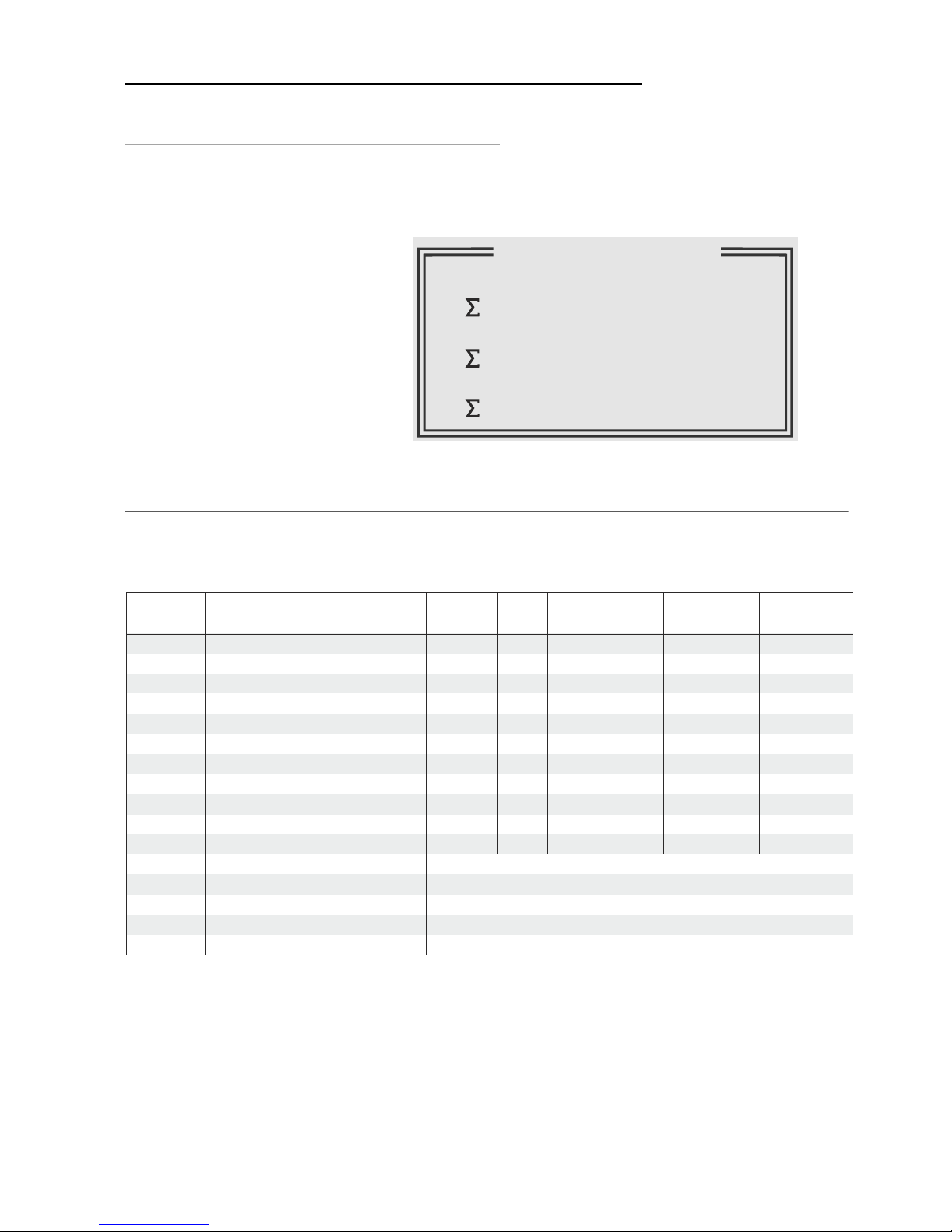
5.2 Display of particular grid parameters (from AUTO-MODE by pressing ENTER)
By repeated activation of the “ENTER”-button (in automatic operation) several grid
parameters can be displayed (s. table below):
Action Display Unit in% large display Bargraph 3-phase
possible possible
ENTER 1 LINE VOLTAGE V x x
ENTER 2 APPARENT CURRENT A x x x
ENTER 3 REACTIVE POWER kvar x x x
ENTER 4 ACTIVE POWER kW x x x
ENTER 5 APPARENT POWER kVA x x x
ENTER 6 DIFF. kvar to target kvar x x x
ENTER 7 FREQUENCY Hz x x
ENTER 8 TEMPERATURE °C / °F x
ENTER 9 3.-31. HARMONICS V/ I x x x
ENTER 10 HARMONICS THD-V/I x x x
ENTER 11 Comp.- power (only at real capacitor current measurement)
ENTER 12 ENERGY kvarh / kWh
ENTER 13 TIME / DATE é / ê change the date format
ENTER 14 Software version
ENTER return to: 1
Buttons é / ê change the display format:
The values can be displayed in their unit, in % or as large display resp. bar chart.
Examples, see next page.
- 9 -
AUTO-MODE 2/2
14
137
140
kvar
kW
kVA
Q
P
S
=== DISPLAY ===
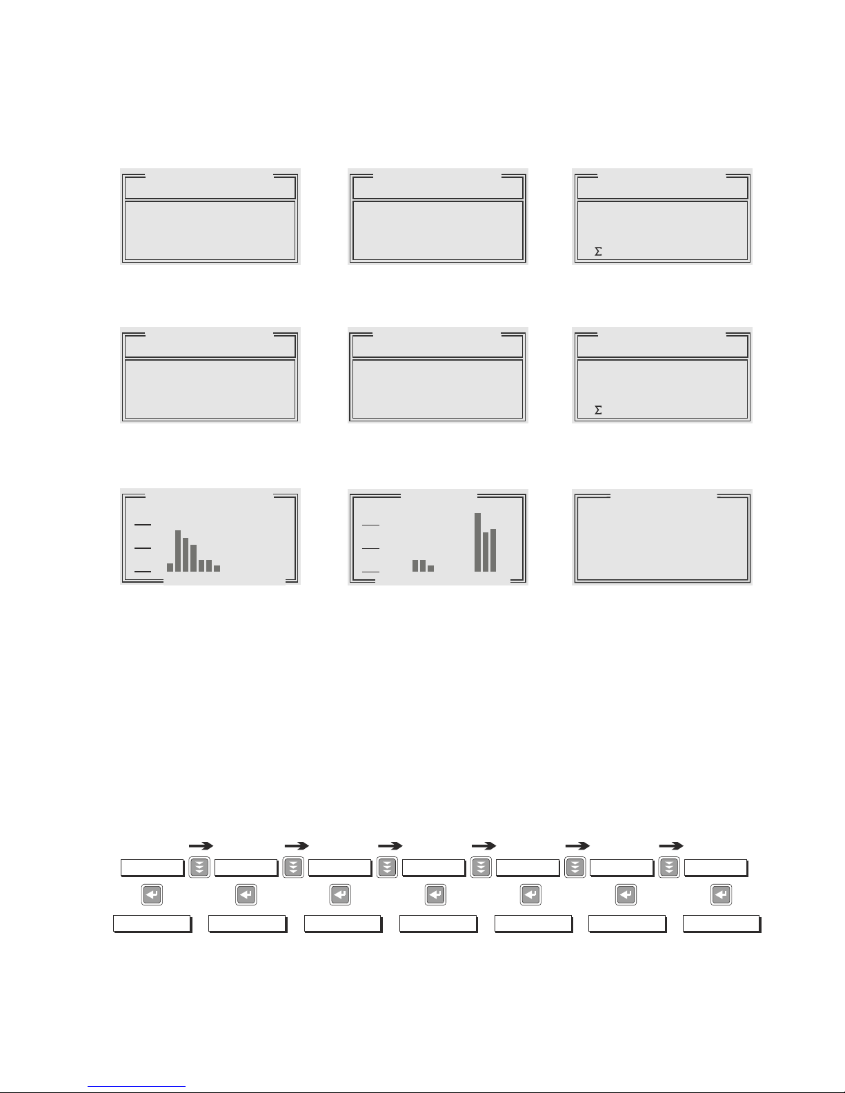
Examples of different displays:
VOLTAGE 3-phas. CURRENT: 3-phas. REACTIVE PWR 3-phas.
HARMONICS in % TEMPERATURE °C REACTIVE PWR in %
LARGE LETTERS
HARMONICS diagram THD V/I as bar diagram REACTIVE POWER
LARGE LETTERS
- 10 -
Repeated pressing of the "Operating Mode” key activates the various menus in sequence:
Automatic operation - Programming - Manual (manual operation)- Service - Expert
mode - OsciMode - DisplayEditor and back to Auto.
AUTO-MODE
to display operation to programming to manual operation to value buffer special functions to graphic. mode display-functions
PROGRAMMING
MANUAL-MODE
SERVICE EXPERT-MODE OSZI - MODE
DISPLAY-EDITOR
DISPLAY 7/9
8 HARMONICS [3.]
L1 V 0.4% I 0.5%
L2 V 1.4% I 0.8%
L3 V 1.4% I 0.7%
DISPLAY 3/4
TEMPERATURE
25 °C
DISPLAY 1/3
1 LINE VOLTAGE
L1-N 233 V
L2-N 233 V
L3-N 233 V
24VDC 24 V
DISPLAY 3/3
25
25
25
kvar
kvar
kvar
Q1
Q2
Q3
ANZEIGE 1/3
2 APPAR.CURRENT
L1 235 A
L2 133 A
L3 133 A
DISPLAY 1/2
3 REACTIVE POWER
L1 71 kvar
L2 23 kvar
L3 22 kvar
116 kvar
DISPLAY 2/3
3 REACTIVE POWER
L1 31 %
L2 10 %
L3 10 %
17 %
HARMONICS [V-1]
1.0%
0.5%
0%
35 79
11 13 15 17 19 21 23 25 27 29 31
THD 1/2
20%
10%
0%
THD V 1 2 3 THD I 1 2 3
DISPLAY 1/3
Section 6: PROGRAM-MODE (manual programming)
Pressing the button “Operation Mode“ one time switches from automatic operation to the
program mode.
The upper part of the display always shows the parameter, the adjustable values are
shown in the lower part. Editable values are generally given in square brackets. Changes
of these values can be done by the buttons é / ê. By pressing the “ENTER-button” the
value is stored. Pressing the “ESC”-button allows to go one step back (without storing).
1 LANGUAGE
This selects the language of the operating menu
[GERMAN, ENGLISH, SPANISH, RUSSIAN, TURKISH]
2 CONTROL-MODE [1...6]
CONTROL-MODE [1]:
3-phase measuring / max. 3x5 single phase capacitors L-N
(3 current transformers needed), values displayed and calculated per phase.
Connection of measuring current and measuring voltage (refer to page 6).
Controlling is done with max. 5 outputs per phase in case of switching of singlephase capacitors L-N.
Allocation of switching outputs K1…K15 to the capacitors according to the selected
connection variant and the desired CONTROL-MODE.
Especially in ”Mixed Mode“ where some outputs are used for single phase
capacitors, and others for 3-phase-capacitors the proper connection must be
assured!
In the HELP-function the BR7000 directly displays the correct allocation of outputs
(AUTO-MODE: Help-page 7-9).
!
- 11 -
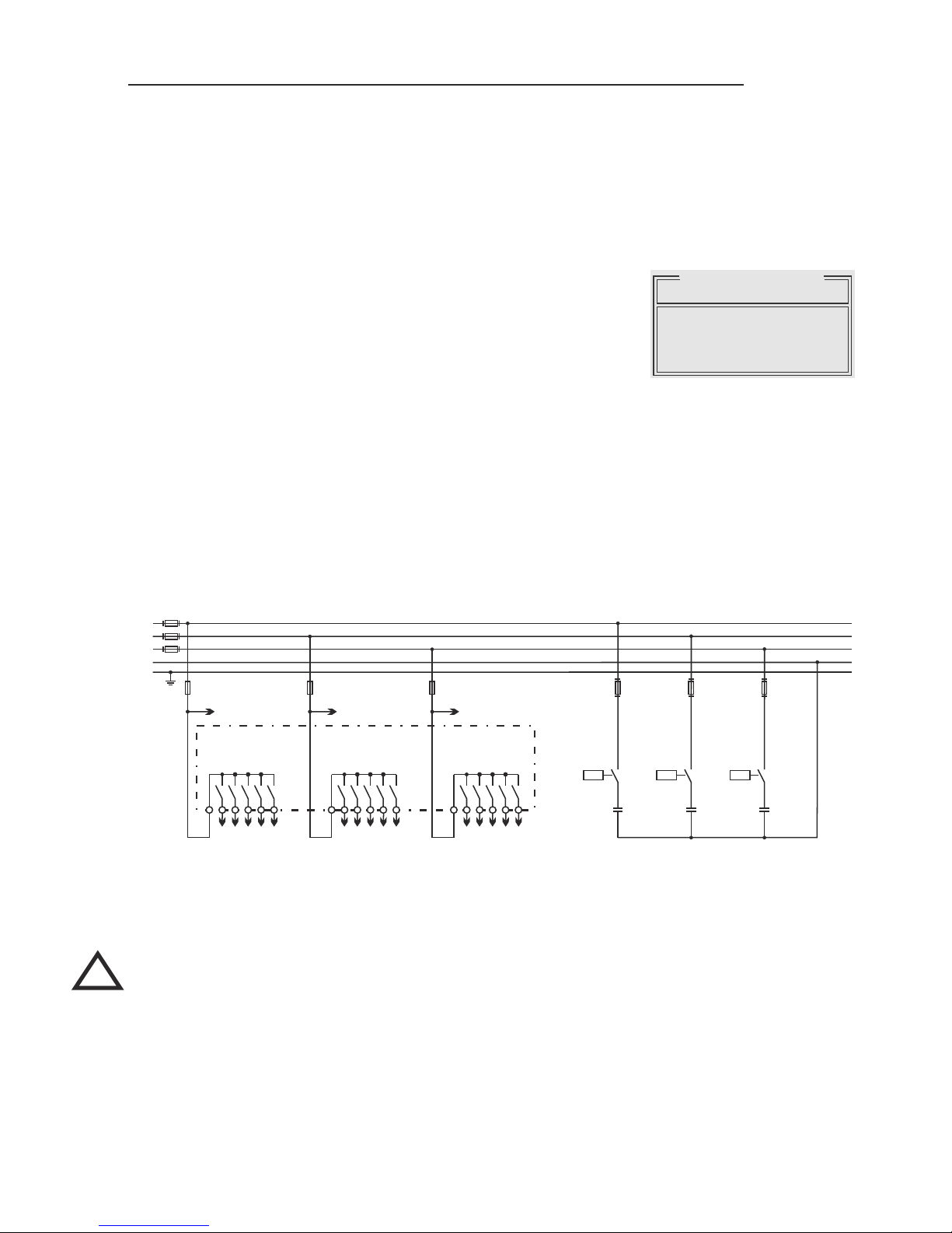
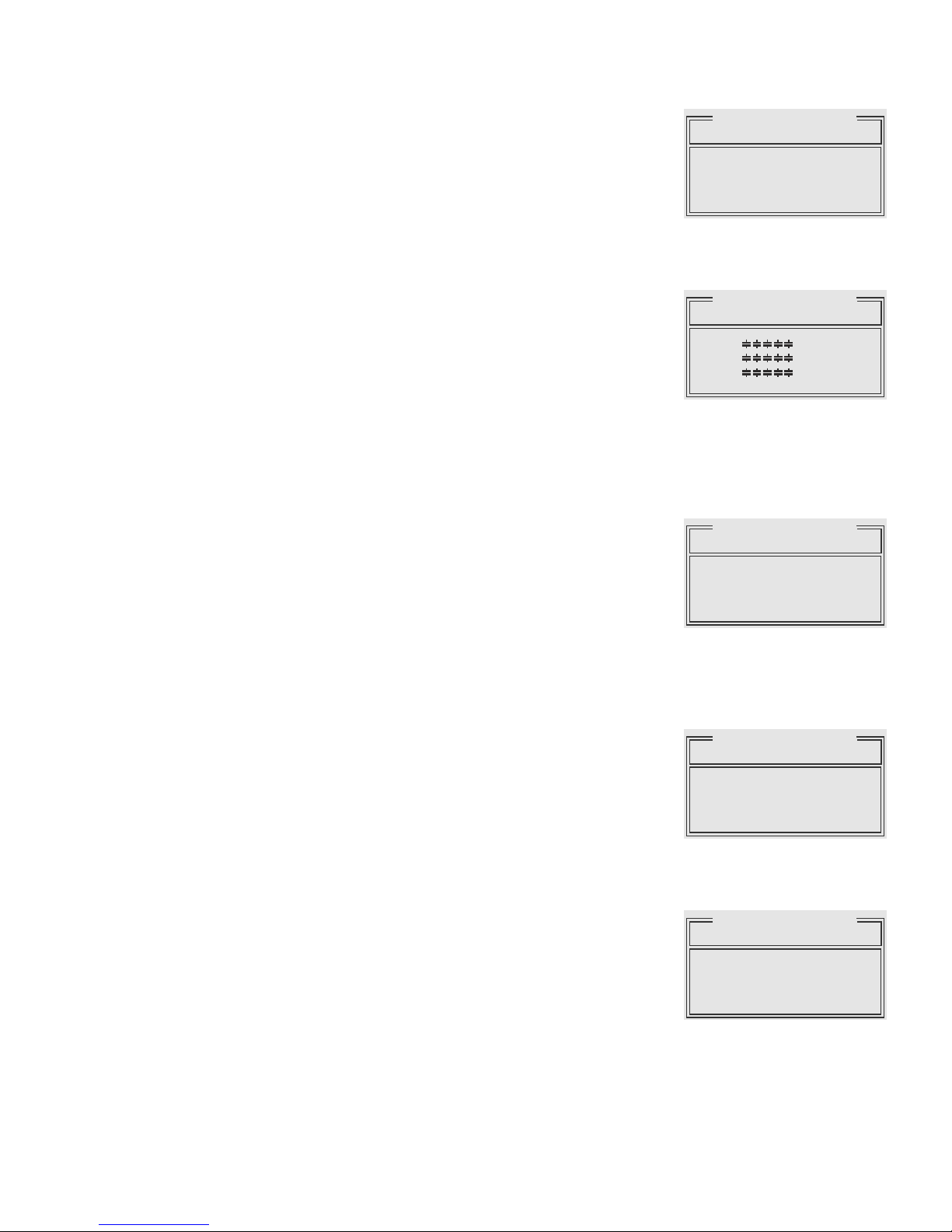
Example :
3x 5 single-phase capacitors (L-N)
Output assignment
L1 (R)
L2 (S)
L3 (T)
P1 1 2 3 4 5 P2 6 7 8 9 10 P3 11 12 13 14 15
Output 1-5 Output 6-10 Output 11-15
meas.voltage L1 meas.voltage L2 meas.voltage L3
PE
N
F1: 6,3AT F1: 6,3AT F1: 6,3AT
C1.1 (C1 at L1-N)
C1.2 (C1 at L2-N)
C1.3 (C1 at L3-N)
C2.1 (C2 at L1-N)
C2.2 (C2 at L2-N)
C2.3 (C2 at L3-N)
C3.1 (C3 at L1-N)
C4.1 (C4 at L1-N)
C5.1 (C5 at L1-N)
C3.2 (C3 at L2-N)
C4.2 (C4 at L2-N)
C5.2 (C5 at L2-N)
C3.3 (C3 at L3-N)
C4.3 (C4 at L3-N)
C5.3 (C5 at L3-N)
K1
(K2)
(K3)
(K4)
(K5)
K6
(K7)
(K8)
(K9)
(K10)
K11
(K12)
(K13)
(K14)
(K15)
C1.1
(C2.1)
(C3.1)
(C4.1)
(C5.1)
C1.2
(C2.2)
(C3.2)
(C4.2)
(C5.2)
C1.3
(C2.3)
(C3.3)
(C4.3)
(C5.3)
PROGRAM-MODE
1 LANGUAGE [1]
[ ENGLISH ]
=== PROGRAM-MODE ===
CONTROL-MODE [2]: MIXED-MODE 3-phasige measuring
3 current transformers required. Values displayed and calculated per phase. Connection of
measuring current and measuring voltage see page 6.
Controlling done with max. 4 outputs per phase for switching of single phase capacitors L-N.
The rest of the outputs (min. 3, max. 12) are used for switching of three-phase capacitors
to control the base load.
Partitioning into single-phase / three-phase capacitors is done at
Programming: 4 ENDSTOP!
The allocation of the switching outputs to the particular capacitors can be retrieved in AUTOMODE on HELP-pages 7…9.
CONTROL-MODE [3]:
3-phase measuring / max. 3x5 single-phase capacitores L-L
3 current transformers required. Values displayed and calculated per phase.
Controlling done with max. 5 outputs per phase, switching of single phase capacitors L-L
L1 (R)
L2 (S)
L3 (T)
Example:
3x 4 single-phase-capacitors +
3 standard 3-phase capacitors
Output assignment
3 x 4 Single-phase steps
3 Three-phase-
capacitors
P1 1 2 3 4 5 P2 6 7 8 9 10 P3 11 12 13 14 15
Output 1-5 Output 6-10 Output 11-15
meas.voltage L1 meas.voltage L2 meas.voltage L3
PE
N
K 5
(K10)
(K15)
F1: 6,3AT F1: 6,3AT F1: 6,3AT
C1.1 (C1 at L1-N)
C1.2 (C1 at L2-N)
C1.3 (C1 at L3-N)
C2.1 (C2 at L1-N)
C2.2 (C2 at L2-N)
C2.3 (C2 at L3-N)
C3.1 (C3 at L1-N)
C4.1 (C4 at L1-N)
C3.2 (C3 at L2-N)
C4.2 (C4 at L2-N)
C3.3 (C3 at L3-N)
C4.3 (C4 at L3-N)
C1Σ (C1 3-phas.)
C2Σ (C2 3-phas.)
C3Σ (C3 3-phas.)
C1Σ
( C2Σ )
( C3Σ )
K1
(K2)
(K3)
(K4)
K6
(K7)
(K8)
(K9)
K11
(K12)
(K13)
(K14)
C1.1
(C2.1)
(C3.1)
(C4.1)
C1.2
(C2.2)
(C3.2)
(C4.2)
C1.3
(C2.3)
(C3.3)
(C4.3)
L1 (R)
L2 (S)
L3 (T)
Example:
3x 5 single-phase capacitors (L-L)
Output assignment
P1 1 2 3 4 5 P2 6 7 8 9 10 P3 11 12 13 14 15
Output 1-5 Output 6-10 Output 11-15
meas.voltage L1 meas.voltage L2 meas.voltage L3
PE
N
F1: 6,3AT F1: 6,3AT F1: 6,3AT
C1.1 (C1 at L1-L2)
C1.2 (C1 at L2-L3)
C1.3 (C1 at L3-L1)
C2.1 (C2 at L1-L2)
C2.2 (C2 at L2-L3)
C2.3 (C2 at L3-L1)
C3.1 (C3 at L1-L2)
C4.1 (C4 at L1-L2)
C5.1 (C5 at L1-L2)
C3.2 (C3 at L2-L3)
C4.2 (C4 at L2-L3)
C5.2 (C5 at L2-L3)
C3.3 (C3 at L3-L1)
C4.3 (C4 at L3-L1)
C5.3 (C5 at L3-L1)
K1
(K2)
(K3)
(K4)
(K5)
K6
(K7)
(K8)
(K9)
(K10)
K11
(K12)
(K13)
(K14)
(K15)
C1.1
(C2.1)
(C3.1)
(C4.1)
(C5.1)
C1.2
(C2.2)
(C3.2)
(C4.2)
(C5.2)
C1.3
(C2.3)
(C3.3)
(C4.3)
(C5.3)
=== PROGRAMM-MODE ===
CONTROL-MODE [4]:
3-phase measuring / max. 15 three-phase capacitors
3 current transformers required. Connection of measuring current and measuring voltage
refer to page 6.
Values displayed and calculated per phase.
Controlling done with max. 15 outputs according to maximum or mean-value of the reactive
power
CONTROL-MODE [5]:
1-phase measuring / max. 15 three-phase capacitors
Only 2 current transformer in L1 required
Connection of measuring current and measuring voltage see page 6
Values extrapolated to all phases (balance assumed)
Measuring complies with conventional measuring for switching of three-phase capacitors.
CONTROL-MODE [6]:
1-phase measuring / max. 15 three-phase capacitors
with capacitor current measurement
According variant 5, but the free current inputs (L2 or L3) are used for capacitor current
measurement for real monitoring of capacitors.
Connection of measuring current and measuring voltage see page 6!
- 13 -
L1 (R)
L2 (S)
L3 (T)
Example:
15 standard 3-phase capacitors
P1 1 2 3 4 5 P2 6 7 8 9 10 P3 11 12 13 14 15
Output 1-5 Output 6-10 Output 11-15
meas.voltage L1 meas.voltage L2 meas.voltage L3
PE
N
K1 K2 K15
F1: 6,3AT F1: 6,3AT F1: 6,3AT
C1 ( 3-phase)
C6 ( 3-phase)
C11 ( 3-phase)
C2 ( 3-phase)
C7 ( 3-phase)
C12 ( 3-phase)
C3 ( 3-phase)
C8 ( 3-phase)
C13 ( 3-phase)
C4 ( 3-phase)
C9 ( 3-phase)
C14 ( 3-phase)
C5 ( 3-phase)
C10 ( 3-phase)
C15 ( 3-phase)
C1 C2 C15
....
=== PROGRAMM-MODE ===
3 I-CONVERTER PRIM [1000 ] A / X ( 5 ... 13000) A
Selects the primary current of the current converter.
Sequential adjustment of L1...L3.
via the é / ê keys. Save and continue with ENTER
4 I-CONVERTER SEC 1000 A /[ 5 ]A ( 1 / 5 A )
This sets the secondary current of the current converter.
Selection via é / ê. Save and continue with ENTER
5 END STOPP
Programming of the maximum number of active
capacitor branches.
Depending on the selected operation mode the
maximum number of connected capacitors at the output
groups L1…L3 and (if available) for the output groups Σ
(three-phase capacitors) are set.
The visible symbols of the capacitors correspond to the
connected outputs.
Input via é / ê. Save and continue with ENTER
6 CONTROL SERIES [1] ( 1...20 + ED )
The ratio of the capacitor branch powers determines the
control series, the power of the first capacitor always
being assigned the value 1.
Selection of desired control series consecutively for
L1…L3 and for Σ (three-phase outputs).
If the required control series should not be present, the
user may define a special one in control series “ED” ( see
Annex 4: Control-series editor )
7 CONTROL PRINCIPLE
The control preference may be selected here:
SEQUENTIAL connection
LOOP connection
INTELLIGENT loop connection (default setting)
COMBINED CHOKE
See Section 13 for an explanation of the control modes.
Selection with é / ê keys.
Save and continue with ENTER
8 POWER 1st STAGE [0.01 ... 255.99] / [10...2550] kvar
To determine the controller's response sensitivity, the
dimensions of the smallest capacitor (stage 1) must be
known. They are entered in two steps in kvar. The
integral kvar values (before the comma) are initially
selected via the é / ê keys and saved with ENTER.
The positions after the comma are then selected, again
via the é / ê keys.
If the capacitor value is below the response sensitivity, a
warning will occur ( indication of “!” in the display )
- 14 -
PROGRAM-MODE
7 CONTR.PRINC. 3]
[ INTELLIGENT ]
PROGRAM-MODE
3 I-CONVERTER PRIM
[ 1000]A / 5 A
1000]A / 5 A
1000]A / 5 A
L1
L2
L3
PROGRAM-MODE
8 POWER 1.STAGE
[ 25].00 kvar
25 .00 kvar
25 .00 kvar
L1-N
L2-N
L3-N
PROGRAM-MODE
6 CONT.SERIES L1-N
12333
12333
12333
[ 3]
3
3
L1-N
L2-N
L3-N
1 2 3 4 5
PROGRAM-MODE
5 END STOP L1-N
[ 5]
5
5
L1-N
L2-N
L3-N
1 2 3 4 5
 Loading...