


Filters for Power Lines
(Low leakage current)
16 to 100 A,
100 dB from 14 kHz
Series/Type: B84263
Date: January 2004
EPCOS AG 2004. Reproduction, publication and dissemination of this data sheet, enclosures hereto and the
information contained thereinwithout EPCOS' prior express consent is prohibited.
Purchase orders are subject to the General Conditions for the Supply of Products and Services of the Electrical
and Electronics Industry recommended by the ZVEI (German Electrical and Electronic Manufacturers' Association), unless otherwise agreed.
Filters for power lines (low leakage current) B84263
16 to 100 A, 100 dB from 14 kHz
2- and 4-line-filters
16 to 100 A
Multi-stage
Stopband attenuation 14 kHz to 40 GHz
Features
Low volume and low voltage drop
Practically no leakage current flow on the grounding conductor in normal operation because of
the capacitor configuration (capacitive circuit to ground only through neutral)
Insertion loss to CISPR 17
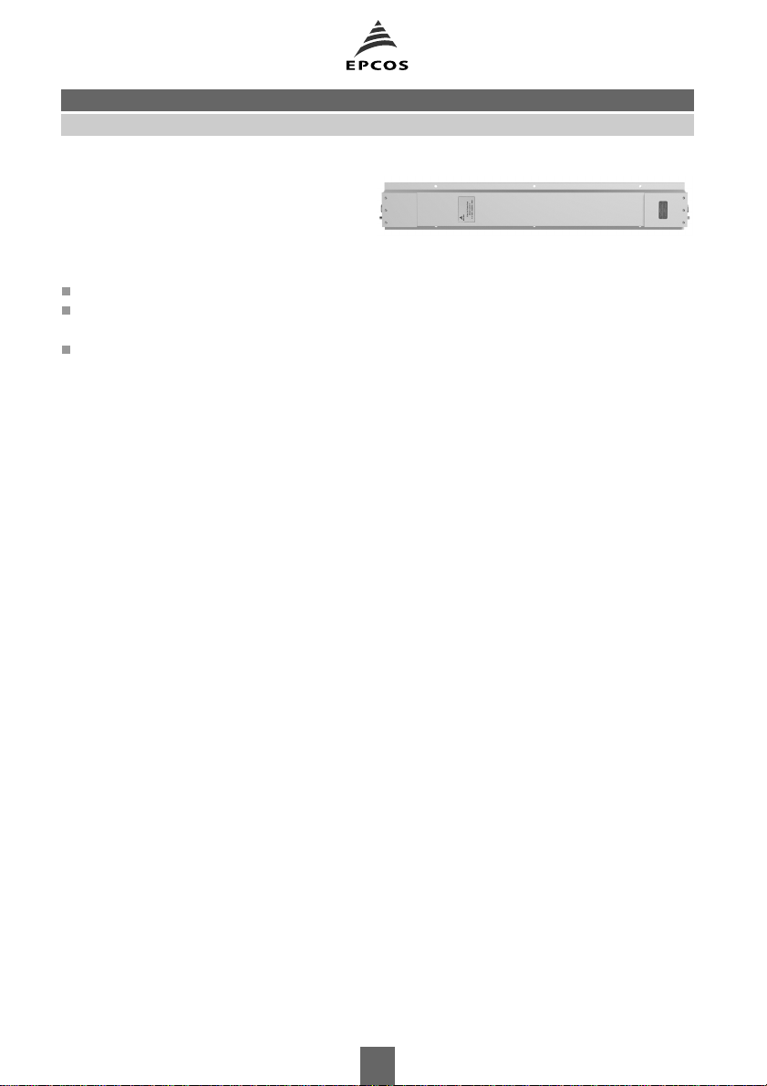
Design
The electrical components are incorporated in an RF-tight case of high-grade steel. The cables
enter through glands. The RF-tight termination of the openings is produced by specially shaped
lids.
The conductors and equipment grounding conductor are connected by threaded bolts. The surface around the fixing holes is left as bare metal (unpainted) to ensure good RF contact with metal surfaces (chassis, ground).
Protective measures (grounding)
The high capacitances between the lines and ground require special protective measures. If there
are no product-specific requirements, protection with a secondary ground wire (cross section min.
10 mm2) in accordance with EN 50178 is necessary. For this purpose the filter case have connecting bolts at each end.
Resistors are incorporated in the filter to discharge capacitors after turn-off.
Scope of supply
Filters are supplied complete with all parts required for RF-tight installation (fixing screws,
flanges, RF gaskets, cable glands) and installation instructions.
Installation
No welding is needed on the shielding wall, so any subsequent installation is quite simple. And
the uniform template of the attachment points allows straightforward replacement of 2-line filters
by 4-line filters for example.
Accessories and special versions
RF-tight flexible connector fittings are available for installation spaced away from the shielding
wall. Filters with an EMP protection add-on for surge currents up to 100 kA per line are available
on request. To match requirements, filters can be supplied with different kinds of EMC or shielding cable glands.
Tests
All filters are 100% tested and the results are archived under a filter's serial number. If required, a
test report can be generated for the serial number.
2
Filters for power lines (low leakage current) B84263
16 to 100 A, 100 dB from 14 kHz
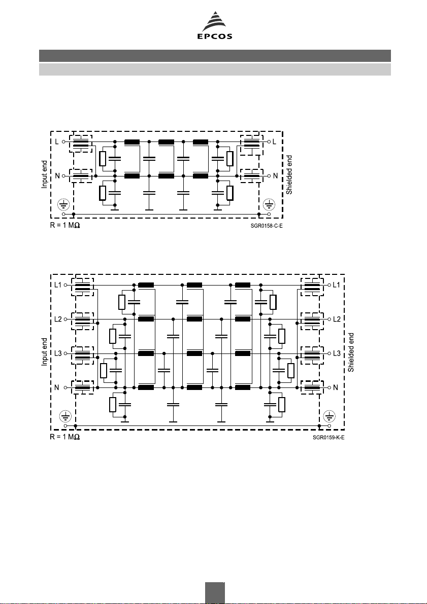
Circuit diagrams
2-line filters
4-line filters
3
Filters for power lines (low leakage current) B84263
16 to 100 A, 100 dB from 14 kHz
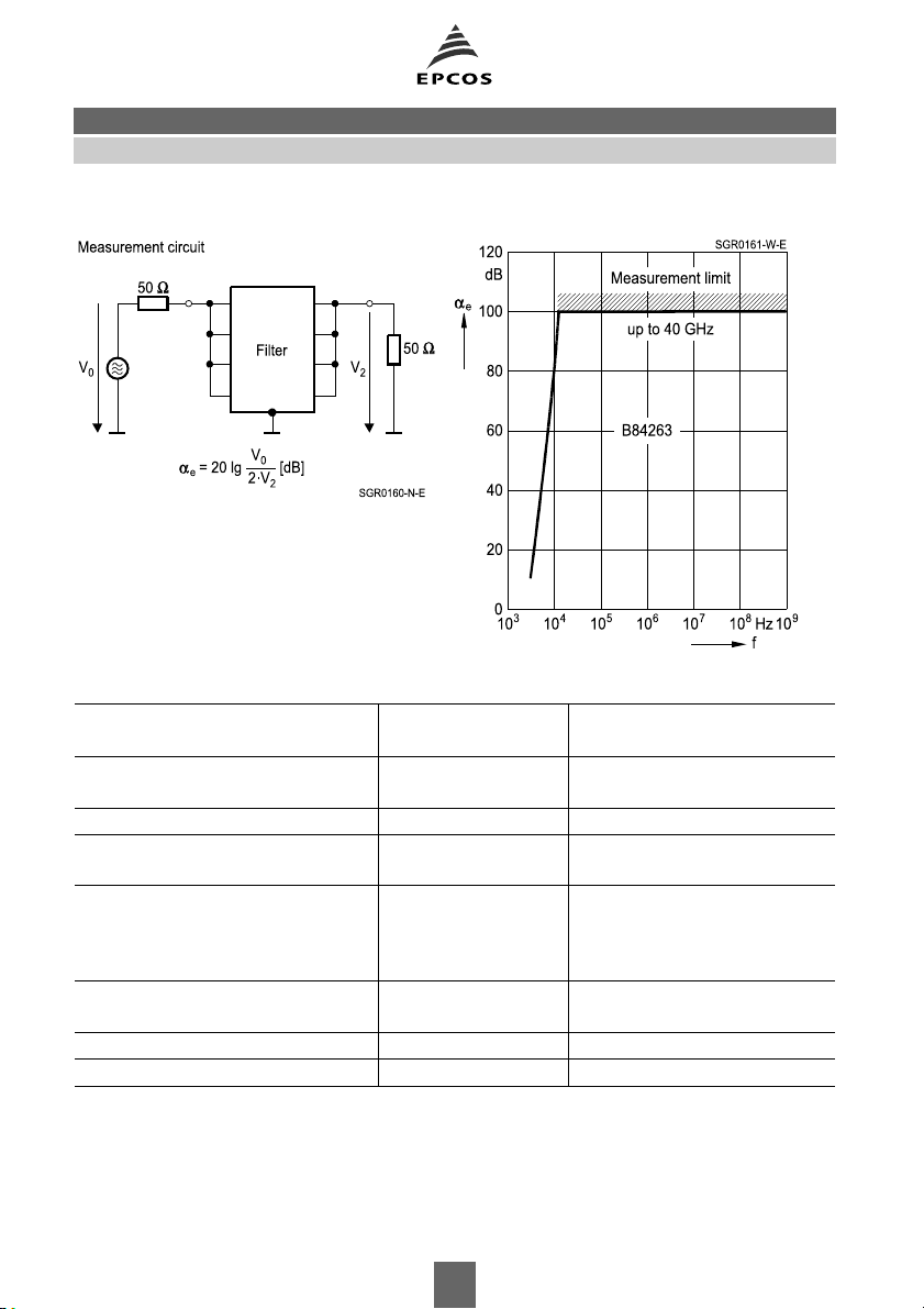
Insertion loss αe(typical values at Z = 50 Ω)
Asymmetrical measurement circuit
to MIL-STD-220A
General technical data
Rated voltage VR250 V Line/line
2-line filters Line/case
Rated voltage VR440 V Line/line
4-line filters 250 V Line/case
Rated frequency f
Rated current I
50/60 Hz
R
See characteristics Referred to +40 °C ambient
R
temperature
Maximum admissible
overcurrent
I
75 IRfor 50 ms
over
10 IRfor 1 s
2 IRfor 1 min
1.4 IRfor 15 min
Test voltage V
1200 VDC, 2 s Line/line
test
1200 VDC, 2 s Line/case
Voltage drop/phase ∆V <1 % Of VRat 50 Hz and I
Maximum DC resistance R
See characteristics Per line
max
R
4
Filters for power lines (low leakage current) B84263
16 to 100 A, 100 dB from 14 kHz
General technical data (continued)
Power dissipation PDSee characteristics At rated current I
Capacitive leakage current I
See characteristics Difference potential N to PE at
leak
R
50 Hz
Max. permissible harmonic
8 % To EN 50160
distortion (THD)
Permissible ambient
TA25/+40 °C
temperature
Climatic category
(EN 60068-1)
25/085/56 25 °C/+85 °C/56 days damp
heat test
Mechanical version C Cable glands at both ends or
flexible connector fitting
D Direct connection to shielding
wall
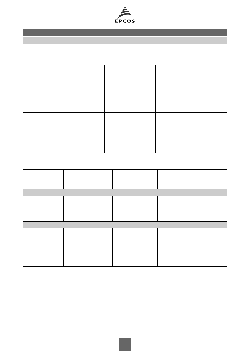
Characteristics and ordering codes
I
R
A
Mechanical
version
R
mΩ
max
P
I
leak
Dimensional
D
drawing
W
mA/V
Page Approx.
weight
kg
Ordering code
2-line filters
16
16
40
40
C
D
C
D
< 40 < 18 < 2 1 6 8
< 40 < 18 < 2 2 7 8
< 20 < 60
< 20 < 60
< 2.5
3 8 18
< 2.5
4 9 18
B84263C0022B013
B84263D0022B013
B84263C0023B013
B84263D0023B013
4-line filters
16
16
40
40
100
100
C
D
C
D
C
D
< 80 < 60 < 2 5 10 25
< 80 < 60 < 2 6 11 25
< 30 < 140
< 30 < 140
< 6 < 70
< 6 < 180
< 2.5
7 12 27
< 2.5
8 13 27
< 2.5
9 14 50
< 2.5
10 15 50
B84263C1160E003
B84263D1160E003
B84263C1400E003
B84263D1400E003
B84263C1101E003
B84263D1101E003
5

Filters for power lines (low leakage current) B84263
16 to 100 A, 100 dB from 14 kHz
Dimensional drawings
Dimensional drawing 1 (cable glands at both ends) 2 x 16 A
B84263C0022B013
➀ Input end: Cable gland PG 21 (mounted)
➁ Shielded end: Cable gland PG 29/21
(cable gland PG 29, PG 21 and reducer ring in accessory bag)
Paint color: RAL 7035 (light gray, semigloss)
Fixing dimensions
The cable glands (with cutout sealing ring) are suitable for the following overall cable diameter:
PG 29 17 to 19 mm 20 to 22 mm 23 to 25 mm 26 to 28 mm
PG 21 9 to 11 mm 12 to 14 mm 15 to 17 mm 18 to 20 mm
RF-tight connection to shielding wall with connector fitting, see page 16.
6

Filters for power lines (low leakage current) B84263
16 to 100 A, 100 dB from 14 kHz
Dimensional drawing 2 (direct connection to shielding wall) 2 x 16 A
B84263D0022B013
➀ Input end: Cable gland PG 21 (mounted)
➁ Shielded end: Cable gland PG 29/21
(cable gland PG 29, PG 21 and reducer ring in accessory bag)
Paint color: RAL 7035 (light gray, semigloss)
Fixing dimensions
The cable glands (with cutout sealing ring) are suitable for the following overall cable diameter:
PG 29 17 to 19 mm 20 to 22 mm 23 to 25 mm 26 to 28 mm
PG 21 9 to 11 mm 12 to 14 mm 15 to 17 mm 18 to 20 mm
RF-tight connection to shielding wall, see page 16.
7

Filters for power lines (low leakage current) B84263
16 to 100 A, 100 dB from 14 kHz
Dimensional drawing 3 (cable glands at both ends) 2 x 40 A
B84263C0023B013
➀ Input end: Cable gland PG 21 (mounted)
➁ Shielded end: Cable gland PG 29/21
(cable gland PG 29, PG 21 and reducer ring in accessory bag)
Paint color: RAL 7035 (light gray, semigloss)
Fixing dimensions
The cable glands (with cutout sealing ring) are suitable for the following overall cable diameter:
PG 29 17 to 19 mm 20 to 22 mm 23 to 25 mm 26 to 28 mm
PG 21 9 to 11 mm 12 to 14 mm 15 to 17 mm 18 to 20 mm
RF-tight connection to shielding wall with connector fitting, see page 16.
8

Filters for power lines (low leakage current) B84263
16 to 100 A, 100 dB from 14 kHz
Dimensional drawing 4 (direct connection to shielding wall) 2 x 40 A
B84263D0023B013
➀ Input end: Cable gland PG 21 (mounted)
➁ Shielded end: Cable gland PG 29/21
(cable gland PG 29, PG 21 and reducer ring in accessory bag)
Paint color: RAL 7035 (light gray, semigloss)
Fixing dimensions
The cable glands (with cutout sealing ring) are suitable for the following overall cable diameter:
PG 29 17 to 19 mm 20 to 22 mm 23 to 25 mm 26 to 28 mm
PG 21 9 to 11 mm 12 to 14 mm 15 to 17 mm 18 to 20 mm
RF-tight connection to shielding wall, see page 16.
9

Filters for power lines (low leakage current) B84263
16 to 100 A, 100 dB from 14 kHz
Dimensional drawing 5 (cable glands at both ends) 4 x 16 A
B84263C1160E003
➀ Input end: Cable gland PG 29/21
(PG 29 mounted, PG 21 and reducer ring in accessory bag)
➁ Shielded end: Cable gland PG 29/21
(cable gland PG 29, PG 21 and reducer ring in accessory bag)
Paint color: RAL 7035 (light gray, semigloss)
Fixing dimensions
The cable glands (with cutout sealing ring) are suitable for the following overall cable diameter:
PG 29 17 to 19 mm 20 to 22 mm 23 to 25 mm 26 to 28 mm
PG 21 9 to 11 mm 12 to 14 mm 15 to 17 mm 18 to 20 mm
RF-tight connection to shielding wall with connector fitting, see page 16.
10

Filters for power lines (low leakage current) B84263
16 to 100 A, 100 dB from 14 kHz
Dimensional drawing 6 (direct connection to shielding wall) 4 x 16 A
B84263D1160E003
➀ Input end: Cable gland PG 29/21
(PG 29 mounted, PG 21 and reducer ring in accessory bag)
➁ Shielded end: Cable gland PG 29/21
(cable gland PG 29, PG 21 and reducer ring in accessory bag)
Paint color: RAL 7035 (light gray, semigloss)
Fixing dimensions
The cable glands (with cutout sealing ring) are suitable for the following overall cable diameter:
PG 29 17 to 19 mm 20 to 22 mm 23 to 25 mm 26 to 28 mm
PG 21 9 to 11 mm 12 to 14 mm 15 to 17 mm 18 to 20 mm
RF-tight connection to shielding wall, see page 16.
11

Filters for power lines (low leakage current) B84263
16 to 100 A, 100 dB from 14 kHz
Dimensional drawing 7 (cable glands at both ends) 4 x 40 A
B84263C1400E003
➀ Input end: Cable gland PG 29/21
(PG 29 mounted, PG 21 and reducer ring in accessory bag)
➁ Shielded end: Cable gland PG 29/21
(cable gland PG 29, PG 21 and reducer ring in accessory bag)
Paint color: RAL 7035 (light gray, semigloss)
Fixing dimensions
The cable glands (with cutout sealing ring) are suitable for the following overall cable diameter:
PG 29 17 to 19 mm 20 to 22 mm 23 to 25 mm 26 to 28 mm
PG 21 9 to 11 mm 12 to 14 mm 15 to 17 mm 18 to 20 mm
RF-tight connection to shielding wall with connector fitting, see page 16.
12

Filters for power lines (low leakage current) B84263
16 to 100 A, 100 dB from 14 kHz
Dimensional drawing 8 (direct connection to shielding wall) 4 x 40 A
B84263D1400E003
➀ Input end: Cable gland PG 29/21
(PG 29 mounted, PG 21 and reducer ring in accessory bag)
➁ Shielded end: Cable gland PG 29/21
(cable gland PG 29, PG 21 and reducer ring in accessory bag)
Paint color: RAL 7035 (light gray, semigloss)
Fixing dimensions
The cable glands (with cutout sealing ring) are suitable for the following overall cable diameter:
PG 29 17 to 19 mm 20 to 22 mm 23 to 25 mm 26 to 28 mm
PG 21 9 to 11 mm 12 to 14 mm 15 to 17 mm 18 to 20 mm
RF-tight connection to shielding wall, see page 16.
13

Filters for power lines (low leakage current) B84263
16 to 100 A, 100 dB from 14 kHz
Dimensional drawing 9 (cable glands at both ends) 4 x 100 A
B84263C1101E003
➀ Input end: Cable gland PG 42/29
(PG 42 mounted, PG 29 and reducer ring in accessory bag)
➁ Shielded end: Cable gland PG 42/29
(cable gland PG 42, PG 29 and reducer ring in accessory bag)
Paint color: RAL 7035 (light gray, semigloss)
Fixing dimensions
The cable glands (with cutout sealing ring) are suitable for the following overall cable diameter:
PG 42 29 to 31 mm 32 to 34 mm 35 to 37 mm 38 to 40 mm
PG 29 17 to 19 mm 20 to 22 mm 23 to 25 mm 26 to 28 mm
RF-tight connection to shielding wall with connector fitting, see page 16.
14

Filters for power lines (low leakage current) B84263
16 to 100 A, 100 dB from 14 kHz
Dimensional drawing 10 (direct connection to shielding wall) 4 x 100 A
B84263D1101E003
➀ Input end: Cable gland PG 42/29
(PG 42 mounted, PG 29 and reducer ring in accessory bag)
➁ Shielded end: Cable gland PG 42/29
(cable gland PG 42, PG 29 and reducer ring in accessory bag)
Paint color: RAL 7035 (light gray, semigloss)
Fixing dimensions
The cable glands (with cutout sealing ring) are suitable for the following overall cable diameter:
PG 42 29 to 31 mm 32 to 34 mm 35 to 37 mm 38 to 40 mm
PG 29 17 to 19 mm 20 to 22 mm 23 to 25 mm 26 to 28 mm
RF-tight connection to shielding wall, see page 16.
15

Filters for power lines (low leakage current) B84263
16 to 100 A, 100 dB from 14 kHz
RF-tight connection to shielding wall with connector fitting (mechanical version C)
Cable
gland
PG 29 Nominal width 25 mm B84298A0042L*** ∅ 37 +0.5 mm ∅55 +5 mm
PG 42 Nominal width 40 mm B84298A0044L*** ∅ 54 +0.5 mm ∅70 +5 mm
(***: add required length in cm (see also chapter "Installation accessories").
RF-tight connection to shielding wall (mechanical version D)
Cable
gland
PG 21 Suitable cable gland with ∅ 37 +0.5 mm ∅ 55 +5 mm
PG 29
PG 42
Connector fitting (must
be ordered separately)
Parts for RF-tight mounting (in accessory bag) Required hole in
long thread, RF gasket
and check nut.
Ordering code Hole in shielding
wall
shielding wall
∅ 54 +0.5 mm ∅ 70 +5 mm
Bare metal area
on shielding wall
Bare metal area
on shielding wall
16
 Loading...