

Epcos B 84143 – V xx – R 27 Service Manual
www.DataSheet4U.com
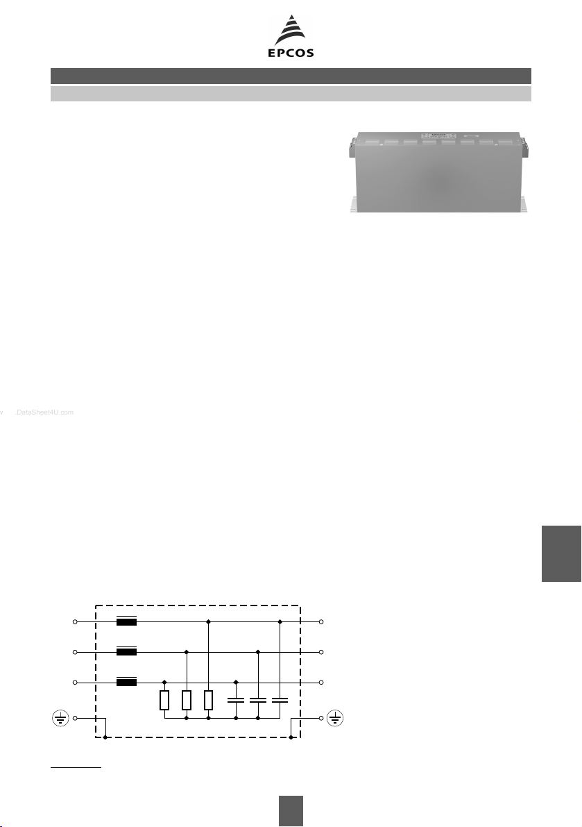
3-Line Filters B84143-V*-R27
Sine-Wave Output Filters
Sine-wave filters for three-phase systems
Rated voltage 440/250 V~, 50/60 Hz
Rated current 6 to 35 A
Construction
■ Three-line filter
■ Metal case
Features
■ Easy to install
■ Space-saving design
■ Degree of protection: IP 20
■ Motor cables of more than 100 m possible
■ Minimized motor noise and eddy
1)
current losses in the motor windings
Applications
■ Sine-wave output filters for frequency converters in
variable speed drivers, solar systems, UPS
Terminals
■ Safe-to-touch terminal blocks
Marking
Marking on component:
Manufacturer’s logo, ordering code, rated voltage,
rated current, rated temperature,
date code
Minimum marking on packaging:
Manufacturer’s logo, ordering code
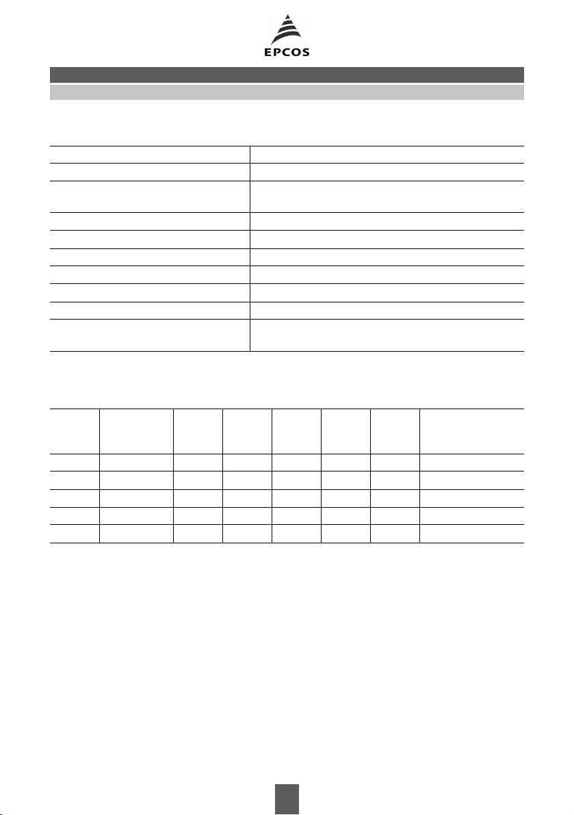
Typical circuit diagram
Inverter LOAD
Wechselrichter Last
U1
V1
W1
1) In accordance with IEC 60529:1989; EN 60529:1991; DIN VDE 0470-1
U2
V2
W2
SSB1572-D
269 03/01
3-Line Filters B84143-V*-R27
Sine-Wave Output Filters
Technical data
Rated voltage V
Rated current I
Test voltage V
R
R
P
440/250 V~, 50/60 Hz
referred to 40 °C ambient temperature
1770 V–, 2 s (line/line)
2700 V–, 2 s (lines/case)
Overload capability 1,5 · I
Converter output frequency f
Converter pulse frequency f
Voltage drop (input to output)
Power dissipation P
V
Capacitive reactive current I
M
P
∆V at I
q
Climatic category 25/1005/21 (– 25
for 1 min per hour
R
0 … 100 Hz
6 … 16 kHz
, 50 Hz
R
typical value
at 230 V, 50 Hz (typical value)
°C/+ 100 °C/21 days damp heat test)
in accordance with EN 60068-1
Characteristics and ordering codes
I
R
Terminal
cross section
2
A
mm
I
q
∆V
P
V
R
Approx.
typ
weight
A
V
W
mΩ
kg
Ordering code
6 4 0,24 10 29 200 5,2 B84143-V6-R27
12 4 0,48 8 37 66 7,9 B84143-V12-R27
16 4 0,81 8 49 49 8,3 B84143-V16-R27
25 6 1,20 7 65 27 11,1 B84143-V25-R27
35 6 1,60 7 70 15 16,6 B84143-V35-R27
270 03/01
 Loading...