

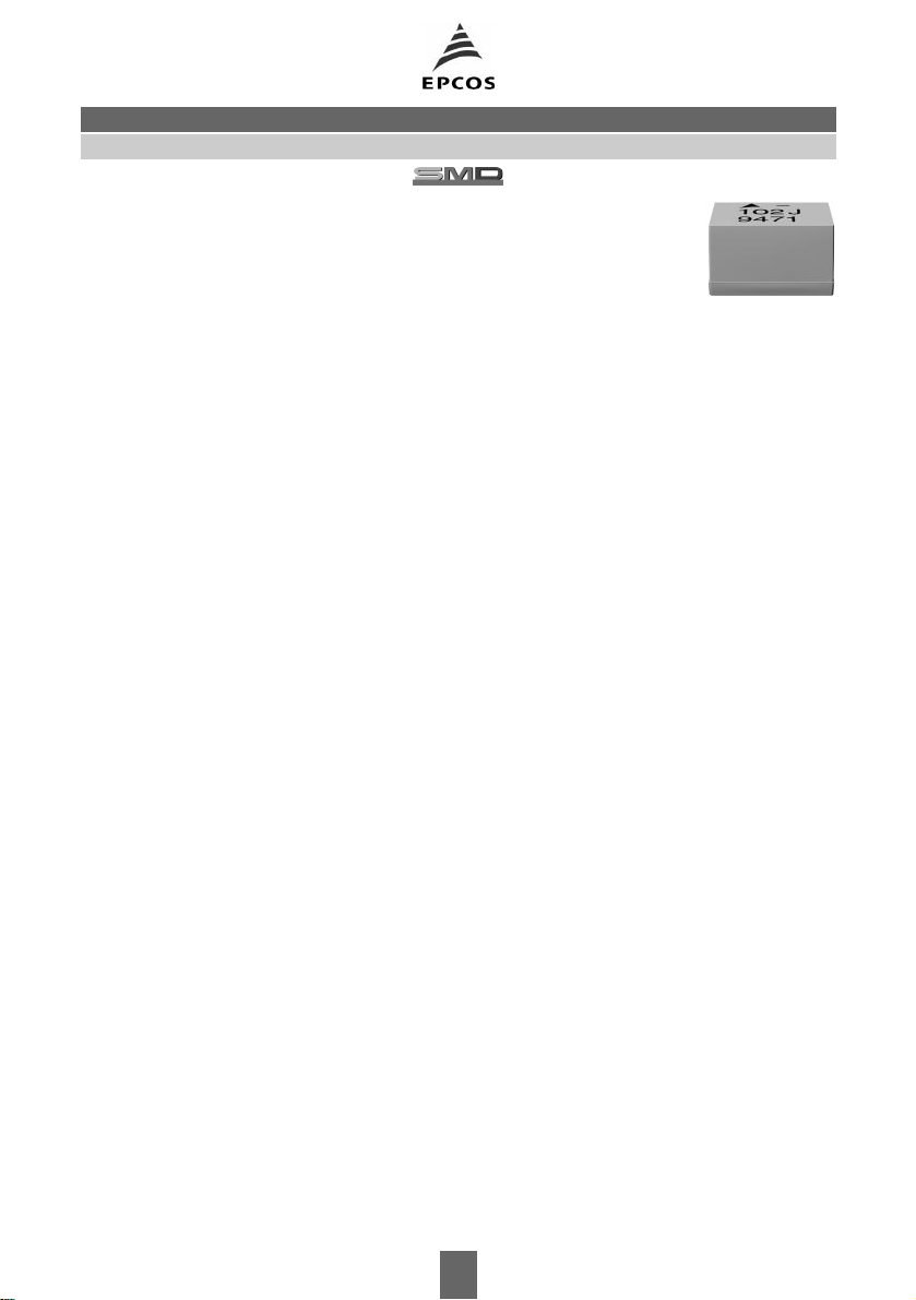
SIMID 1210-A
Size 1210 (EIA) or 3225 (IEC)
Rated inductance 0,0082 to 100 µH
Rated current 65 to 700 mA
Construction
■ Ceramic or ferrite core
■ US-welded winding
■ Flame-retardant encapsulation
Features
■ High
Q
factor
■ High resonance frequency
■ Suitable for reflow (IR and vapor phase)
and wave soldering
Applications
■ Filtering of supply voltages, coupling, decoupling
■ Antenna systems
■ Automotive electronics
■ Telecommunications
Terminals
■ Silver-plated
■ 1–2 µm Cu, 4–6 µm Ag
■ Base material CuSn6
■ Suitable for soldering and conductive adhesion
■ No leaching during wave soldering
B82422-ASMT Inductors, SIMID Series
Marking
Marking on component:
Manufacturer and series mark »–«
L
value (in nH) and tolerance ofL value (coded),
date of manufacture (coded)
Minimum data on reel:
Manufacturer, part number, ordering code,
L
value and tolerance ofL value,
quantity, date of packing
Delivery mode
8-mm blister tape, wound on 180-mm or 330-mm ∅ reel
For details on taping, packing and packing units see page 153
93 04/00
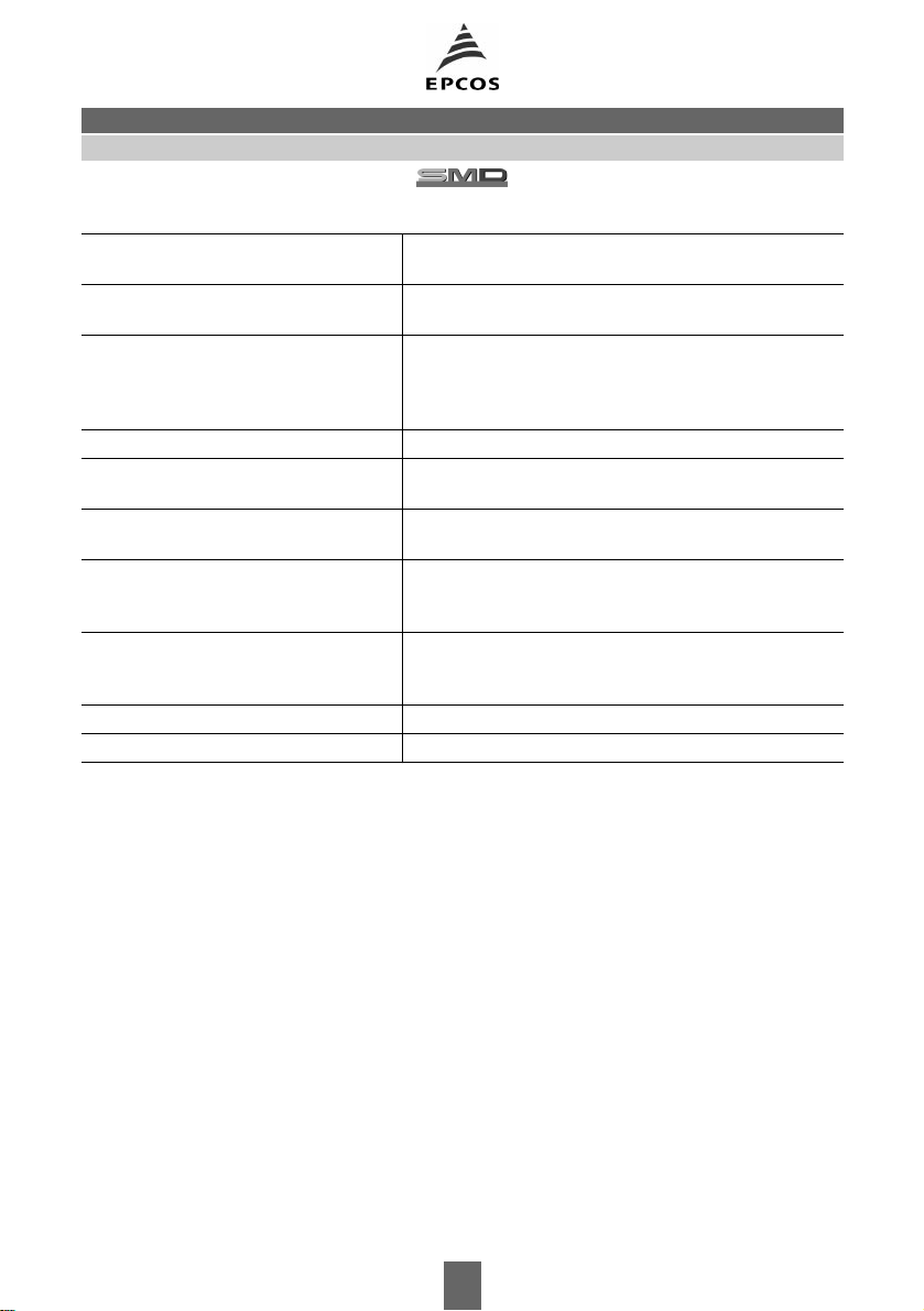
SIMID 1210-A
General technical data
B82422-ASMT Inductors, SIMID Series
Rated inductance
Q factor
Q
min
L
R
Measured with impedance analyzer HP 4194A
at frequency
f
L
Measured with impedance analyzer
HP 4194A/HP 4291A at frequency
Rated current
I
R
Maximum permissible dc with
inductance decrease ∆L/
L
0
≤ 10 %
and temperature increase of ≤ 20 K
at rated temperature of 85°C
Self-resonance frequency
DC resistance
R
max
f
res, min
Measured with network analyzer HP 8753
Measured at 20°C ambient temperature,
measuring current <
I
R
Climatic category In accordance with IEC 60068-1
55/125/56 (– 55°C/+ 125°C/56 days damp heat test)
Solderability In accordance with IEC 60062-2-58
(215 ± 3)°C, (3 ± 0,3) s
Wetting of soldering area: ≥ 95 %
Resistance to soldering heat In accordance with IEC 60068-2-20
260°C, 10 s
∆L/L≤ ± 3%
Permissible PCB bending 2 mm (100 mm long standard PCB)
Weight Approx. 50 mg
f
Q
94 04/00
 Loading...