

CeraDiode CDS3 Series
SMD type, case size 0603 B72500D***
Data sheet
CeraDiode
Reliable ESD protection of single lines
Description
Due to the ongoing miniaturization, today’s electronic devices are more and more sensitive to
electrostatic discharges (ESD) and overvoltages. Therefore reliable protection components become
absolutely necessary to harden your valuable electronics against the impact of ESD.
CeraDiodes are ceramic semiconductors optimized specifically for high performance in Electro Static
Discharge (ESD) applications. The device has a non-linear voltage/current characteristic that is highly
optimized for effectively suppressing extremely fast voltage transients. The device offers superior
parametric stability over the complete operating range of –40 °C to +85 °C.
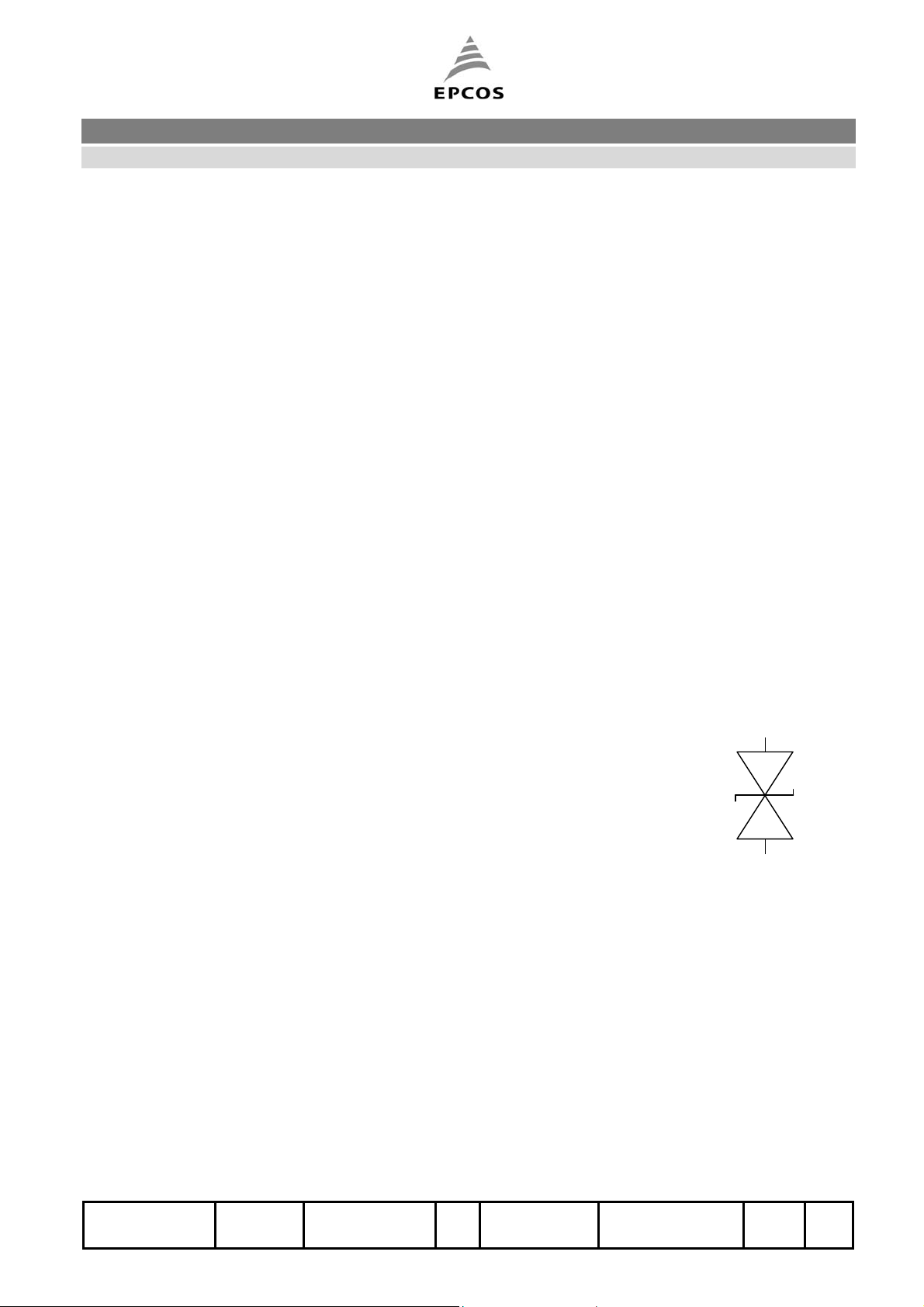
CeraDiodes are bi-directional devices. A single CeraDiode
routes both positive and negative ESD transitions safely to the ground plane. This technique
eliminates the need to route ESD charge into the power plane, possibility damaging nearby integrated
circuits.
connected from signal/dataline to ground
Features
ESD protection according to IEC 61000-4-2 (Level 4)
Endurance specification up to 3000 ESD pulses (IEC 61000-4-2 Level 4)
Suitable for uni- and bidirectional lines
Bidirectional ESD protection in a two-pin device
Routes all ESD events, both positive and negative, safely to ground
Suitable for DC working voltages up to 22 V
No derating of maximum ratings up to 85 °C
Surface mount package in 0603 case size
Extremely fast response time < 0.5 ns
Lead free nickel barrier terminations
Application
Desktop and notebook computers
Peripherals
Portable handheld products (e.g. PDA)
Mobile communication
Consumer products (set top box, MP3 player, digital cameras,...)
Liquid crystal displays (LCD) / monitors
ISSUE DATE 07.10.2004 ISSUE g PUBLISHER KB VS PE PAGE 1/8
CeraDiode CDS3 Series
SMD type, case size 0603 B72500D***
Data sheet
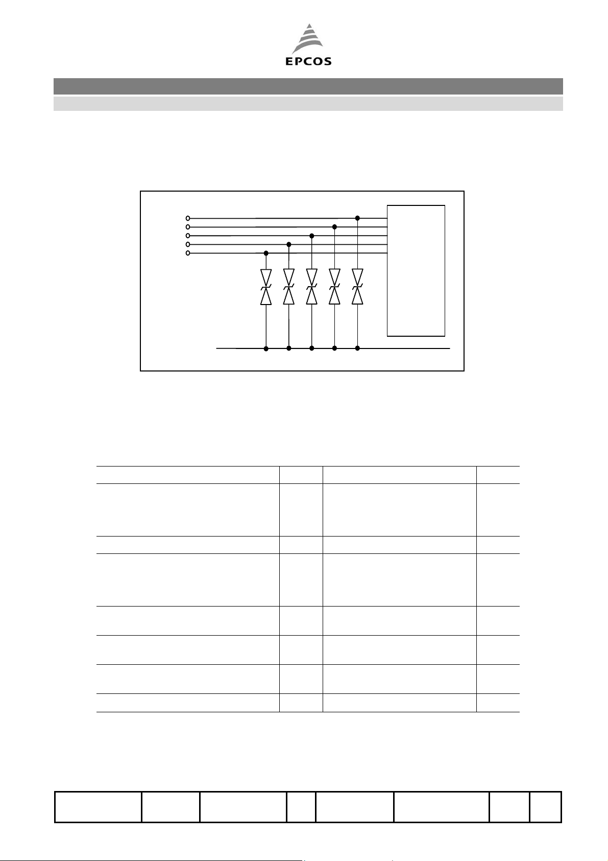
Application example
Protection of I/O Lines with discrete CeraDiodes
I/O
ESD
sensitive
device
CDS
Ground
Maximum ratings (TA = 85 °C)
Rating Symb. Value Unit
Max. DC working voltage VDC CDS3C05GTA: 5.6
Peak current @ 8/ 20 µs I
Peak pulse power @ 8/ 20 µs PPP CDS3C05GTA: 1000
Air discharge ESD capability
(according to IEC 61000-4-2 method)
Contact discharge ESD capability
(according to IEC 61000-4-2 method)
Operating temperature
(without derating)
Storage temperature T
V
CDS3C09GTA: 9.0
CDS3C15GTA: 16.0
CDS3C20GTA: 22.0
30 A
peak
W
CDS3C09GTA: 1600
CDS3C15GTA: 2000
CDS3C20GTA: 2200
V
15 kV
ESD
V
8 kV
ESD
Tj
stg
−40 to +85
−40 to +125
°C
°C
ISSUE DATE 07.10.2004 ISSUE g PUBLISHER KB VS PE PAGE 2/8

CeraDiode CDS3 Series
SMD type, case size 0603 B72500D***
Data sheet
Characteristics (TA = 25 °C)
CDS3C05GTA
Parameter Symb. Conditions Minimum Typical Maximum Unit
Breakdown voltage VBR I
Leakage current *) I
V
L
Clamping voltage VCL I
Capacitance C V = 1 V, f = 1 MHz - 470 - pF
CDS3C09GTA
Parameter Symb. Conditions Minimum Typical Maximum Unit
Breakdown voltage VBR I
Leakage current *) I
V
L
Clamping voltage VCL I
Capacitance C V = 1 V, f = 1 MHz - 220 - pF
CDS3C15GTA
Parameter Symb. Conditions Minimum Typical Maximum Unit
= 1 mA 6.4 - V
BR
= 3.3 V - - 10 µA
L
= 1 A, 8/20 µs - - 19 V
peak
= 1 mA 10 - - V
BR
= 5.6 V - - 10 µA
L
= 1 A, 8/20 µs - - 30 V
peak
Breakdown voltage VBR I
Leakage current *) I
V
L
Clamping voltage VCL I
= 1 mA 22 - - V
BR
= 9 V - - 10 µA
L
= 1 A, 8/20 µs - - 42 V
peak
Capacitance C V = 1 V, f = 1 MHz - 160 - pF
CDS3C20GTA
Parameter Symb. Conditions Minimum Typical Maximum Unit
Breakdown Voltage VBR I
Leakage Current *) I
V
L
Clamping Voltage VCL I
= 1 mA 25 - - V
BR
= 12 V - - 10 µA
L
= 1 A, 8/20 µs - - 50 V
peak
Capacitance C V = 1 V, f = 1 MHz - 56 - pF
*)
Any lower operating voltage than VL results in a lower leakage current
ISSUE DATE 07.10.2004 ISSUE g PUBLISHER KB VS PE PAGE 3/8

C
A
CeraDiode CDS3 Series
SMD type, case size 0603 B72500D***
Data sheet
Typical characteristics
Max. current, energy and average power dissipation
depending on ambient temperature
%
100
90
80
70
60
50
40
30
20
10
0
-55 70 80 90 100 110 120 130 140 150 °
mbient temperature
ISSUE DATE 07.10.2004 ISSUE g PUBLISHER KB VS PE PAGE 4/8

D
C
CeraDiode CDS3 Series
SMD type, case size 0603 B72500D***
Data sheet
Dimensional drawing
l
b
s
k
Symb. Min. Max. Unit
l 1.45 1.75 mm
b 0.7 0.9 mm
s 0.7 0.9 mm
k 0.1 0.4 mm
Recommended solder pads
A
B
B
Symb. Dim. Unit
A 1.0 mm
A
B 1.0 mm
C 1.0 mm
D 3.0 mm
ISSUE DATE 07.10.2004 ISSUE g PUBLISHER KB VS PE PAGE 5/8

CeraDiode CDS3 Series
SMD type, case size 0603 B72500D***
Data sheet
Recommended soldering profiles
Wave soldering Reflow soldering
As far as possible, the components shall be employed within 12 months. They should be left in their
original packings to avoid soldering problems due to oxidized contacts. Storage temperature: –25 to
45 °C. Relative humidity: <75 % annual average, <95 % on max. 30 days in a year.
The usage of mild, non activated fluxes for soldering is recommended, as well as proper cleaning of
the PCB.
Reel dimensions
Direction of unreeling
W
W
1
2
Package: 8 mm tape
Reel material: plastic
A
13±0,2
+2
_
ø60
0
KKE0058-I-E
Definition Symb. Dim. Tol. Unit
Reel diameter A 180
Reel width
(inside)
Reel width
(outside)
W1 8.4
W2 14.4 max. mm
+0 /−3
+1.5/−0
mm
mm
ISSUE DATE 07.10.2004 ISSUE g PUBLISHER KB VS PE PAGE 6/8

g
CeraDiode CDS3 Series
SMD type, case size 0603 B72500D***
Data sheet
Taping according to IEC 60286-3
P
T
T
1
T
1
T
2
D
0
A
0
0
P
2
E
F
0
B
G
P
1
Direction of unreelin
Tape material: cardboard
Dimensions and tolerances
Definition Symbol Dim. Tolerance
Tape end (trailer)
40 min.
W
Leader
empty cavities
25 min.
empty cavities
300 mm
cover tape
Compartment width A0 0.95 ± 0.2
Compartment length B0 1.8 ± 0.2
Sprocket hole diameter D0 1.5
Sprocket hole pitch P0 4.0
Distance center hole to center
compartment
Pitch of the component
compartments
P
2
P
1
2.0
4.0
+0.1/−0
1)
± 0.1
± 0.05
± 0.1
Tape width W 8.0 ± 0.3
Distance edge to center of hole E 1.75 ± 0.1
Distance center hole to center
compartment
F
3.5
± 0.05
Distance compartment to edge G 0.75 min.
Thickness of cardboard tape T 0.9 max.
Overall thickness T2 1.1 max.
1)
≤ ± 0.2 mm over any 10 pitches
ISSUE DATE 07.10.2004 ISSUE g PUBLISHER KB VS PE PAGE 7/8

CeraDiode CDS3 Series
SMD type, case size 0603 B72500D***
Data sheet
Type designation
CD S 3 C 05 G T A
Cera
Diode
Single
type
Chip size
3 = 0603
Chip
DC working
voltage
Reel size
G = 180 mm
Termination
T = Nickel
Suffi
x
Selection Guide
Part number Ordering code Standard
DC working
voltage
(10 µA max.)
CDS3C05GTA B72500D0050A060 3.3 V
CDS3C09GTA B72500D0090A060 5.6 V
CDS3C15GTA B72500D0150A060 9.0 V
CDS3C20GTA B72500D0200A060 12.0 V
CeraDiodes are not suitable for switching applications or for voltage stabilization, where static power dissipation is required.
CeraDiodes are designed for ESD protection and transient suppression!
EPCOS AG 2004. Reproduction, publication and dissemination of this data sheet, enclosures hereto and the information
contained therein without EPCOS' prior express consent is prohibited.
Purchase orders are subject to the General Conditions for the Supply of Products and Services of the Electrical and
Electronics Industry recommended by the ZVEI (German Electrical and Electronic Manufacturers' Association), unless
otherwise agreed.
Maximum
DC working
voltage
5.6 V 4000 180 mm
9.0 V 4000 180 mm
16.0 V 4000 180 mm
22.0 V 4000 180 mm
Qty per reel Reel size
ISSUE DATE 07.10.2004 ISSUE g PUBLISHER KB VS PE PAGE 8/8
 Loading...