

Page 1

EFD 15/8/5
B66413Core
■ E core with flattened, lower center leg
for especially flat transformer design
■ For DC/DC converters
■ EFD cores are supplied as single units
Magnetic characteristics (per set)
Σl/A = 2,27 mm
–1
le= 34 mm
= 15 mm
A
e
A
= 12,2 mm
min
Ve= 510 mm
2
2
3
Approx. weight 2,8 g/set
Ungapped
Material A
nH
value
L
µ
e
A
nH
L1min
P
V
W/set
N49 600 + 30/– 20 % 1080 330 < 0,11
(50 mT, 500 kHz, 100 °C)
N87 780 + 30/– 20 % 1400 560 < 0,28
(200 mT, 100 kHz, 100 °C)
Gapped
Material A
value
L
µ
e
nH
N87 100
± 10 % 180 0,17 B66413-U100-K187
± 15 % 288 0,08 B66413-U160-L187
160
g
approx. mm
g
4,65±0,15
Ordering code
B66413-G-X149
B66413-G-X187
Ordering code
15±0,4
5,3±0,15
11±0,35
5,5±0,2
0,2±0,1
FEK0417-2
7,5±0,15
2,4±0,1
The A
value in the table applies to a core set comprising one ungapped core (dimension g = 0) and
L
one gapped core (dimension g > 0).
Calculation factors (for formulas, see “E cores: general information”, page 382)
Material Relationship between
air gap – A
value
L
Calculation of saturation current
K1 (25 °C) K2 (25 °C) K3 (25 °C) K4 (25 °C) K3 (100 °C) K4 (100 °C)
N87 29,7 – 0,676 44,2 – 0,796 33,2 – 0,873
Validity range: K1, K2: 0,10 mm < s < 1,00 mm
K3, K4: 30 nH < A
< 280 nH
L
507 08/01
Page 2
EFD 15/8/5
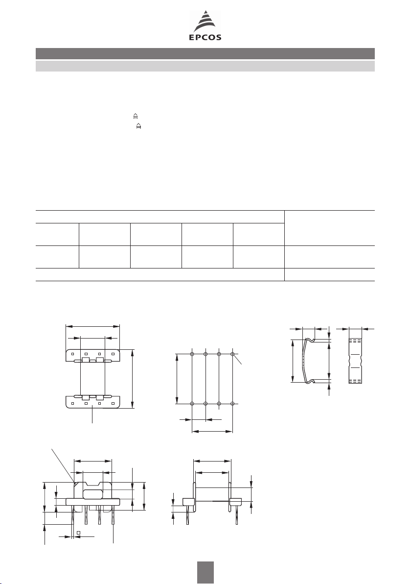
B66414Accessories
Coil former
Material: GFR thermosetting plastic; UL 94 V-0, insulation class to IEC 60085:
B66414-B: F max.operating temperature 155 °C; color code green
B66414-W: H max.operating temperature 180 °C; color code black
Solderability: to IEC 60068-2-20, test Ta, method 1 (aging 3): 235 °C, 2 s
Resistance to soldering heat: to IEC 60068-2-20, test Tb, method 1B: 350 °C, 3,5 s
Winding: see “Processing Notes”, page 157
Squared pins
Yoke
Material: Stainless spring steel (0,25 mm)
Coil former Ordering code
Sections A
mm
N
2
l
N
mm
A
µΩ
value
R
Pins
1 15,5 35,9 79,7 8 B66414-B1008-D1
B66414-W1008-D1
Yoke (ordering code per piece, 2 are required) B66414-B2000
Coil former Yoke
1
8
Duroplast
Marking of pin 1
10,55
5,55+0,15
1,7
8,3 max.3,5±0,2
15±0,2
_
0,1
6,95
2
7
6
_
0,15
0,45
CuSn6, tinned
43
5
16,5±0,2
2,55
0,2
_
7,5
_
13,75
0,151,6
Mounting holes
8
1
3,75
11,25
_
0,2
10,4
8,85 min.
508 08/01
5
ø1+0,1
4
4
FEK0418-A
15,6
4,4
13,6 min. 1
1
4,8 max.
FEK0271-J
Page 3

EFD 15/8/5
SMD coil former with J terminals
Material: GFR liquid crystal polymer (UL 94 V-0, insulation class to IEC 60085:
F max. operating temperature 155 °C), color code black
Solderability: to IEC 60068-2-20, test Ta, method 1 (aging 3): 350 °C, 1 s
Resistance to soldering heat: to IEC 60068-2-20, test Tb, method 1B: 350 °C, 3,5 s
permissible soldering temperature for wire-wrap connection on coil former: 400 °C, 1 s
Winding: see “Processing Notes”, page 160
Yoke
Material: Stainless spring steel (0,25 mm)
Mounting: Preferred assembly direction from the top
Cover plate
For marking and improved processing on assembly machines.
See under coil former for material and resistance to soldering heat.
B66414Accessories
Sections A
mm
N
2
l
N
mm
A
µΩ
value
R
Terminals Ordering code
1 18,1 35,1 66,7 8 B66414-B6008-T1
2 17,1 35,1 70,5 8 B66414-B6008-T2
Yoke (ordering code per piece, 2 are required) B66414-B2000
Cover plate B66414-A7000
Coil former Yoke
_
0,2515
_
0,2
10,4
0,5±0,05
0,5±0,05
_
0,3
20,8
0,6±0,05
0,2
_
6,4
2
3
4
0,55±0,05
Center flange omitted for one-section version
0,2
_
3,45
81
7
6
3,75
11,25
5
10,6 0,2
5,5+0,2
7,7±0,15
16 0,2
Recommended
Empfehlung für das
Leiterplattenlayout
PCB layout
1,2
2,5
17,7
_
_
7,3 0,1
2,6+0,15
_
3,75
11,25
FEK0329-J
4,4
15,6
Cover plate
Abdeckplatte
0,5 max.
12,8±0,1
13,6 min. 1
1
FEK0187-Y
4,8 max.
FEK0271-J
1,8±0,1
6,6±0,1
509 08/01
Page 4

Herausgegeben von EPCOS AG
Marketing Kommunikation, Postfach 80 17 09, 81617 München, DEUTSCHLAND
EPCOS AG 2000. Alle Rechte vorbehalten. Vervielfältigung, Veröffentlichung, Verbreitung und
Verwertung dieser Broschüre und ihres Inhalts ohne ausdrückliche Genehmigung der EPCOS AG
nicht gestattet.
Mit den Angaben in dieser Broschüre werden die Bauelemente spezifiziert, keine Eigenschaften
zugesichert. Bestellungen unterliegen den vom ZVEI empfohlenen Allgemeinen Lieferbedingungen
für Erzeugnisse und Leistungen der Elektroindustrie, soweit nichts anderes vereinbart wird.
Diese Broschüre ersetzt die vorige Ausgabe.
Fragen über Technik, Preise und Liefermöglichkeiten richten Sie bitte an den Ihnen nächstgele-
genen Vertrieb der EPCOS AG oder an unsere Vertriebsgesellschaften im Ausland.
Bauelemente können aufgrund technischer Erfordernisse Gefahrstoffe enthalten. Auskünfte
darüber bitten wir unter Angabe des betreffenden Typs ebenfalls über die zuständige Vertriebsgesellschaft einzuholen.
Published by EPCOS AG
Marketing Communications, P.O. Box 80 17 09, 81617 Munich, GERMANY
EPCOS AG 2000. All Rights Reserved. Reproduction, publication and dissemination of this brochure and the information contained therein without EPCOS’ prior express consent is prohibited.
The information contained in this brochure describes the type of component and shall not be considered as guaranteed characteristics. Purchase orders are subject to the General Conditions for
the Supply of Products and Services of the Electrical and Electronics Industry recommended by the
ZVEI (German Electrical and Electronic Manufacturers’ Association), unless otherwise agreed.
This brochure replaces the previous edition.
For questions on technology, prices and delivery please contact the Sales Offices of EPCOS AG or
the international Representatives.
Due to technical requirements components may contain dangerous substances. For information on
the type in question please also contact one of our Sales Offices.
1
 Loading...