

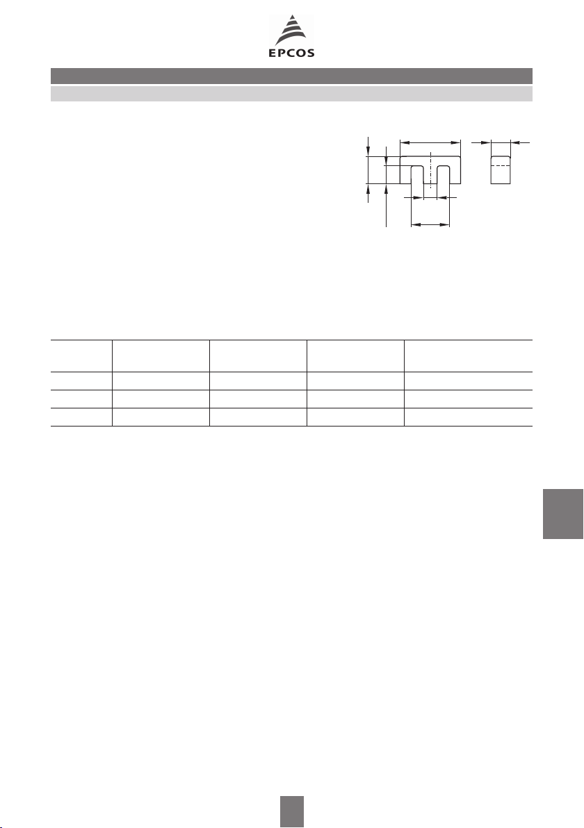
E6,3
B66300Core
■ For miniature transformers, e.g. DC/DC
_
6,3 2
0,25
converters for surface mounting
■ Available with SMD coil former
■ E cores are supplied as single units
Magnetic characteristics (per set)
Σl/A = 3,7 mm
–1
le= 12,2 mm
= 3,3 mm
A
e
A
= 2,6 mm
min
Ve= 40,3 mm
2
2
3
0,1
_
2,9
1,85+0,15
_
1,4
0,1
3,6+0,2
Approx. weight 0,12 g/set
Material A
nH
value
L
µ
e
A
L1min
Ordering code
mH
N30 700 + 40/– 30 % 2059 — B66300-G-X130
T38 1700 + 40/– 30 % 4990 — B66300-G-X138
N87 380 + 30/– 20 % 1120 300 B66300-G-X187
The A
value in the table applies to a core set comprising two ungapped cores.
L
_
0,1
FEK0361-H
385 08/01
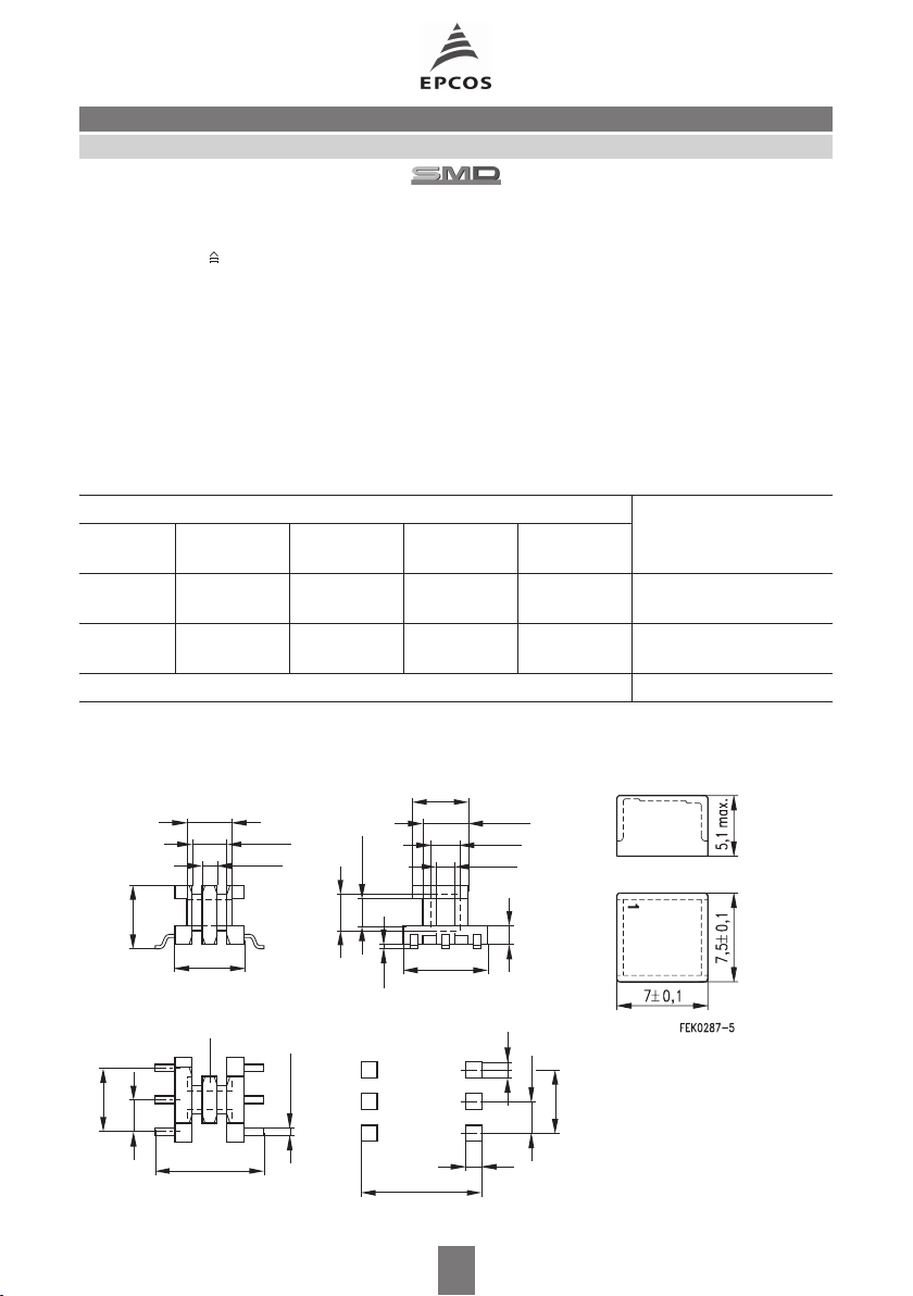
E6,3
B66301Accessories
SMD coil former with gullwing terminals
Material: GFR liquid crystal polymer (UL 94 V-0, insulation class to IEC 60085:
F max. operating temperature 155 °C), color code black
Solderability: to IEC 60068-2-20, test Ta, method 1 (aging 3): 350 °C, 1 s
Resistance to soldering heat: to IEC 60068-2-20, test Tb, method 1B: 350 °C, 3,5 s
permissible soldering temperature for wire-wrap connection on coil former: 400 °C, 1 s
Winding: see “Processing Notes”, page 160
Plastic cover cap
Used to protect the transformer against external influences, for stamping and for improved processing on assembly machines
Material: see coil former, color code white
Coil former Ordering code
Sections A
mm
N
2
l
N
mm
A
µΩ
value
R
Terminals
1 1,62 12,8 272 4 B66301-B1004-T1
6 B66301-B1006-T1
2 0,9 12,8 490 4 B66301-B1004-T2
6 B66301-B1006-T2
Plastic cover cap B66301-C2000
Coil former Plastic cover cap
_
3,5 0,1
2,7±0,1
1,2±0,1
4,9 max.
5,5±0,1
Omitted in
1-section version
1
2
3
2,54
2 x 2,54 = 5,08
Terminals 2 and 5 are
omitted in 4-terminal version
6
5
4
8,5±0,1
3±0,1
0,6±0,05
4,4±0,1
2,1+0,1
9,5
6,3
_
0,10,2
_
Recommended
PCB layout
0,2
3,5±0,1
_
2,4
0,1
1,5+0,1
1,2
1,2
FEK0421-U
1,5±0,1
2,54
5,08
386 08/01
 Loading...