

Page 1

Ferrites and accessories
RM 14, RM 14 LP
Cores and accessories
Series/Type: B65887, B65888
Date: May 2017
EPCOS AG 2017. Reproduction, publication and dissemination of this publication, enclosures hereto and the
information contained therein without EPCOS’ prior express consent is prohibited.
EPCOS AG is a TDK Group Company.
Page 2
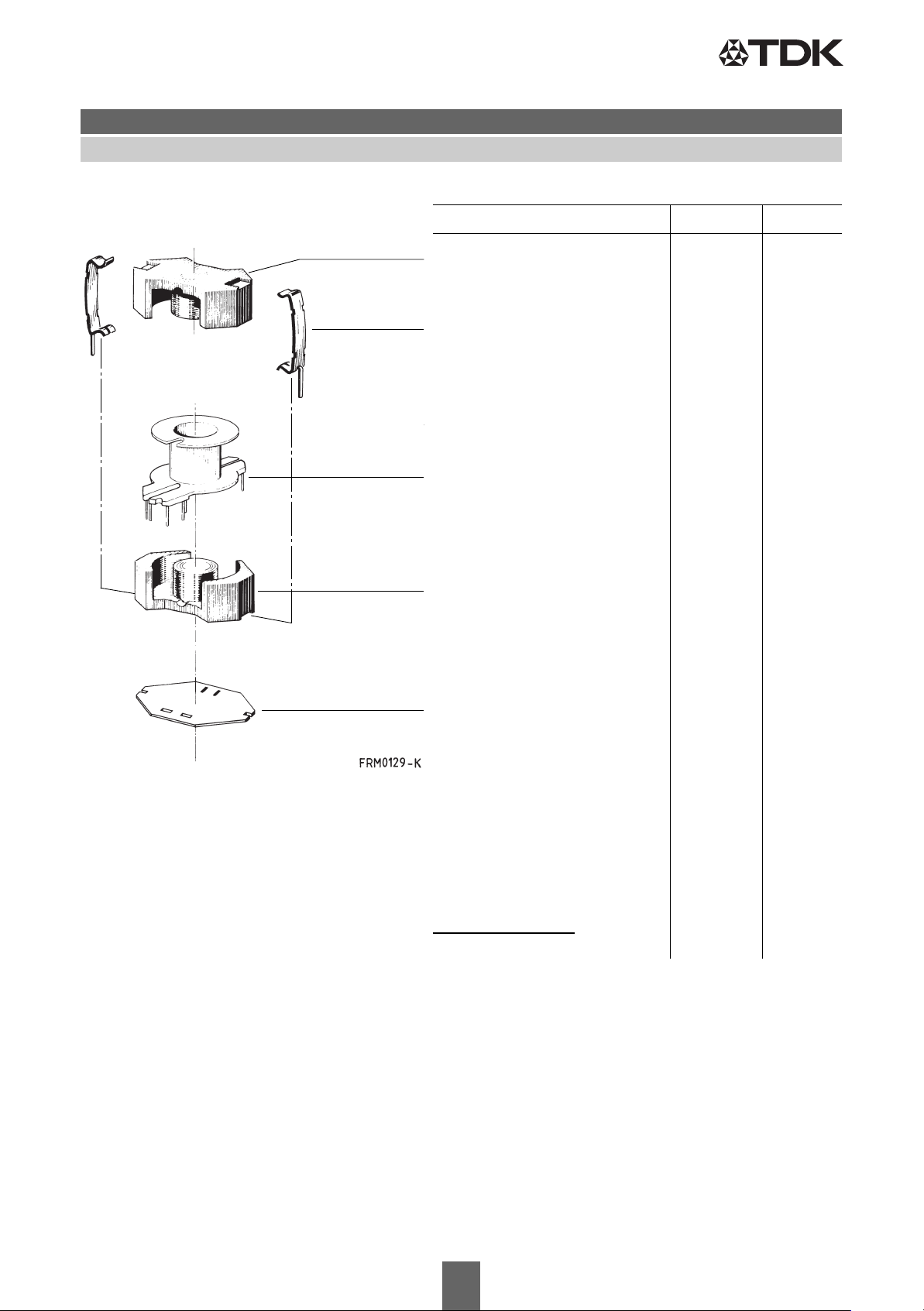
RM 14
Core and accessories
Individual parts
Part no. Page
Core B65887 3
Clamps B65888 6
Coil former B65888 4
Core B65887 3
Insulating washer B65888 6
Example of an assembly set
Also available: Coil former for
power applications B65888 5
RM 14 low-profile:
Core B65887P 7
Please read Cautions and warnings and
Important notes at the end of this document.
2 5/17
Page 3
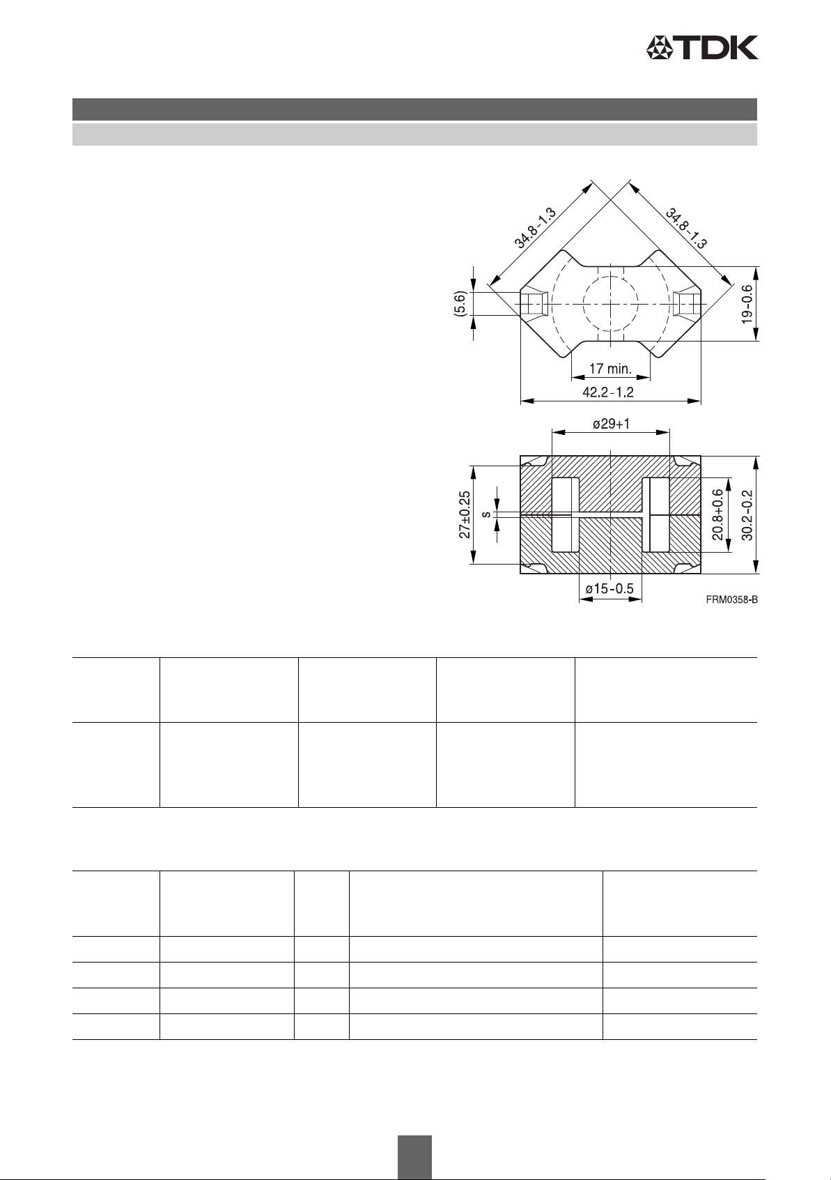
RM 14
■ To IEC 62317-4
■ Optimized core cross section and increased
thickness of base for power applications
■ Without center hole
■ Delivery mode: sets
Magnetic characteristics (per set)
Σl/A= 0.35 mm
l
= 70 mm
e
= 200 mm
A
e
A
= 170 mm
min
Ve= 14000 mm
Approx. weight 74 g/set
–1
2
2
3
B65887Core
Gapped (A
Material A
values/air gaps examples)
L
value
L
s
μ
e
Ordering code
approx.
nH
mm
-E without center hole
N41 160 ±3% 1.90 45 B65887E0160A041
250 ±3% 1.00 70 B65887E0250A041
400 ±3% 0.50 111 B65887E0400A041
1000 ±5% 0.15 279 B65887E1000J041
Ungapped
Material A
value
L
μ
e
P
V
Ordering code
-E without center
nH
W/set
hole
N49 3900 +30/–20% 1090 < 2.37 ( 50 mT, 500 kHz, 100 °C) B65887E0000R049
N87 6000 +30/–20% 1670 < 7.40 (200 mT, 100 kHz, 100 °C) B65887E0000R087
N97 6000 +30/–20% 1670 < 5.60 (200 mT, 100 kHz, 100 °C) B65887E0000R097
N41 6800 +30/–20% 1890 < 2.52 (200 mT, 25 kHz, 100 °C) B65887E0000R041
Other A
Please read Cautions and warnings and
Important notes at the end of this document.
values/air gaps and materials available on request ─ see Processing remarks on page 8.
L
3 5/17
Page 4
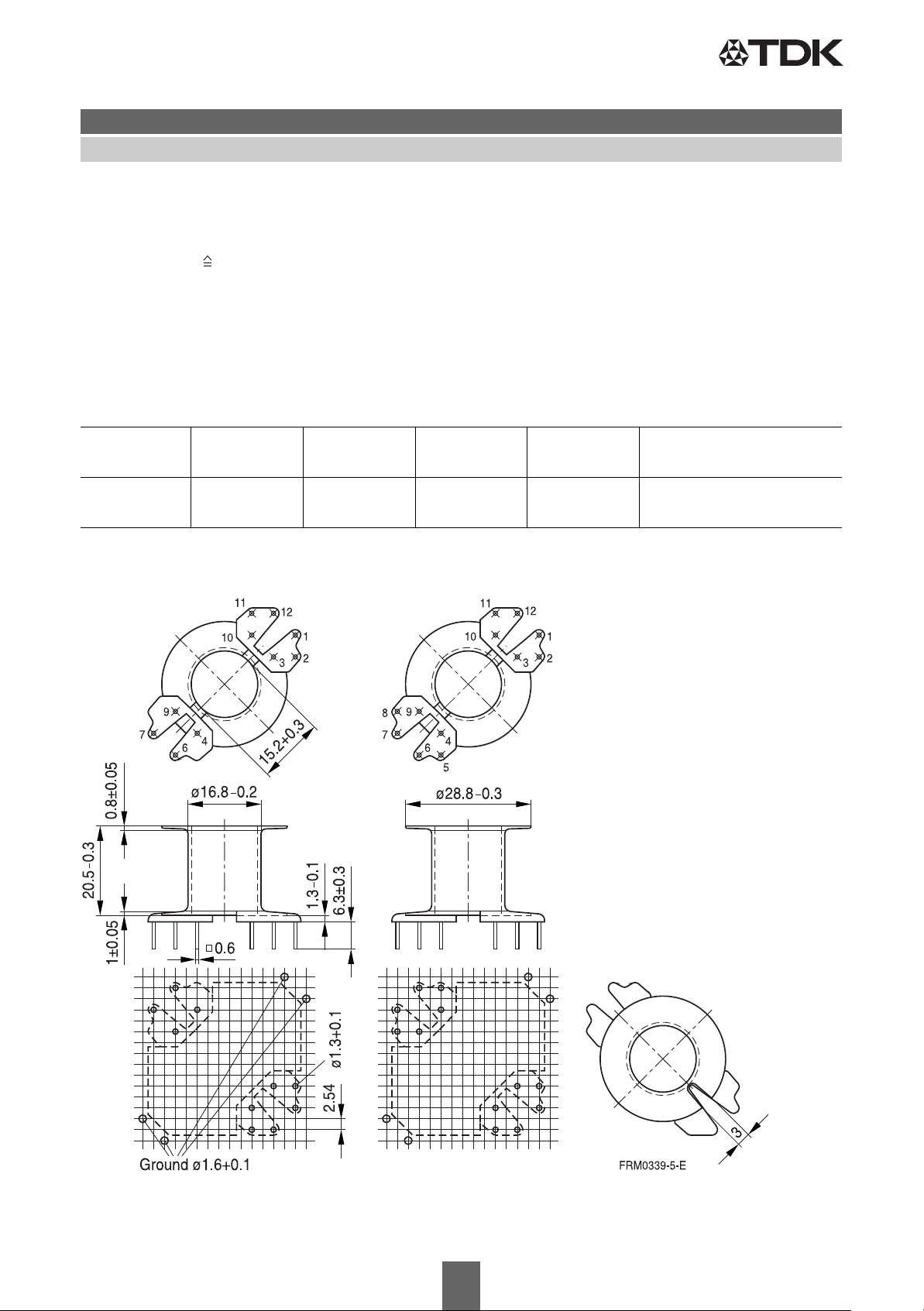
Hole arrangement
View in mounting direction
RM 14
Coil former
Material: GFR thermosetting plastic (UL 94 V-0, insulation class to IEC 60085:
F max. operating temperature 180 °C), color code black
®
Sumikon PM 9630
Solderability: to IEC 60068-2-20, test Ta, method 1 (aging 3): 235 °C, 2 s
Resistance to soldering heat: to IEC 60068-2-20, test Tb, method 1B: 350 °C, 3.5 s
Winding: see Processing notes, 2.1
Pins: Squared pins
For matching clamp and insulating washer see page 6.
[E41429 (M)], SUMITOMO BAKELITE CO LTD
B65888Accessories
Sections A
N
mm
l
2
N
mm
A
R
μΩ
value
Pins Ordering code
1 107 71.5 23 10 B65888N1010D001
12 B65888N1012D001
10 pins 12 pins
Please read Cautions and warnings and
Important notes at the end of this document.
4 5/17
Page 5
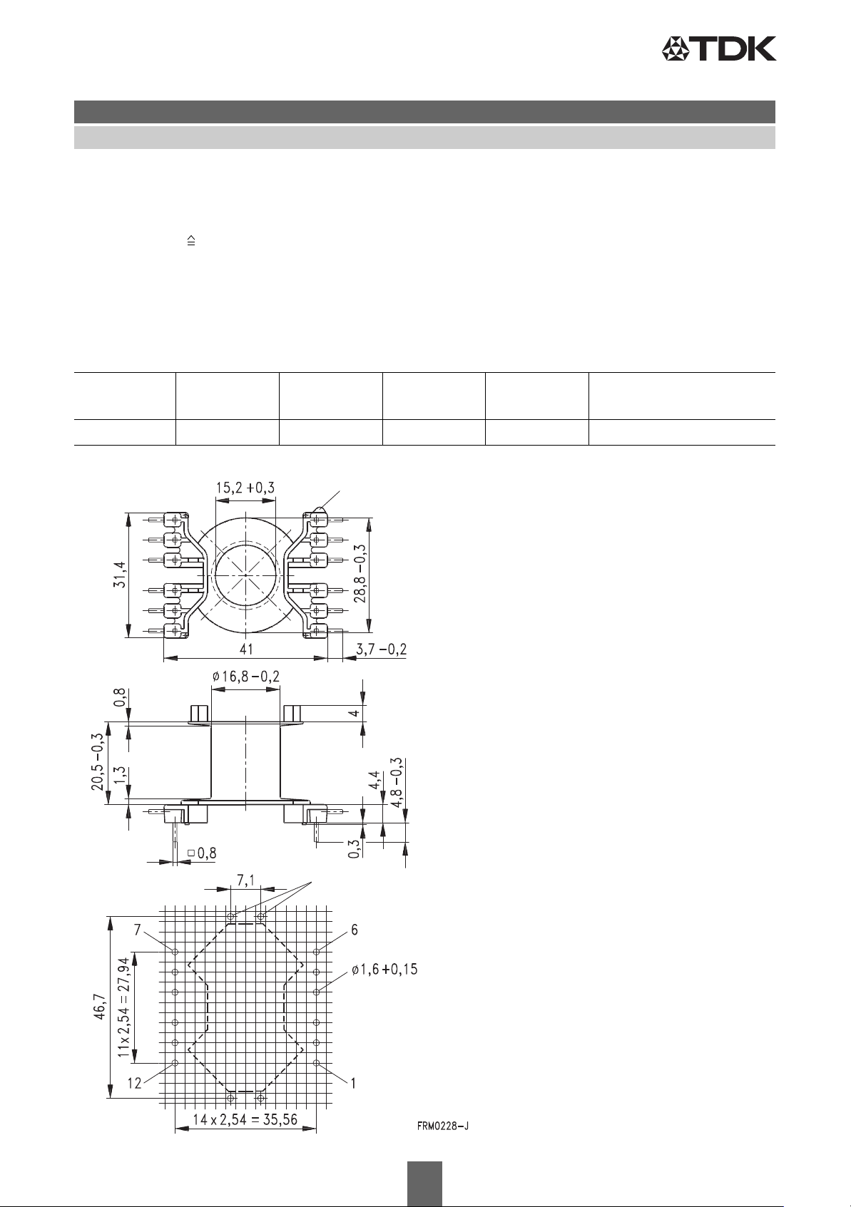
Hole arrangement
View in mounting direction
(Note half pitch!)
Marking of pin 1
Ground Ø 1.6+0.1
RM 14
Coil former for power applications
Material: GFR polyterephthalate (UL 94 V-0, insulation class to IEC 60085:
F max. operating temperature 155 °C), color code black
Valox 420-SE0 [E45329 (M)] SABIC INNOVATIVE PLASTICS B V
Solderability: to IEC 60068-2-20, test Ta, method 1 (aging 3): 235 °C, 2 s
Resistance to soldering heat: to IEC 60068-2-20, test Tb, method 1B: 350 °C, 3.5 s
Winding: see Processing notes, 2.1
For matching clamp and insulating washer see page 6.
B65888Accessories
Sections A
N
mm
l
2
N
mm
A
R
μΩ
value
Pins Ordering code
1 106 71.5 23 12 B65888C1512T001
Please read Cautions and warnings and
Important notes at the end of this document.
5 5/17
Page 6
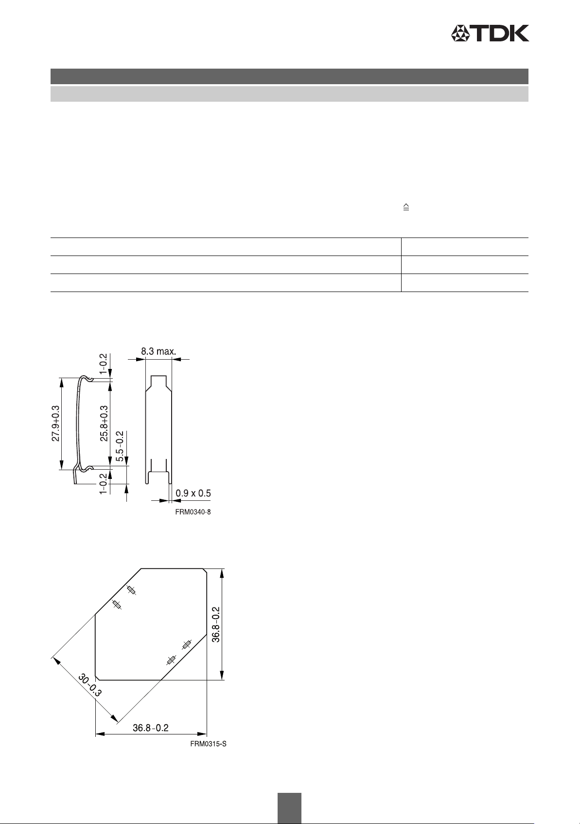
Insulating washer
RM 14
B65888Accessories
Clamp
■ With ground terminal, made of spring steel (tinned), 0.5 mm thick
■ Solderability to IEC 60068-2-20, test Ta, method 1 (aging 3): 235 °C, 2 s
Insulating washer for double-clad PCBs
■ Made of polyarylate film (UL 94 V-0, insulation class to IEC 60085: E 120 °C), 0.25 mm thick
Makrofol FR7-2 [E168120 (M)], COVESTRO AG
Ordering code
Clamp (ordering code per piece, 2 are required) B65888A2002X000
Insulating washer (bulk) B65888B2005X000
Clamp
Please read Cautions and warnings and
Important notes at the end of this document.
6 5/17
Page 7
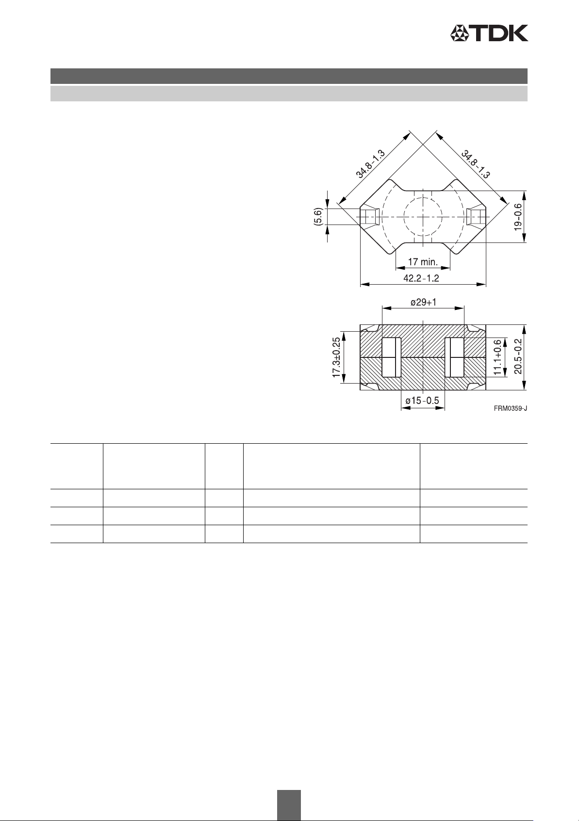
RM 14 »Low Profile«
■ To IEC 62317-4
■ For compact transformers
■ Without center hole
■ Delivery mode: sets
Magnetic characteristics (per set)
Σl/A= 0.25 mm
l
= 50.9 mm
e
= 201 mm
A
e
A
= 170 mm
min
Ve= 10230 mm
Approx. weight 55 g/set
–1
2
2
3
B65887PCore
Ungapped
Material A
L
nH
value
μ
e
P
V
Ordering code
W/set
N49 5100 +30/–20% 1030 < 2.0 ( 50 mT, 500 kHz, 100 °C) B65887P0000R049
N92 5400 +30/–20% 1090 < 6.1 (200 mT, 100 kHz, 100 °C) B65887P0000R092
N87 7100 +30/–20% 1430 < 5.5 (200 mT, 100 kHz, 100 °C) B65887P0000R087
Other A
values/air gaps and materials available on request ─ see Processing remarks on page 8.
L
Please read Cautions and warnings and
Important notes at the end of this document.
7 5/17
Page 8

Ferrites and accessories
Cautions and warnings
Cautions and warnings
Mechanical stress and mounting
Ferrite cores have to meet mechanical requirements during assembling and for a growing number
of applications. Since ferrites are ceramic materials one has to be aware of the special behavior
under mechanical load.
As valid for any ceramic material, ferrite cores are brittle and sensitive to any shock, fast temperature changing or tensile load. Especially high cooling rates under ultrasonic cleaning and high static
or cyclic loads can cause cracks or failure of the ferrite cores.
For detailed information see data book, chapter “General - Definitions, 8.1”.
Effects of core combination on A
value
L
Stresses in the core affect not only the mechanical but also the magnetic properties. It is apparent
that the initial permeability is dependent on the stress state of the core. The higher the stresses are
in the core, the lower is the value for the initial permeability. Thus the embedding medium should
have the greatest possible elasticity.
For detailed information see data book, chapter “General - Definitions, 8.1”.
Heating up
Ferrites can run hot during operation at higher flux densities and higher frequencies.
NiZn-materials
The magnetic properties of NiZn-materials can change irreversible in high magnetic fields.
Ferrite Accessories
EPCOS ferrite accessories have been designed and evaluated only in combination with EPCOS
ferrite cores. EPCOS explicitly points out that EPCOS ferrite accessories or EPCOS ferrite cores
may not be compatible with those of other manufacturers. Any such combination requires prior testing by the customer and will be at the customer‘s own risk.
EPCOS assumes no warranty or reliability for the combination of EPCOS ferrite accessories with
cores and other accessories from any other manufacturer.
Processing remarks
The start of the winding process should be soft. Else the flanges may be destroyed.
– Too strong winding forces may blast the flanges or squeeze the tube that the cores can not be
mounted any more.
– Too long soldering time at high temperature (>300 °C) may effect coplanarity or pin arrange-
ment.
– Not following the processing notes for soldering of the J-leg terminals may cause solderability
problems at the transformer because of pollution with Sn oxyde of the tin bath or burned insulation of the wire. For detailed information see chapter “Processing notes”, section 2.2.
– The dimensions of the hole arrangement have fixed values and should be understood as
a recommendation for drilling the printed circuit board. For dimensioning the pins, the group
of holes can only be seen under certain conditions, as they fit into the given hole arrangement.
To avoid problems when mounting the transformer, the manufacturing tolerances for positioning
the customers’ drilling process must be considered by increasing the hole diameter.
Please read Cautions and warnings and
Important notes at the end of this document.
8 5/17
Page 9

Ferrites and accessories
Cautions and warnings
Display of ordering codes for EPCOS products
The ordering code for one and the same product can be represented differently in data sheets,
data books, other publications and the website of EPCOS, or in order-related documents such as
shipping notes, order confirmations and product labels. The varying representations of the
ordering codes are due to different processes employed and do not affect the
specifications of the respective products. Detailed information can be found on the Internet
under www.epcos.com/orderingcodes.
Please read Cautions and warnings and
Important notes at the end of this document.
9 5/17
Page 10
Ferrites and accessories
Symbols and terms
Symbols and terms
Symbol Meaning Unit
A
A
e
A
L
A
L1
A
min
A
N
A
R
B
ΔB
ˆ
B
ˆ
ΔB
B
DC
B
R
B
S
C
0
CDF
DF
d
E
a
f
f
cutoff
f
max
f
min
f
r
f
Cu
g
H
ˆ
H
H
DC
H
c
h
h/μ
I
I
DC
ˆ
I
J
k
k
3
k
3c
L
Cross section of coil
Effective magnetic cross section
Inductance factor; A
= L/N
L
2
Minimum inductance at defined high saturation ( μa)
Minimum core cross section
Winding cross section
Resistance factor; A
= RCu/N
R
2
RMS value of magnetic flux density
Flux density deviation
Peak value of magnetic flux density
Peak value of flux density deviation
DC magnetic flux density
Remanent flux density
Saturation magnetization
Winding capacitance
Core distortion factor
Relative disaccommodation coefficient DF = d/μ
i
Disaccommodation coefficient
Activation energy
Frequency
Cut-off frequency
Upper frequency limit
Lower frequency limit
Resonance frequency
Copper filling factor
Air gap
RMS value of magnetic field strength
Peak value of magnetic field strength
DC field strength
Coercive field strength
Hysteresis coefficient of material
2
i
Relative hysteresis coefficient
RMS value of current
Direct current
Peak value of current
Polarization
Boltzmann constant
Third harmonic distortion
Circuit third harmonic distortion
Inductance
mm
mm
nH
nH
mm
mm
μΩ = 10–6 Ω
Vs/m
Vs/m
Vs/m
Vs/m
Vs/m
Vs/m
Vs/m
F = As/V
mm
J
–1
s
–1
s
–1
s
–1
s
–1
s
mm
A/m
A/m
A/m
A/m
10
10
A
A
A
Vs/m
J/K
H = Vs/A
2
2
2
2
–4.5
, Hz
, Hz
, Hz
, Hz
, Hz
–6
cm/A
–6
cm/A
2
, mT
2
, mT
2
, mT
2
, mT
2
, mT
2
, mT
2
, mT
2
Please read Cautions and warnings and
Important notes at the end of this document.
10 5/17
Page 11
Ferrites and accessories
Symbols and terms
Symbol Meaning Unit
ΔL/L
L
0
L
H
L
p
L
rev
L
s
l
e
l
N
N
P
Cu
P
trans
P
V
PF
Q
R
R
Cu
R
h
ΔR
h
R
i
R
p
R
s
R
th
R
V
s
T
ΔT
T
C
t
t
v
tan δ
tan δ
L
tan δ
r
tan δ
e
tan δ
h
tan δ/μ
U
Û
V
e
Z
Z
n
Relative inductance change
Inductance of coil without core
Main inductance
Parallel inductance
Reversible inductance
Series inductance
Effective magnetic path length
Average length of turn
H
H
H
H
H
H
mm
mm
Number of turns
Copper (winding) losses
Transferrable power
Relative core losses
W
W
mW/g
Performance factor
Quality factor (Q = ωL/R
Resistance
Copper (winding) resistance (f = 0)
Hysteresis loss resistance of a core
R
change
h
Internal resistance
Parallel loss resistance of a core
Series loss resistance of a core
Thermal resistance
Effective loss resistance of a core
Total air gap
Temperature
Temperature difference
Curie temperature
Time
= 1/tan δL)
s
Ω
Ω
Ω
Ω
Ω
Ω
Ω
K/W
Ω
mm
°C
K
°C
s
Pulse duty factor
Loss factor
Loss factor of coil
(Residual) loss factor at H → 0
Relative loss factor
Hysteresis loss factor
i
Relative loss factor of material at H → 0
RMS value of voltage
Peak value of voltage
Effective magnetic volume
Complex impedance
Normalized impedance |Z|
= |Z| /N2 × ε (le/Ae)
n
V
V
3
mm
Ω
Ω/mm
Please read Cautions and warnings and
Important notes at the end of this document.
11 5/17
Page 12
Ferrites and accessories
Symbols and terms
Symbol Meaning Unit
α
α
F
α
e
ε
r
Φ
η
η
B
η
i
λ
s
μ
μ
0
μ
a
μ
app
μ
e
μ
i
μp'
μ
"
p
μ
r
μ
rev
μs'
μ
"
s
μ
tot
ρ
Σl/A
τ
Cu
ω
Temperature coefficient (TK)
Relative temperature coefficient of material
Temperature coefficient of effective permeability
Relative permittivity
Magnetic flux
Efficiency of a transformer
Hysteresis material constant
Hysteresis core constant
Magnetostriction at saturation magnetization
Relative complex permeability
Magnetic field constant
Relative amplitude permeability
Relative apparent permeability
Relative effective permeability
Relative initial permeability
Relative real (inductive) component of μ
Relative imaginary (loss) component of μ
(for parallel components)
(for parallel components)
Relative permeability
Relative reversible permeability
Relative real (inductive) component of μ
Relative imaginary (loss) component of μ
(for series components)
(for series components)
Relative total permeability
derived from the static magnetization curve
Resistivity
Magnetic form factor
DC time constant τ
= L/RCu = AL/A
Cu
R
Angular frequency; ω = 2 Πf
1/K
1/K
1/K
Vs
-1
mT
A–1H
Vs/Am
–1
Ωm
–1
mm
s
–1
s
–1/2
All dimensions are given in mm.
Surface-mount device
Please read Cautions and warnings and
Important notes at the end of this document.
12 5/17
Page 13

Important notes
The following applies to all products named in this publication:
1. Some parts of this publication contain statements about the suitability of our products for
certain areas of application. These statements are based on our knowledge of typical requirements that are often placed on our products in the areas of application concerned. We nevertheless expressly point out that such statements cannot be regarded as binding statements
about the suitability of our products for a particular customer application. As a rule, EPCOS is either unfamiliar with individual customer applications or less familiar with them than the
customers themselves. For these reasons, it is always ultimately incumbent on the customer to
check and decide whether an EPCOS product with the properties described in the product specification is suitable for use in a particular customer application.
2. We also point out that in individual cases, a malfunction of electronic components or fail-
ure before the end of their usual service life cannot be completely ruled out in the current
state of the art, even if they are operated as specified. In customer applications requiring a
very high level of operational safety and especially in customer applications in which the malfunction or failure of an electronic component could endanger human life or health (e.g. in accident prevention or life-saving systems), it must therefore be ensured by means of suitable design of the customer application or other action taken by the customer (e.g. installation of protective circuitry or redundancy) that no injury or damage is sustained by third parties in the event
of malfunction or failure of an electronic component.
3. The warnings, cautions and product-specific notes must be observed.
4. In order to satisfy certain technical requirements, some of the products described in this pub-
lication may contain substances subject to restrictions in certain jurisdictions (e.g. because they are classed as hazardous). Useful information on this will be found in our Material
Data Sheets on the Internet (www.epcos.com/material). Should you have any more detailed
questions, please contact our sales offices.
5. We constantly strive to improve our products. Consequently, the products described in this
publication may change from time to time. The same is true of the corresponding product
specifications. Please check therefore to what extent product descriptions and specifications
contained in this publication are still applicable before or when you place an order.
We also reserve the right to discontinue production and delivery of products. Consequent-
ly, we cannot guarantee that all products named in this publication will always be available. The
aforementioned does not apply in the case of individual agreements deviating from the foregoing
for customer-specific products.
6. Unless otherwise agreed in individual contracts, all orders are subject to the current version
of the “General Terms of Delivery for Products and Services in the Electrical Industry”
published by the German Electrical and Electronics Industry Association (ZVEI).
7. The trade names EPCOS, CeraCharge, CeraDiode, CeraLink, CeraPad, CeraPlas, CSMP,
CTVS, DeltaCap, DigiSiMic, ExoCore, FilterCap, FormFit, LeaXield, MiniBlue, MiniCell, MKD,
MKK, MotorCap, PCC, PhaseCap, PhaseCube, PhaseMod, PhiCap, PowerHap, PQSine,
PQvar, SIFERRIT, SIFI, SIKOREL, SilverCap, SIMDAD, SiMic, SIMID, SineFormer, SIOV,
ThermoFuse, WindCap are trademarks registered or pending in Europe and in other
countries. Further information will be found on the Internet at www.epcos.com/trademarks.
Please read Cautions and warnings and
Important notes at the end of this document.
13 5/17
 Loading...